Carrier i-Vu XT Installation manual

i-Vu® XT Router (drv_gen5) CARRIER CORPORATION ©2022
Installation and Start-up Guide i All rights reserved
i
i-
-V
Vu
u®
®
X
XT
T
R
Ro
ou
ut
te
er
r
(
(d
dr
rv
v_
_g
ge
en
n5
5)
)
I
In
ns
st
ta
al
ll
la
at
ti
io
on
n
a
an
nd
d
S
St
ta
ar
rt
t-
-u
up
p
G
Gu
ui
id
de
e
Carrier ©2022 · Catalog No. 11-808-826-01 · 1/11/2022

Verify that you have the most current version of this document from www.hvacpartners.com, the Carrier Partner
Community website, or your local Carrier office.
Important changes are listed in Document revision history at the end of this document.
Carrier ©2022. All rights reserved.

Contents
What is the i-Vu® XT Router? ..................................................................................................................................... 1
Specifications ........................................................................................................................................................2
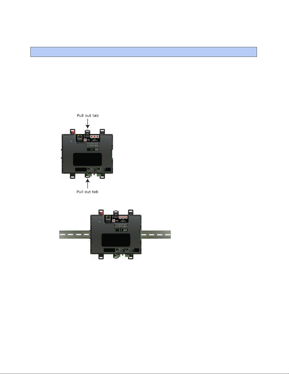
To mount the i-Vu® XT Router.................................................................................................................................... 5
Wiring for power .......................................................................................................................................................... 7
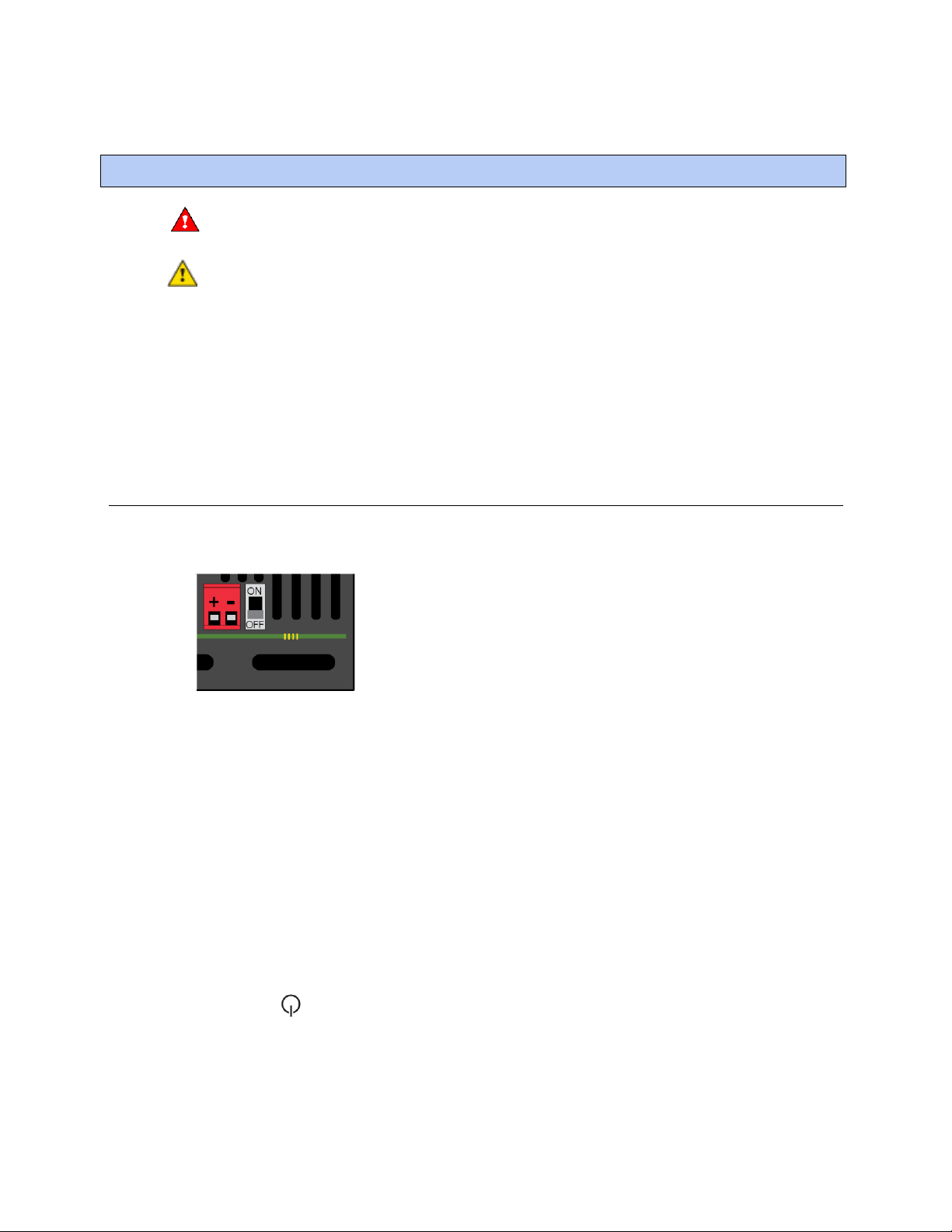
To wire for power ..................................................................................................................................................7
Connecting to the router through the Service Port ................................................................................................... 8
Connecting to the router through the Gig-E Port....................................................................................................... 9
Addressing the i-Vu® XT Router ...............................................................................................................................10
To set the IP address......................................................................................................................................... 11
To set an IPv6 address...................................................................................................................................... 13
To set the Port S1 address and baud rate ..................................................................................................... 15
To set the Port S2 address and baud rate ..................................................................................................... 15
Wiring for communications ......................................................................................................................................16
Wiring specifications ......................................................................................................................................... 16
To connect the i-Vu® XT Router to the Ethernet........................................................................................... 17
To wire to a BACnet/ARCNET network ........................................................................................................... 17
To wire to a BACnet MS/TP network .............................................................................................................. 18
Find and upload in the i-Vu® interface ....................................................................................................................19
Downloading the driver..................................................................................................................................... 19
Adjusting driver properties and controller setup through the Service Port or the i-Vu® interface .....................20
Connections tabs ............................................................................................................................................... 20
Device tab............................................................................................................................................20
Gig-E Port using BACnet/IPv4.............................................................................................................22
Gig-E Port using BACnet/IPv6 or BACnet/Ethernet ...........................................................................24
BACnet/SC Port tab.............................................................................................................................25
Port S1 and Port S2 ............................................................................................................................27
Advanced tabs.................................................................................................................................................... 29
Security tab..........................................................................................................................................29
Alarms tab............................................................................................................................................30
Notification Class tab ..........................................................................................................................31
Controller Clock tab.............................................................................................................................33
Color Cache tab ...................................................................................................................................34
Diagnostics tab....................................................................................................................................34
Network tab .........................................................................................................................................35
Troubleshooting .........................................................................................................................................................36
LEDs ..................................................................................................................................................................... 36
To get a Module Status report ......................................................................................................................... 38
To get a Device Log ........................................................................................................................................... 39
To get the i-Vu® XT Router's serial number .................................................................................................. 39
To replace the i-Vu® XT Router's fuse ............................................................................................................ 39
To take the i-Vu® XT Router out of service.................................................................................................... 41
To troubleshoot BACnet/SC connection issues ............................................................................................ 41
Compliance ................................................................................................................................................................42
FCC Compliance................................................................................................................................................. 42
CE Compliance ................................................................................................................................................... 42
Industry Canada Compliance........................................................................................................................... 42
BACnet Compliance........................................................................................................................................... 42
Appendix - Module Status field descriptions ...........................................................................................................43
Document revision history ........................................................................................................................................45

i-Vu® XT Router (drv_gen5) CARRIER CORPORATION ©2022
Installation and Start-up Guide 1 All rights reserved
The i-Vu® XT Router (part no. XT-RB) with drv_gen5 driver:
•Provides BACnet routing between any supported BACnet communication types
•Supports DHCP IP addressing
•Can serve as a BACnet Broadcast Management Device (BBMD)
•Supports Foreign Device Registration (FDR)
•Works with the i-Vu® v8.0 or later system
What is the i-Vu® XT Router?

i-Vu® XT Router (drv_gen5) CARRIER CORPORATION ©2022
Installation and Start-up Guide 2 All rights reserved
The i-Vu® XT Router has 4 physical BACnet communication ports:
Port
Port type
For routing this type
of communication...
At...
Gig-E
10/100/1000 Mbps Ethernet
BACnet/IP
BACnet/Ethernet
10, 100, or 1000 Mbps (1
Gbps)
S1
High-speed EIA-485 port
BACnet/ARCNET
BACnet/MSTP
156 kbps
9.6 to 115.2 kbps
S2
Electrically isolated EIA-485 port
BACnet/MSTP
9.6 to 115.2 Kbps
Service
Port
10/100 Mbps Ethernet
HTTP/IP
BACnet/IP Service Port
10 or 100 Mbps
i-Vu® XT Router also has a USB port for recovery.
Specifications
Driver
drv_gen5_< version >
NOTE For the fwex driver instructions, see the (part# i-Vu® XT Router) (drv_fwex)
Installation and Start-up Guide.
Power
24 Vac ±10%, 50–60 Hz, 50 VA
26 Vdc ±10%, 15 W
Gig-E port
10/100/1000 BaseT Ethernet port for BACnet/IP and/or BACnet/Ethernet
communication on the Ethernet at 10, 100, or 1000 Mbps, full duplex
Port S1
For communication with either of the following:
•A BACnet ARCNET network at 156 kbps
•A BACnet MS/TP network at 9600 to 115200 bps
This port's End of Net? switch can be set to Yes to terminate the network segment.
Port S2
For communication with a BACnet MS/TP network at 9600 to 115200 bps. This
port's End of Net? switch can be set to Yes to terminate the network segment.
Service Port
Ethernet port at 10 or 100 Mbps for system start-up and troubleshooting
USB port
USB 2.0 host port for device recovery
Microprocessor
32-bit ARM Cortex-A8, 600MHz, processor with multi-level cache memory
Memory
16 GBs eMMC Flash memory (120 MB available for use) and 256 MB DDR3
DRAM.
User data is archived to non-volatile Flash memory when parameters are changed,
every 90 seconds, and when the firmware is deliberately restarted.
Real-time clock
Real-time clock keeps track of time in the event of a power failure for up to 3 days.

i-Vu® XT Router (drv_gen5) CARRIER CORPORATION ©2022
Installation and Start-up Guide 3 All rights reserved
Protection
Device is protected by a replaceable, fast acting, 250 Vac, 2A, 5mm x 20mm glass
fuse.
The power and network ports comply with the EMC requirements EN50491-5-2.
CAUTION To protect against large electrical surges on serial EIA-485
networks, place a PROT485 at each place wire enters or exits the building.
LED status indicators
•Tricolor NET LED to show network status
•Tricolor SYS LED to show system status
•A TX (Transmit) and RX (Receive) LED for the following ports:
Gig-E
Port S1
Port S2
See LEDs (page 36).
Environmental operating
range
-40 to 158°F (-40 to 70°C), 10-95% relative humidity, non-condensing
Physical
Fire-retardant plastic ABS, UL94-5VA
Terminal blocks and
connectors
Screw-type terminal blocks.
0.2 in (5.08 mm) pitch connectors
Mounting
35mm DIN rail mounting or screw mounting
Overall dimensions
A:
B:
Depth:
7.1 in. (18.03 cm)
6.95 in. (17.65 cm)
2.09 in. (5.31 cm)
Screw mounting dimensions
C:
D:
6.45 in (16.38 cm)
4.1 in. (10.4 cm)
Weight
1 lb. 1 oz. (0.482 kg)
BACnet Support
Conforms to the BACnet Router (B-R-TR) Standard Device Profile as defined in
ANSI/ASHRAE Standard 135-2012 (BACnet) Annex L, Protocol Revision 14

i-Vu® XT Router (drv_gen5) CARRIER CORPORATION ©2022
Installation and Start-up Guide 4 All rights reserved
Compliance
United States of America:
FCC compliant to Title CFR47, Chapter 1, Subchapter A, Part 15, Subpart B, Class
A; UL Listed to UL 916, PAZX, Energy Management Equipment
Canada:
Industry Canada Compliant, ICES-003, Class A
cUL Listed UL 916, PAZX7, Energy Management Equipment
Europe: Mark
EN50491-5-2:2009; Part 5-2: EMC requirements for HBES/BACS used in
residential, commercial and light industry environment
RoHS Compliant: 2015/863/EU
REACH Compliant
Australia and New Zealand:
C-Tick Mark, AS/NZS 61000-6-3

i-Vu® XT Router (drv_gen5) CARRIER CORPORATION ©2022
Installation and Start-up Guide 5 All rights reserved
The i-Vu® XT Router must be mounted in a metal enclosure or cabinet which is properly rated for the location
where it is being installed.
NOTE We recommend screw mounting when installing in a high temperature and high humidity environment.
DIN rail mount
1 Push down and pull out the center tabs shown below to clear the din rail trough on the back of the router.
2 Place the router on the DIN rail so that the rail is in the trough on the back of the router.
3 Push the center tabs towards the router until you hear them click.
4 Pull gently on the router to verify that it is locked in place.
To mount the i-Vu® XT Router

i-Vu® XT Router (drv_gen5) CARRIER CORPORATION ©2022
Installation and Start-up Guide 6 All rights reserved
Screw Mount
Leave about 2 in. (5 cm) on each side of the router for wiring.
Insert #6 screws through the mounting holes. Use no more than 8 in.lbs. torque to secure plastic tab to mounting
surface.
A:
B:
C:
D:
Depth:
7.1 in. (18.03 cm)
6.95 in. (17.65 cm)
6.45 in. (16.38 cm)
4.1 in. (10.4 cm)
2.09 in (5.31 cm)

i-Vu® XT Router (drv_gen5) CARRIER CORPORATION ©2022
Installation and Start-up Guide 7 All rights reserved
WARNING Do not apply line voltage (mains voltage) to the router's ports and terminals.
CAUTIONS
•The i-Vu® XT Router is powered by a Class 2 power source. Take appropriate isolation measures when
mounting it in a control panel where non-Class 2 circuits are present.
•Carrier® controllers can share a power supply as long as you:
•Maintain the same polarity.
•Use the power supply only for Carrier® controllers.
To wire for power
1 Make sure the i-Vu® XT Router’s power switch is in the OFF position to prevent it from powering up before
you can verify the correct voltage.
2 Remove power from the power supply.
3 Pull the red screw terminal connector from the router's power terminals labeled 24 Vac/Vdc (+/-).
4 Connect the power supply's wires to the red screw terminal connector.
5 Connect an 18 AWG or larger wire from the power supply's negative (-) terminal to earth ground. This wire
must not exceed 12 in. (30.5 cm).
6 Apply power to the power supply.
7 Measure the voltage at the red screw terminal connector to verify that the voltage is within the operating
range of 20 to 30 Vac or 23.4 to 30 Vdc.
8 Insert the red screw terminal connector into the router's power terminals.
9 To verify the polarity of the wiring, measure the voltage from the negative terminal of the red screw terminal
connector to a nearby ground. The reading should be 0V.
10 Turn on the expander's power switch.
11 Verify that the LED on top of the router is on.
12 Measure the voltage at the red screw terminal connector to verify that the voltage is within the operating
range of 20 to 30 Vac or 23.4 to 30 Vdc.
Wiring for power

i-Vu® XT Router (drv_gen5) CARRIER CORPORATION ©2022
Installation and Start-up Guide 8 All rights reserved
Using a computer and an Ethernet cable, you can communicate with the i-Vu® XT Router through a web browser
to:
•View the router's Module Status report
•View/change router and network settings. Changes take effect immediately after clicking .
•Troubleshoot
You can set a site level Device Password to restrict access to the Service Port controller setup pages of a device
with a drv_gen5 driver. Set up the password in any of the following locations:
•In SiteBuilder, in the site dialog box
•In the i-Vu® interface, on the system level, on the Devices >Advanced tab
•If you have multiple sites, in the i-Vu® interface, at the site level > Properties page
1 Connect an Ethernet cable from a computer to the router as shown below.
2 Turn off the computer's Wi-Fi if it is on.
3 If your computer uses a static IP address, use the following settings:
○Address: 169.254.1.x, where x is 2 to 7
○Subnet Mask: 255.255.255.248
○Default Gateway: 169.254.1.1
4 If it uses a DHCP address, leave the address as it is.
5 Open a web browser on the computer.
6 Navigate to http://local.access or http://169.254.1.1 to see the Service Port controller setup pages.
NOTE The first time you access the router in the i-Vu® interface after you have changed settings through the
Service Port, be sure to upload the changes to the system database. This will preserve those settings when you
download memory or parameters to the router.
Connecting to the router through the Service Port

i-Vu® XT Router (drv_gen5) CARRIER CORPORATION ©2022
Installation and Start-up Guide 9 All rights reserved
Using a computer and an Ethernet cable, you can communicate with the i-Vu® XT Router through a web browser
to:
•View the router's Module Status report
•View/change router and network settings. Changes take effect immediately after clicking .
•Troubleshoot
To access the controller setup pages through the Gig-E network
1 In the i-Vu® interface, on the navigation tree, select the i-Vu® XT Router.
2 Right-click i-Vu® XT Router, select Driver Properties > Settings tab > Advanced > Security tab.
3 Enable Allow Configuration on Gig-E Port .
4 You can set a site level Device Password to restrict access to the Service Port controller setup pages of a
device with a drv_gen5 driver. Set up the password in any of the following locations:
○In SiteBuilder, in the site dialog box
○In the i-Vu® interface, on the system level, on the Devices >Advanced tab
○If you have multiple sites, in the i-Vu® interface, at the site level > Properties page
5 Connect an Ethernet cable from a computer to the Gig-E network that the i-Vu® XT Router is communicating
on.
NOTE Based on the building network configuration, this connection could be at a building switch or panel-
mounted switch.
6 Turn off the computer's Wi-Fi if it is on.
7 If your computer uses a static IP address, use settings appropriate for the building network.
8 If it uses a DHCP address, leave the address as it is.
9 Open a web browser on the computer.
10 Navigate to http://<router ip address>.
NOTE The IP address is preset in the router for interfacing with the Ethernet network.
NOTE The first time you access the router in the i-Vu® interface after you have changed settings through the
Service Port, be sure to upload the changes to the system database. This will preserve those settings when you
download memory or parameters to the router.
Connecting to the router through the Gig-E Port

i-Vu® XT Router (drv_gen5) CARRIER CORPORATION ©2022
Installation and Start-up Guide 10 All rights reserved
Set this port's address ...
In this location...
See...
IP
Service Port
To set the IP address
IPv6
Service Port
To set an IPv6 address (page 13)
Port S1
Service Port
To set the Port S1 address and baud rate (page
15)
Port S2
Service Port
To set the Port S2 address and baud rate (page
15)
To access the controller setup through the Service Port:
1 Connect an Ethernet cable from a computer to the router as shown below.
2 Turn off the computer's Wi-Fi if it is on.
3 If your computer uses a static IP address, use the following settings:
○Address: 169.254.1.x, where x is 2 to 7
○Subnet Mask: 255.255.255.248
○Default Gateway: 169.254.1.1
4 If it uses a DHCP address, leave the address as it is.
5 Open a web browser on the computer.
6 Navigate to http://local.access or http://169.254.1.1 to see the Service Port controller setup pages.
Addressing the i-Vu® XT Router

i-Vu® XT Router (drv_gen5) CARRIER CORPORATION ©2022
Installation and Start-up Guide 11 All rights reserved
To set the IP address
You must define the i-Vu® XT Router's IP addressing (IP address, subnet mask, and default gateway) in the
Service Port controller setup pages so that the router can communicate with the i-Vu Pro Server on the IP network.
Use one of the IP addressing schemes described below with the associated instructions that follow.
Use a...
If...
Default IP Address
that your system creates
The answer to all of the above questions is no.
Custom Static IP Address
from your network administrator
You do not use a DHCP server and the answer to any of the
following questions is yes. Will the i-Vu® system:
•Share a facility's existing IP data network?
•Have 254 or more devices with static IP addresses?
•Be connected to the Internet?
•Have at least one device located on the other side of an IP
router?
•Have any third-party IP devices?
DHCP IP Address
generated by a DHCP server
The IP network uses a DHCP server for IP addressing
NOTE Carefully plan your addressing scheme to avoid duplicating addresses. If third-party devices are integrated
into the system, make sure your addresses do not conflict with their addresses.
To set a DHCP IP address
1 On the Service Port controller setup, click , select Modstat from the drop-down list, find the router’s
Ethernet MAC address, and write it down.
2 On the Connections page, under the Gig-E Port tab > Primary BACnet/IP, select DHCP in the drop-down list
for Address Mode.
3 Click .
4 Write down the IP Address.
5 Give the DHCP network administrator the IP address and Ethernet MAC address and ask him to reserve that
IP address for the router so that it always receives the same IP address from the DHCP server.
To set a custom IP address
1 Obtain the IP address, subnet mask, and default gateway address for the router from the facility network
administrator.
2 On the Connections page, under the Gig-E Port tab > Primary BACnet/IP, select Custom Static in the drop-
down list for Address Mode.
3 Enter the IP Address, Subnet Mask, and Default Gateway addresses that the network administrator gave
you.
4 Click .

i-Vu® XT Router (drv_gen5) CARRIER CORPORATION ©2022
Installation and Start-up Guide 12 All rights reserved
To set a default IP address
Default IP addressing assigns the following to the router:
•IP address = 192.168.168.x
where x is the setting on the rotary switches in the range from 1 to 253
•Subnet Mask = 255.255.255.0
•Default Gateway = 192.168.168.254
1 Set the router's three rotary switches to a unique address on the network. Set the left rotary switch to the
hundreds digit, the middle switch to the tens digit, and the right switch to the ones digit.
EXAMPLE The switches below are set to 125.
2 On the Connections page, under the Gig-E Port tab > Primary BACnet/IP, select Default IP Address in the
drop-down list for Address Mode.
3 Click .
CAUTION
•If you set the Default IP address on the controller setup Connections page > Gig-E Port tab and then change
the rotary switches, you must do one of the following to correct the IP address in the router:
○Click .
•Cycle the router's power.
You will then need to correct the IP address in the i-Vu® application using Find Devices and Upload All
Content. See the i-Vu® Help for more information.
NOTE The default address is an intranet address. Data packets from this address are not routable to the Internet.

i-Vu® XT Router (drv_gen5) CARRIER CORPORATION ©2022
Installation and Start-up Guide 13 All rights reserved
To set an IPv6 address
You must define the i-Vu® XT Router's IPv6 addressing (IPv6 address, multicast address, and default gateway) in
the Service Port controller setup pages so that the router can communicate with the i-Vu Pro Server on the IP
network.
Use one of the IPv6 addressing schemes described below with the instructions that follow below.
Use a...
If...
Default IP Address
that your system creates
fd01::192:168:168:<rotary>
Custom Static
from your network administrator
Select Custom Static if you have a permanent IP addresses which
does not change and is usually obtained from the network
administrator.
DHCP
generated by a DHCP server
The IP network uses a DHCP server for IP addressing
Link-Local
This is an autogenerated private IP address used for local network
segment communications. Segment starts with FE80.
SLAAC
Used for Global Scope addressing and multicasting. This is defined
by the building network administrator. Segment starts with FCxx or
FDxx.
NOTE Carefully plan your addressing scheme to avoid duplicating addresses. If third-party devices are integrated
into the system, make sure your addresses do not conflict with their addresses.
To set a custom IP address
1 Obtain the IP address, subnet mask, and default gateway address for the router from the facility network
administrator.
2 On the Connections page, under the Gig-E Port tab > BACnet/IPv6, select Custom Static in the drop-down list
for Address Mode.
3 Enter the IP Address, Prefix Length, and Default Gateway addresses that the network administrator gave
you.
4 Click .

i-Vu® XT Router (drv_gen5) CARRIER CORPORATION ©2022
Installation and Start-up Guide 14 All rights reserved
To set a default IP address
Default IP addressing assigns the following to the router:
•IP address = fd01::192:168:168:x
where x is the setting on the rotary switches in the range from 1 to 253
•Prefix Length = 64
•Default Gateway = fd01::192:168:168:254
1 Set the router's three rotary switches to a unique address on the network. Set the left rotary switch to the
hundreds digit, the middle switch to the tens digit, and the right switch to the ones digit.
EXAMPLE The switches below are set to 125.
2 In the Service Port controller setup pages on the Connections page, under the Gig-E Port tab > BACnet/IPv6,
select Default IP Address in the drop-down list for Address Mode.
3 Click .
CAUTIONS
•If you configure your i-Vu® XT Router to use link-local addressing, then your IPv6 connection must also be
configured to use link-local addressing. The i-Vu® Server address must start with fe80 and the Multicast
Address must start with ff02.
•If you set the Default IP address on the controller setup Connections page > Gig-E Port tab and then change
the rotary switches, you must do one of the following to correct the IP address in the router:
•Go to the controller setup Connections page and click .
•Cycle the router's power.
You will then need to correct the IP address in SiteBuilder.
NOTE The default address is an intranet address. Data packets from this address are not routable to the Internet.

i-Vu® XT Router (drv_gen5) CARRIER CORPORATION ©2022
Installation and Start-up Guide 15 All rights reserved
To set the Port S1 address and baud rate
The address should be in one of the following ranges based on the port's use.
•For ARCNET, the range is 1 to 254.
•For MS/TP, the range is 0 to 127.
On the Connections > Port S1 tab, type the address in the MAC Address field.
NOTE ARCNET is not supported on Port S2.
For MS/TP, set up the port's baud rate
1 On the Connections >Port S1 tab, select the Baud Rate. The default is 76,800 bps.
2 Click .
To set the Port S2 address and baud rate
1 On the Connections > Port S2 tab, type the address in the MAC Address field. The address must be in the
range of 0 to 127.
2 Select the MSTP Baud Rate. The default is 76,800 bps.
NOTE Enter the same baud rate for all devices on the MS/TP network.
3 Click .

i-Vu® XT Router (drv_gen5) CARRIER CORPORATION ©2022
Installation and Start-up Guide 16 All rights reserved
The i-Vu® XT Router communicates on the following ports.
Port
Protocol
Port type(s)
Speed(s)
Gig-E
BACnet/IPv4
BACnet/IPv6
and/or BACnet/Ethernet
Ethernet
10, 100, or 1000 Mbps (1 Gbps)
Port S1 1
BACnet/ARCNET
RS485
156 kbps
Port S1 1
or
Port S2
BACnet/MSTP
RS485
9.6 to 115.2 Kbps 2
Service Port 3
HTTP/IP
Ethernet
10 Mbps
100 Mbps
USB Port
USB2.0
USB
1Set the Port S1 Configuration rotary switch to:
0if the port is not used
1for MS/TP
2for ARCNET
2Default for MS/TP is 76.8 kbps.
3See Connecting to the router through the Service Port (page 8).
Wiring specifications
For...
Use...
Maximum Length
Ethernet
Cat5e or higher Ethernet cable
328 feet (100 meters)
ARCNET
22 AWG, low-capacitance, twisted, stranded,
shielded copper wire *
2000 feet (610 meters)
MS/TP
22 AWG, low-capacitance, twisted, stranded,
shielded copper wire *
2000 feet (610 meters)
*See the Open Controller Network Wiring Guide.
WARNING Do not apply line voltage (mains voltage) to the router's ports and terminals.
Wiring for communications

i-Vu® XT Router (drv_gen5) CARRIER CORPORATION ©2022
Installation and Start-up Guide 17 All rights reserved
To connect the i-Vu® XT Router to the Ethernet
Connect an Ethernet cable to the Gig-E Ethernet port.
If your system has multiple routers that reside on different IP subnets, you must set up one router on each IP
subnet as a BACnet/IP Broadcast Management Device (BBMD).
Every subnet with a router must have a BBMD configured in order for broadcasts from routers on that subnet to
reach the rest of the routers on the network.
NOTES
•The i-Vu® Standard or Plus application - If the i-Vu® web server is on a separate subnet than the rest of the
routers, the internal router must be assigned a routable IP address and configured as a BBMD.
•The i-Vu® Pro application - If the i-Vu® Pro server is on a separate subnet than the rest of the routers, you
must register it as a foreign device to a router acting as a BBMD device.
Use the BBMD Configuration Tool to:
•Write/read the Broadcast Distribution Table (BDT) of each BBMD device
•Allow controllers on one subnet to communicate with controllers on other subnets
•Enable the i-Vu® application to see, upload, or configure controllers on different subnets
To wire to a BACnet/ARCNET network
1 Turn off the i-Vu® XT Router's power.
2 Check the communications wiring for shorts and grounds.
3 Connect the communications wiring to Port S1’s screw terminals labeled Net +, Net -, and Shield.
NOTE Use the same polarity throughout the network segment.
4 If the router has a Port S1 Configuration rotary switch, set it to 2.
5 If the i-Vu® XT Router is at either end of a network segment, set the port's End of Net switch to Yes.
NOTE The router’s End of Net switch applies network termination and bias. See the Open Controller Network
Wiring Guide.
6 Turn on the router's power.
7 To verify communication with the network, get a Module Status report in the i-Vu® interface for a router on
the ARCNET network.
NOTE This step requires that you have discovered and uploaded the router in the i-Vu® application.
Other manuals for i-Vu XT
1
This manual suits for next models
2
Table of contents
Other Carrier Recording Equipment manuals

Carrier
Carrier System Touch Assembly instructions

Carrier
Carrier KSAIF0101AAA User manual

Carrier
Carrier 30RBV User manual

Carrier
Carrier APOLLO CONTROL 50HJQ004-016 User manual

Carrier
Carrier KSAIF0401AAA User manual

Carrier
Carrier KSAIC0301230 User manual

Carrier
Carrier Fireye NXTSD507HD Owner's manual

Carrier
Carrier CSM Operating instructions

Carrier
Carrier DLS VRF User manual

Carrier
Carrier System Touch Assembly instructions