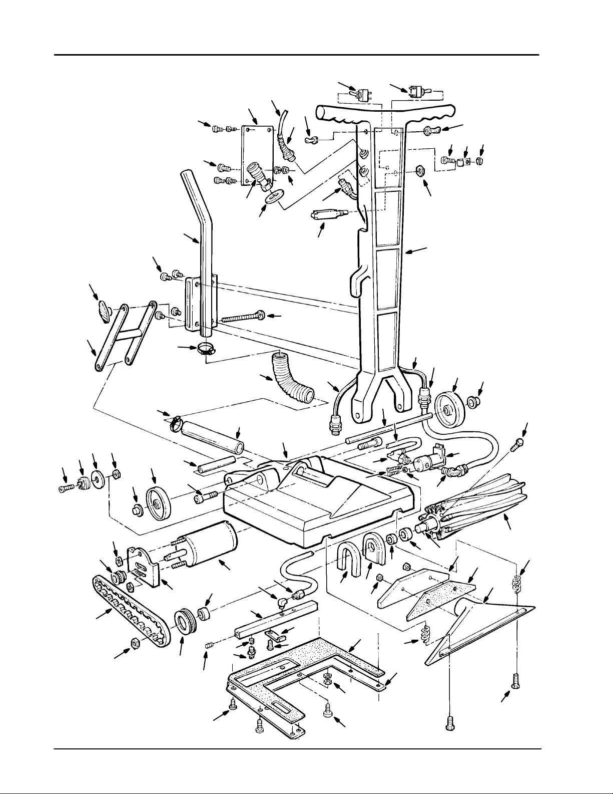
Castex PB-1600 Product manual

PB1600
608054
Rev. 00 (0799)
Brush Attachment For Carpet Extractors
MODEL:
607421
Operator and Parts Manual
A TENNANT COMPANY
1–800-522–7839
616-786–2330
FAX: 1–800–678–4240
CUSTOMER SERVICE: 1–800-365-6625
CASTEX INCORPORATED
12875 RANSOM STREET
HOLLAND MI 49424 U.S.A.
Home
Find...
Go To..

OPERATION
2PB-1600 (07–99)
This manual is furnished with each new model. It
provides necessary operation and machine
maintenance instructions and an illustrated parts list.
Read this manual completely and understand the
machine before operating or servicing it.
When ordering replacement parts, use the Parts Lists
in this manual. Before ordering parts or supplies, be
sure to have your machine model number and serial
number handy. Parts and supplies may be ordered by
phone or mail from any Authorized Service Center or
Distributor.
This machine will provide excellent service. However,
the best results will be obtained at minimum costs if:
The machine is operated with reasonable care.
The machine is maintained regularly - per the
machine maintenance instructions provided.
The machine is maintained with manufacturer
supplied or equivalent parts.
MACHINE DATA
Please fill out at time of installation for future reference.
Model No.- Install. Date - / /
Serial No.-
TABLE OF CONTENTS
SAFETY PRECAUTIONS 3. . . . . . . . . . . . . . . . . . . . . . .
MACHINE COMPONENTS 4. . . . . . . . . . . . . . . . . . . . . .
MACHINE SETUP 4. . . . . . . . . . . . . . . . . . . . . . . . . . . . .
MACHINE OPERATION 5. . . . . . . . . . . . . . . . . . . . . . . .
MACHINE MAINTENANCE 5. . . . . . . . . . . . . . . . . . . . .
TROUBLE SHOOTING 6. . . . . . . . . . . . . . . . . . . . . . . . .
SPECIFICATIONS 6. . . . . . . . . . . . . . . . . . . . . . . . . . . . .
ELECTRICAL DIAGRAM 7. . . . . . . . . . . . . . . . . . . . . . .
PARTS LIST 8. . . . . . . . . . . . . . . . . . . . . . . . . . . . . . . . . .
Home
Find...
Go To..

OPERATION
PB-1600 (07–99) 3
SAFETY PRECAUTIONS
This machine attachment is intended for commercial
use. It is suited for carpet extractors of 150psi solution
pressure or less. It is used to clean carpets in an
indoor environment and is not constructed for any
other use.
The following safety alert symbols are used throughout
this manual as indicated in their description.
WARNING: To warn of hazards or unsafe
practices which could result in severe personal
injury or death.
FOR SAFETY: To identify actions which must be
followed for safe operation of equipment.
The following information signals potentially dangerous
conditions to the operator or equipment:
FOR SAFETY:
1. Do not operate machine:
– Unless trained and authorized.
– Unless operator manual is read and
understood.
– In flammable or explosive areas unless
designed for use in those areas.
– Unless cord is properly grounded.
– With damaged cord or plug.
– If not in proper operating condition.
– In outdoor areas.
– In standing water.
2. Before operating machine:
– Make sure all safety devices are in place
and operate properly.
3. When using machine:
– Do not run machine over cord.
– Do not pull machine by plug or cord.
– Do not pull cord around sharp edges or
corners.
– Do not unplug by pulling on cord.
– Do not stretch cord.
– Do not handle plug with wet hands.
– Keep cord away from heated surfaces.
– Report machine damage or faulty
operation immediately.
4. Before leaving or servicing machine:
– Turn off machine.
– Unplug cord from wall outlet.
5. When servicing machine:
– Unplug cord from wall outlet.
– Avoid moving parts. Do not wear loose
jackets, shirts, or sleeves.
– Use manufacturer supplied or approved
replacement parts.
WARNING: Hazardous Voltage. Shock or
electrocution can result. Always unplug machine
before servicing.
WARNING: Flammable materials can cause
an explosion or fire. Do not use flammable
materials in tank(s).
WARNING: Flammable materials or reactive
metals can cause an explosion or fire. Do not pick
up.
GROUNDING INSTRUCTIONS
Machine must be grounded. If it should
malfunction or breakdown, grounding provides a
path of least resistance for electrical current to
reduce the risk of electrical shock. This machine
is equipped with a cord having an
equipment–grounding conductor and grounding
plug. The plug must be plugged into an
appropriate outlet that is properly installed in
accordance with all local codes and ordinances.
Do not remove ground pin; if missing, replace
plug before use.
GROUNDED OUT-
LET
(3 HOLE)
GROUNDING
PIN
Home
Find...
Go To..

OPERATION
4PB-1600 (07–99)
MACHINE COMPONENTS
2
41
3
5
7
6
8
1. Spray Switch
2. ON/OFF Switch
3. Circuit Breaker
4. Solution Hose Connection
5. Vacuum Hose Connection
6. Handle Adjustment Knob
7. Clear Intake Tube
8. Power Brush Head
MACHINE SETUP
1. Carefully check carton for signs of damage.
Report damages at once to carrier.
2. The machine is shipped fully assembled and is
ready for operation.
3. Prepare carpet extractor for use. See extractor’s
manual for setup instructions.
4. Connect vacuum and solution hoses to carpet
extractor and to brush attachment.
ATTENTION: This brush attachment is intended
for carpet extractors of 150 psi of solution
pressure or less. Damage due to the excess of 150
psi is not covered by the warranty.
5. Plug power cord to grounded wall outlet (shown
below) or for twist plug models plug cord directly
into a low pressure cannister extractor.
Grounded Outlet
Grounding
Edge/hole
Grouned
3 Hole Outlet
Ground Pin
(120V) (220V)
FOR SAFETY: Do not use machine unless cord is
properly grounded.
6. Loosen black knob at bottom of handle and lower
handle to a comfortable operating position. Tighten
knob to lock handle in place.
Home
Find...
Go To..

OPERATION
PB-1600 (07–99) 5
MACHINE OPERATION
FOR SAFETY: Do not operate machine unless
operator manual is read and understood.
1. Turn on the carpet extractor according to it’s
operating manual instructions.
2. Move the SPRAY switch to the upward position,
then squeeze the ON/OFF switch to start spray
and brush.
3. To begin cleaning: Pull the brush accessory
backwards slowing and slightly lift up on the
handle to apply brush pressure to the floor.
WARNING: Flammable materials or reactive
metals can cause an explosion or fire. Do not pick
up.
NOTE: If a spot does not come clean after first pass,
move the SPRAY switch to the downward position.
This stops the spray and allows you to scrub the spot
using only the brush.
4. When finished cleaning, turn off the extractor, then
squeeze the ON/OFF switch on the brush
accessory to relieve pressure in the solution hose.
5. Disconnect hoses and wrap the power cord
around the handle and cord wrap.
Brush Circuit Breaker
The machine is equipped with a brush circuit breaker.
Circuit Breaker will trip under conditions of excessive
brush overload. Periodically check brush for entangled
carpet strands and debris. If circuit breaker should trip.
Remove obstruction and reset circuit breaker switch
by pushing button located on side of handle. Resume
to normal operation.
MACHINE MAINTENANCE
FOR SAFETY: Before leaving or servicing
machine, turn off machine and unplug cord from
wall outlet.
Plumbing System
Each week of operation, flush out plumbing system
with an acetic acid solution. This will prevent the
plumbing system from clogging up with an alkaline
buildup. Follow instructions below:
Mix 473ml (2 cups) of acetic acid solution with 7.6L (2
gal) of host water, 60°C (140°F) max., in the
extractor’s solution tank. Hold a bucket under brush
attachment spray tips and spray solution for several
seconds. Allow solution to sit in machine for 12 hours.
Next, flush out machine with clean water before using
again.
Power Cord
Always wind power cord around handle and cord wrap
rather than loosely looped over handle. Should power
cord become worn, replace immediately.
Inspect cord strain relief regularly to ensure that it is
not pulling out of housing.
Brush and Belt
Inspect regularly for entangled carpet strands and
debris.
Pick–Up Head
Inspect pick up head intake for lodged debris. Use a
coat hanger to remove debris.
Vacuum Hose
Inspect Vacuum hose regularly for holes, loose cuffs
or clogged debris.
Home
Find...
Go To..

OPERATION
6PB-1600 (07–99)
TROUBLESHOOTING
PROBLEM CAUSE SOLUTION
No spray. SPRAY switch is positioned down-
ward. Position SPRAY switch upward.
ON/OFF switch not squeezed. Squeeze ON/OFF switch.
Clogged spray tips. Clean spray tips with an acetic acid
solution. See Machine Maintenance.
Clogged or faulty solenoid. Contact Service Center.
Extractor’s pump is faulty Contact Service Center.
Faulty wiring. Contact Service Center.
Brush does not spin. Brush clogged, which tripped brush
circuit breaker. Unplug power cord and remove
entangled carpet strands and debris
then reset circuit breaker.
ON/OFF switch not squeezed. Squeeze ON/OFF switch.
Brush or motor pulley loose. Tighten set screws on both pulleys.
Faulty brush motor. Contact Service Center.
Faulty wiring. Contact Service Center.
Building circuit breaker has tripped. Reset circuit breaker.
SPECIFICATIONS
MODEL NO. PB-1600
LENGTH 460 mm (18 in)
WIDTH 410 mm (16 in)
HEIGHT 1120 mm (44 in)
WEIGHT 17Kg (38 lbs)
BRUSH MOTOR 120V, .1 hp, 1A, 120W
BRUSH SPEED 1200 R.P.M.
POWER CORD LENGTH 7.5m (25 ft) Gauge–18–3
CLEANING PATH 406 mm (16 in)
MAXIMUM SOLUTION PRESSURE 10.3 BAR / 150 P.S.I.
Home
Find...
Go To..

ELECTRICAL DIAGRAM
7
PB-1600 (04–96)
REF LEGEND
BLK = Black
WHT = White
RED = Red
GRN = Green
S1 = Switch, ON/OFF
S2 = Switch, Spray
CB = Circuit Breaker
M1 = Motor, Brush
BR = Bridge Rectifier
SD = Solenoid
Home
Find...
Go To..

PARTS LIST
8PB-1600(09–96)
69
71
1
2
34
512
13 14
8
7
11
10
15
6
16 17
10
9
72
68
70
18 19 21 22
29
24
23
27
25
26
66
20
28
30
31
32
33
34
36
35
37 38
40
39
41
49
67
64
63
58
62 61 60 59
22
21
55
54
53
52 51
50
46
48
47
45
44
143
42
39
6
1
2
57
6
56
65
73
73
Home
Find...
Go To..

PARTS LIST
9
PB-1600 (07–99)
REF PART # DESCRIPTION QTY
1. 140890 SCREW, 10–24x1/2” 3
2. 140887 SCREW, 10–24 x 3/8 14
3. 230304.BK PLATE, COVER 1
4. 130212 CORD, 18/3 x 25 FT. 120V 1
130271 CORD, 25 FT. 220V 1
130504 PLUG, TWIST LOCK(NOT SHOWN) 1
5. 130137 GRIP, CORD 1
6. 140519 NUT, 10–24 5
7. 140034 WASHER, FLAT 1/2” 1
8. 150913 COUPLER, QUICK 1
9. 608037 HANDLE, BLUE 1
10. 578337000 BREAKER, CIRCUIT 1.5A 1
11. 150024 CONNECTOR, 1/4”X3/8” 1
12. 130990 BOOT, RUBBER 1
13. 130728 SWITCH, SPRAY 1
14. 130751 SWITCH, ON/OFF 1
15. 130753 BOOT, SWITCH 1
16. 140848 SCREW, 10–24x1/2” 1
17. 140324 CLAMP, 5/16” 1
18. 160473 TUBING, 3/8” X55” 4.5FT.
19. 130181 GRIP, CORD 2
20. 230609 AXLE, WHEEL 1
21. 103007 WHEEL 2
22. 103029 CAP, HUB 2
23. 150421 ELBOW, 90°1/4”X3/8” 1
24. 210033 VALVE, SOLENOID 120V 60 HZ 1
25. 140023 WASHER, INT. LOCK #8 2
26. 140801 SCREW, 8–32x3/8 2
27. 150414 ELBOW, ST. 90°1/4 1
28. 160468 TUBING, 1/4”x.916 1
29. 140554 SCREW, 1/4–20x3/4 4
30. 240004 BRUSH, CYLINDER 16” 1
31. 230257 SHAFT, BRUSH 16” 1
32. 100049 SEAL, BRUSH BEARING 2
33. 140125 BEARING, BRUSH 2
34. 230261 BLOCK, BEARING 2
35. 100005 GASKET, BEARING BLOCK 1
36. 140546 NUT, LOCK 5/16–18 2
37. 230610.BK WEIGHT, VACUUM HEAD 1
38. 100144 GASKET, WEIGHT 1
39. 140419 SPRING 2
40. 230608 TOOL, PICKUP HEAD 1
41. 140221 SCREW, 5/16–18x1–1/4” 2
42. 100734.BK PLATE, BRUSH 1
REF PART # DESCRIPTION QTY
43. 100006 GASKET, BASE PLATE 1
44. 230605 BRACKET, MANIFOLD 1
45. 201004 NOZZLE, #8003 4
46. 150208 PLUG, 1/8 3
47. 230267 MANIFOLD, 16” SPRAYBAR 1
48. 150407 ELBOW, ST. 90°1/8 1
49. 150022 ADAPTER, 1/4” 1
50. 230363 SPACER, BRUSH PULLY 1
51. 230505 PULLEY, BRUSH 1
52. 140548 NUT, JAM 5/16 1
53. 230507 BELT, BRUSH DRIVE 1
54. 230506 PULLEY, MOTOR 1
55. 140518 NUT, KEP 10–32–S/S 2
56. 230366 PLATE, MOTOR MOUNT 1
57. 130471 MOTOR, BRUSH 120 VOLT 1
190150 BRUSH CARD REPLMT 1
130472 MOTOR, BRUSH 220 VOLT 1
190154 BRUSH CARD REPLMT 1
58. 140564 BOLT, SHOULDER 3/8 x 3/4 2
59. 140539 NUT, KEPS 6/32 1
60. 140041 WASHER, FENDER 1
61. 130304 RECTIFIER 1
62. 140831 SCREW, 6–32X5/8 1
63. 140601 SPACER, AXLE 1
64. 240179 TUBE, CLEAR VACUUM 1
65. 101348 BASE, BLUE 1
66. 130668 ASM., CORD16/4X55” 1
67. 160615 HOSE, VACUUM 1–1/2X.5ft. 1
68. 240194 KNOB, PLASTIC T–BAR 1
69. 230607 LINK , ARM 1
70. 140209 BOLT, CARRIAGE 5/16–18X4–1/2 1
71. 230606.BK TUBE, VACUUM HOSE ATTCHMNT 1
72. 140885 SCREW, 1/4–20X1/2 4
73. 140307 CLAMP, HOSE 2
DECALS (NOT SHOWN)
120513 DECAL, OPERATING INST. 1
120619 DECAL, “WARNING..” 1
120846 DECAL, “LOW PRESURE..” 1
608055 DECAL, “PB-1600” 1
Home
Find...
Go To..
This manual suits for next models
1
Table of contents
Other Castex Lifting System manuals