Castex QJY2.5-H Instructions for use

0
Instructions and Maintenance
Original Manual
QJY2.5-H
Movable single post lift

1
Content
1Safety.................................................................................................................................2
1.1 Introduction..............................................................................................................2
1.2 Intended Use...........................................................................................................2
1.3 Safety Instructions for Commissioning.....................................................................2
1.4 Safety Instructions for Operation.............................................................................2
1.5 Safety Instructions for Servicing ..............................................................................3
1.6 Safety featuresl....................................................................................................................................3
1.7 Disposal of used oil .................................................................................................3
1.8 Machine demolition..................................................................................................3
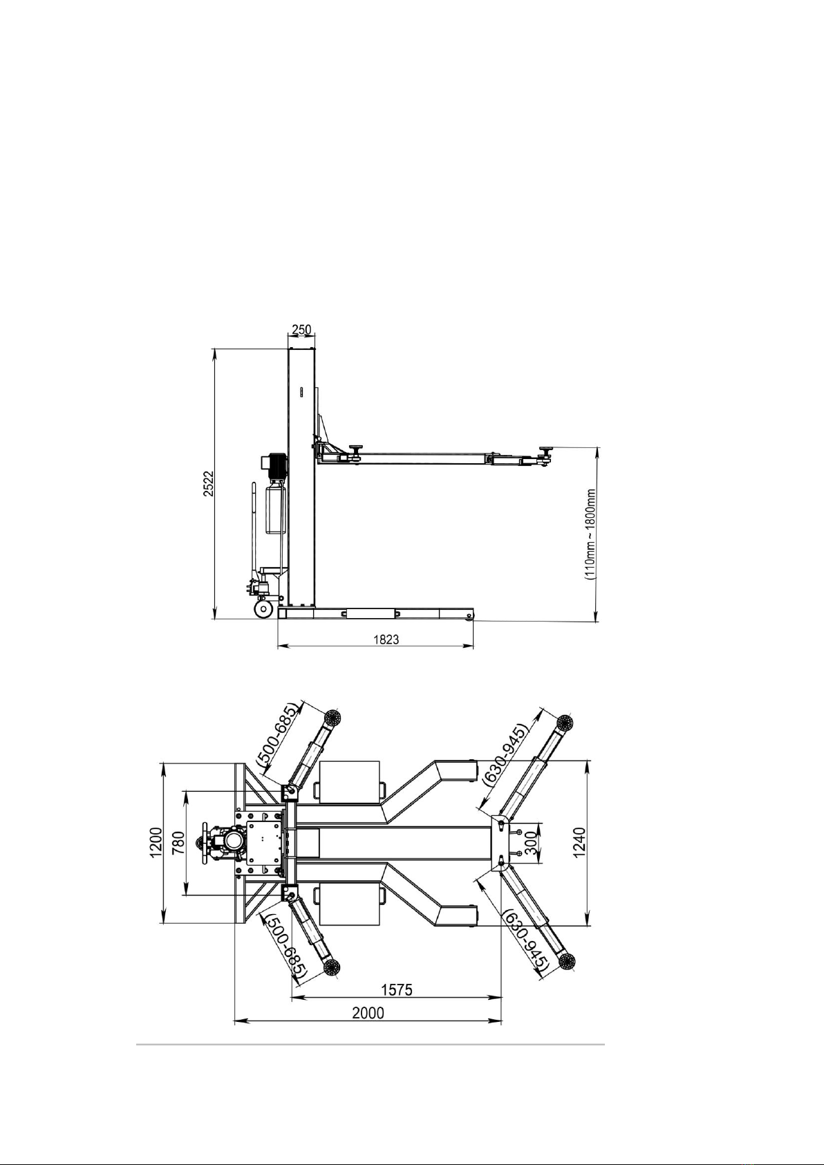
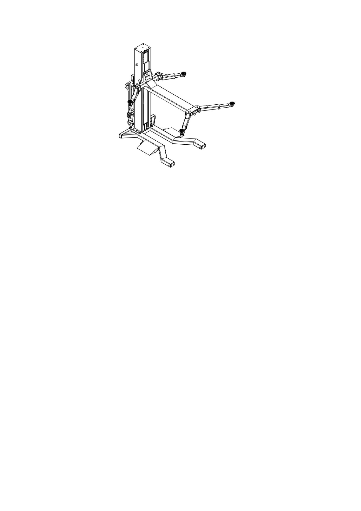
2. Structure Drawing: ...........................................................................................................4
3. Main Technical Mechanism Parameters Table.................................................................5
4. Packing, transport and storage....................................................................................5
4.1 Packing....................................................................................................................5
4.2 Lifting and handling .................................................................................................5
4.3 Storage and stacking of packages...........................................................................6
4.4 Delivery and check of packages..............................................................................6
5 Installation.........................................................................................................................6
5.1Working Site.............................................................................................................6
5.2 Installation ...............................................................................................................6
6. Operation instruction........................................................................................................7
6.1 Operation Rules for mechanism System .................................................................7
6.2 Operating Steps for Electrical Control System.........................................................7
6.3 Operation Flow:.......................................................................................................7
6.4 Use lifting arm..........................................................................................................9
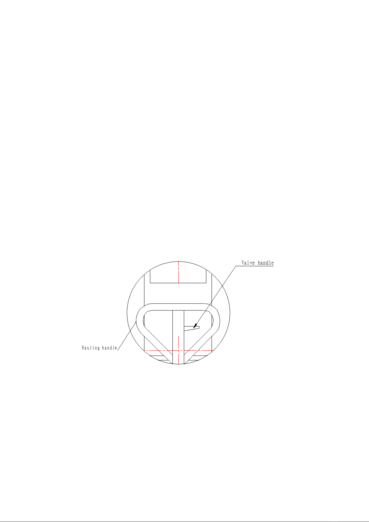
6.5 Control Unit............................................................................................................10
7. Maintenance and Troubleshooting.................................................................................10
7.1 Maintenance..........................................................................................................10
8. Troubleshooting.............................................................................................................11
Appendix............................................................................................................................13
1 Exploded drawing.....................................................................................................13
2 Circuit diagram .........................................................................................................14
3 Hydraulic diagram.....................................................................................................15

2
1Safety
1.1 Introduction
Thoroughly read this manual before operating the lift and comply with the instructions.
Always display the manual in a conspicuous location.
Personal injury and property damage incurred due to non-compliance with these safety
instructions are not covered by the product liability regulations.
1.2 Intended Use
This single column vehicle lift is classified as movable model. Movable single column
vehicle lift is specially useful for indoor. It is the special equipments for lifting vehicles, such
as cars, which park on ground, to a certain height for maintenance. It is forbidding to park
vehicles. Observe the rated load capacity and load distribution of the lift.
1.3 Safety Instructions for Commissioning
The lift may be installed and commissioned by authorized service personnel only.
The standard lift version may not be installed and commissioned in the vicinity of
explosives or flammable liquids, outdoors or in moist rooms (e.g. car wash).
1.4 Safety Instructions for Operation
Read the operating manual.
Lift operation by authorized personnel over 18 years only.
Always keep the lift and lift area clean and free of tools, parts, debris etc.
Once the disk adapters contact the lift points, check arm restraints for engagement.
After raising the vehicle briefly, stop and check the disk adapters for secure contact.
Always lift the vehicle using all four adapters.
Make sure the vehicle doors are closed during raising and lowering cycles.
Closely watch the vehicle and the lift during raising and lowering cycles.
Do not allow anyone to stay in lift area during raising and lowering cycles.
Do not allow anyone on lift or inside raised vehicle.
Only use the lift for its intended purpose.
Comply with the applicable accident prevention regulations.
Do not overload the lift. The rated load capacity is indicated on the lift nameplate.
Only use the vehicle manufacturer’s recommended lift points.
After positioning the vehicle apply the parking brake.

3
Use caution when removing or installing heavy components (center-of-gravity
displacement).
The main switch serves as emergency switch. In case of emergency turn to OFF
position.
Protect all parts of the electrical equipment from humidity and moisture.
Protect the lift against unauthorized usage by padlocking the main switch.
1.5 Safety Instructions for Servicing
Maintenance or repair work by authorized service personnel only.
Turn off and padlock the main switch before doing any maintenance, or repair work.
Work on pulse generators or proximity switches by authorized service personnel only.
Work on the electrical equipment by certified electricians only.
Ensure that ecologically harmful substances are disposed of only in accordance with
the appropriate regulations.
Do not use high pressure/steam jet cleaners or caustic cleaning agents.
Risk of damage!
Do not replace or override the safety devices.
1.6 Safety Features
1.6.1 Hold-to-run Type Control
The operator is required to hold the controls in the engaged position to raise or lower the lift.
1.6.2 Equalizing System
The lift is provided with distributing and connecting flow valve to ensure level movement of
both carriages.
1.6.3 Pipe Break Valve
The hydraulic cylinders are equipped with pipe break valves. They respond in case of rapid
pressure drop (line break) to prevent sudden lowering movements.
1.6.4 Pressure Relief Valve
A pressure relief valve is used to limit the hydraulic working pressure to a maximum of
200bar.
1.7 Disposal of used oil
Used oil, which is removed from the power unit and the plant during an oil change, must
be treated as a polluting product, in accordance with the legal prescriptions of the country
in which the lift is installed.
1.8 Machine demolition
The machine must be demolished by authorized technicians, just like for assembling. The
metallic parts can be scrapped as iron. In any case, all the materials deriving from the

4
demolition must be disposed of in accordance with the current standards of the country in
which the rack is installed. Finally, it should be recalled that for tax purposes, demolition
must be documented; submitting claims and documents according to the current laws in
the country in which the rack is installed at the time the machine is demolished.
2. Structure Drawing:

5
3. Main Technical Mechanism Parameters Table
Model
Name
Movable QJY-2.5-H
Lifting capacity:
2500kg
Max. lifting height
1800 mm
Lifting speed
24mm/s
Weight
750kg
Noise
<70 dB
Working environment
temperature
-5 ℃/+40℃
Working environment
Indoors
Power
1.5kw
Working voltage of
control system
24V
Voltage
110V/220V/380V/415V
Safety catch
Manual
4. Packing, transport and storage
Only skilled personnel who are familiar with the lift and this manual shall be allowed
to carry out packing, lifting, handling, transport and unpacking operations.
4.1 Packing
90% components were pre-assembled before shipment, and packed with blister packing in
steel frame. Arms, adapters and rubber pads were put in the lift. Power unit was packed in
carton box separately, power unit stand was packed and fixed on above the lifts.
4.2 Lifting and handling
When loading/unloading or transporting the equipment to the site, be sure to use suitable

6
loading (e.g. cranes, trucks) and hoisting means. Be sure also to hoist and transport the
components securely so that they cannot drop, taking into consideration the package’s size,
weight and centre of gravity and it’s fragile parts.
4.3 Storage and stacking of packages
Packages must be stored in a covered place, out of direct sunlight and in low humidity, at a
temperature between -10°C and +40°C.
4.4 Delivery and check of packages
When the lift is delivered, check for possible damages due to transport and storage; verify
that what is specified in the manufacturer’s confirmation of order is included. In case of
damage in transit, the customer must immediately inform the carrier of the problem.
Packages must be opened paying attention not to cause damage to people (keep a safe
distance when opening straps) and parts of the lift (be careful the objects do not drop from
the package when opening).
5 Installation
5.1Working Site
The user should prepare the working site for the lift before its arrival
5.1.1 Power Source The working site must be equipped with certain power. Install safety
distribution box with a 4-hole socket around the operation position.
5.1.2Ground The lift must be placed on flat and hard ground, which is made of cement or
bricks, with the load at the position of vertical post of 3t/m2.
5.1.3 Working Area There should be >about 1,000mm space around the vehicle
lifted, and the net height indoor is about 3600mm.
5.2 Installation
Because of the limitation of transportation, lift shall be disassembled to pack. The users
should assemble the lift according to the following figure:
Assemble movable single column lift
Overall assembly as follows:

7
6. Operation instruction
6.1 Operation Rules for mechanism System
6.1.1 The movable single column lift is provided with separate traveling mechanism.
Shake the hauling handle of the steering rear wheel forwards and backwards to
make the vertical column off the ground, then you can push or pull the lift. On arriving
the working site, press the valve handle to retract the wheel, then the vertical column
lands on the ground steadily.
6.1.2 The lift must only be pushed into the vehicle if in line with it. Insert the pallet under
the vehicle beam and the pallet must be in line with the beam.
6.1.3 Retract the rear wheel of vertical post to land the vertical post steadily before the lift
lifts load, and make sure there is no foreign article such as hand tools, bolts, screw
caps, small stones. No lifting during moving!
6.2 Operating Steps for Electrical Control System
New machine is operated for commissioning without load before its first use. The
electrical box is provided with “0-1”main power switch, which should be turned off
after the machine use finished.
6. 3 Operation Flow:

8
1) Vehicle stops in the service position with engine off
2) Turn the handle for hydraulic movable wheel to lift the vertical post base a bit
3) Push the lift into the underside of vehicle
4) Make sure there is no foreign articles under the base and the ground is level
5) Grasp the valve handle to make the base lowered to ground
6) Align 4 pallets on the lifting arm respectively to the supported positions on the vehicle
underside
7) Press the “green” button to raise the vehicle by 10~15 centimeters
8) Stop the vehicle raising and check for safe and secure four high points of the pallet.
9) Check if the main lifting arm touches the vehicle bottom plate, which should not occur
during normal lifting.
10) Pull the safety unlock handle to make the fliting platform unlocked.
11)To adjust lifting pad, turn it anticlockwise to make it rise ( adjustment distance of
100mm)
12)Press the “green” button again and pay attention to lifting arm and the vehicle lifted
until lifting is safe and reliable.
13)Raise the lift to the required height, then lower it to the lock position
14)After the repair of vehicle is finished, raise the lift about 2-3cm, pull the release calbe
on the column, then push the lowering handle on power unit to lower the lift.
15)Turn the handle of hydraulic pump and the lift is off the ground, pull out the lift.
16)Drive the vehicle away.

9
Movable lift pushed into the underside of the vehicle
Vehicle driving onto the lift
6.4 Use lifting arm
7.4.1 Movable Lift
a. According to the position under the vehicle chassis where the lifting arm is located,
the supporting arm on the lifting arm (close to the vertical post) may be pushed and
pulled up and down or to left and right:

10
b. The supporting arm in the front of lifting arm may be turned or pushed or pulled inward
or outward, or to left and right.
c.The height of pallet can be adjusted by turning it clockwise or anticlockwise.
6.5 Control unit
7 Maintenance and Troubleshooting
7.1 Maintenance
7.1.1 For daily maintenance and service of the lift, see operation steps, use and cautions
described in the previous page.
7.1.2 The working environment and the surface of this machine should be cleaned
usually.
7.1.3 During the use of this machine, if any oil leaking is found, check the leakage source.
Check whether the screw of the hydraulic oil hose is tighten, if it is loosen, it should
Release handle

11
be tighten. After this step, if the leaking problem still occurs, check whether the seal
kit of the cylinder is damaged, if it is damaged, it must be replaced.
7.1.4 Month Care
Below maintenance should be done once every month.
8 Troubleshooting
If lifting is impossible:
Check the power, interchange any two wires of three-phase wire and try lifting again.
Because the phase sequence of power does not conform to the adjusted phase
sequence when motor and pump is operating.
No.
Content of
maintenance
Method
Sample drawing
①
Check if the
rubber
pad of the arms
are damaged or not
New replacement
②
Check whether the
bolts, nuts, pins, etc.
on all parts are
normal
Reinforcement, clean-
up or new replacement
③
Check the shaft,
sprocket, chain, wire
wheels, wire rope
position whether
they are normal
Add butter lubrication,
re-adjust
④
Check the clean of
sliding parts and
safe insurance
situation
Add butter
Lubrication、re-adjust
or new replacement
⑤
Check hydraulic
system connections
and ensure no
leakage of fuel tank
Visual and tighten with
the wrench, and clean
oil

12
If lifting is possible but impossible to load 2.5T
Adjust the fluid valve. It is possible to press the “▲” button while turn the screw clockwise)
slowly, until the lifting arm rises.
If lifting is still impossible after above actions have been taken
Remove fluid valve and put it into diesel oil to wash. After that, install it again and operate
according to above action once more.
If there is any abnormal noise from hydraulic system during lifting
The hydraulic system may inhale air or the power voltage is too low. Check the oil level
and add oil if necessary. Move the cylinder up and down for several times to expel the air.

13
Appendix
1 Exploded drawing

14
NO.
NAME
QYT
NO.
NAME
QTY
1
top plate
1
42
Front arm out tube assembly
2
2
hexagonal screw
4
43
Fron arm assembly
2
3
washer
4
44
Toothed plate
2
4
spring washer
4
45
Plastic ball
4
5
Limit switch socket
1
46
handle
2
6
Limit switch
1
47
Pull rod
2
7
Column assembly
1
48
Rake tooth
2
8
Power unit
1
49
Hexagonal screw
2
9
Hexagon socket screw
4
50
spring
4
10
Washer
4
51
screw
1
11
Spring washer
8
52
nut
1
12
Trolley
1
53
axle
2
13
Chain pole for trolley
2
54
washer
2
14
Washer
2
55
Elastic collar
2
15
Axle for trolley
2
56
axle
2
16
Steel cable
1
57
washer
4
17
Spring
1
58
wheel
2
18
Safety assembly
1
59
Base plate assembly
1
19
Hoisting chain screw
1
60
cylinder
1
20
Hexagonal screw
1
61
Throttle valve
1
21
washer
1
62
Hydraulic hose
1
22
Spring washer
1
63
screw
8
23
Hexagonal screw
1
64
nut
8
24
Hexagonal screw
2
65
Elastic collar
4
25
Carriage
1
66
Pad nut
4
26
Nylon block(Ⅱ)
2
67
Thread socket
4
27
Nylon block(Ⅰ)
2
68
Pad weldment
4
28
Hexagonal screw
19
69
Rubber pad
4
29
Washer
19
70
screw
4
30
Spring washer
19
71
Bottom fix plate
1
31
Hexagonal screw
2
72
Cover for column
1
32
elastic collar
2
73
Top fix plate
1
33
bearing
2
74
hook
2
34
Wheel
2
75
washer
2
35
Elastic collar
2
76
Spring washer
2
36
Screw
4
77
nut
2
37
Axle for rear arm
2
78
Elevator chain
1
38
Rear arm out tube
assembly
2
79
Yoke with roller
1
39
Rear arm assembly
2
80
yoke
1
40
Long arm assembly
1
81
Oiless bearing
1
41
Front arm axle
2
82
Ascension shaft
1

15
2 Circuit diagram
3 Hydraulic diagram
No
Name
No
Name
No
Name
1
Tank
5
Start buffer valve
9
Relief valve
2
Filter
6
One-way valve
10
Anti-explosion valve
3
Oil pump
7
Release valve
11
4
Motor
8
Return oil throttle valve
Table of contents
Other Castex Lifting System manuals
Popular Lifting System manuals by other brands

Harmar Mobility
Harmar Mobility AL625 Installation & owner's manual

HPA
HPA HELPER ALLY 30 Operator's manual

probst
probst TSZ-MAXI operating instructions

haacon
haacon 1889.10 quick start guide

Oshkosh Corporation
Oshkosh Corporation JLG AE1932 Service maintenance manual

ATH-Heinl
ATH-Heinl Single Lift 35M operating instructions

morse
morse 82H-125 Operator's manual

AUTEC
AUTEC ALM-6040FL User & installation manual

Savaria
Savaria Ceiling Lift Track Bridge owner's manual

Genie
Genie GTH-4013 EX Operator's manual

Motorline professional
Motorline professional CHAINLIFT User& installer's manual

Bishamon
Bishamon X Series Operation and service manual