manuals.online logo
Brands
  1. Home
  2. •
  3. Brands
  4. •
  5. Cateye
  6. •
  7. Bicycle Accessories
  8. •
  9. Cateye CC-RD400DW User manual

Cateye CC-RD400DW User manual

CATEYE STRADA DOUBLE WIRELESS
CYCLOCOMPUTER CC-RD400DW
0678
U�S� Pat� Nos� 5236759/6957926 Pat�/Design Pat� Pending
Copyright© 2008 CATEYE Co�, Ltd�
CCRD4DW-081030 066600620 2
ENG
Tire circumference
reference table
Tire size
L (mm)
12 x1.75 935
12 x1.95 940
14 x1.50 1020
14 x1.75 1055
16 x1.50 1185
16 x1.75 1195
16 x2.00 1245
16 x1-1/8 1290
16 x1-3/8 1300
17 x1-1/4 (369) 1340
18 x1.50 1340
18 x1.75 1350
20 x1.25 1450
20 x1.35 1460
20 x1.50 1490
20 x1.75 1515
20 x1.95 1565
20 x1-1/8 1545
20 x1-3/8 1615
22 x1-3/8 1770
22 x1-1/2 1785
24 x1 (520) 1753
24 x 3/4 Tubular 1785
24 x 1-1/8 1795
24 x 1-1/4 1905
24 x 1.75 1890
24 x 2.00 1925
24 x 2.125 1965
26 x 7/8 Tubular 1920
26 x 1 (571) 1952
26 x 1-1/8 1970
26 x 1-3/8 2068
26 x 1-1/2 2100
26 x 1.0 (559) 1913
26 x 1.25 1950
26 x 1.40 2005
26 x 1.50 2010
26 x 1.75 2023
26 x 1.95 2050
26 x 2.00 2055
26 x 2.1 2068
26 x 2.125 2070
26 x 2.35 2083
26 x 3.00 2170
27 x 1 (630) 2145
27 x 1-1/8 2155
27 x 1-1/4 2161
27 x 1-3/8 2169
650 x 20C 1938
650 x 23C 1944
650 x 35A 2090
650 x 38A 2125
650 x 38B 2105
700 x 18C 2070
700 x 19C 2080
700 x 20C 2086
700 x 23C 2096
700 x 25C 2105
700 x 28C 2136
700 x 30C 2146
700 x 32C 2155
700C Tubular 2130
700 x 35C 2168
700 x 38C 2180
700 x 40C 2200
700 x 44C 2224
29 x 2.1 2288
29 x 2.3 2326
Preparing the computer
1Clear all data (initialization)
Press the AC button on the back�
2Select the speed units
Select “km/h” or “mph”�
3Enter the tire circumference
Enter the tire circumference of your bicycle in mm�
Refer to the tire circumference reference table�*
4Set the sensor ID
Place the computer near the sensor� Pressing & hold-
ing RESET on the sensor displays the ID number on the
screen, then moves to clock setting�
When setting the sensor ID, place the sensor at least 20 cm (ap-*
proximately 8 inches) away from the computer� Press and hold the
RESET button, the sensor will send the ID when releasing the button�
While setting the ID, the computer is on Standby for 5 minutes� If the com-*
puter does not receive any sensor signal, or you press and hold MODE during
Standby, “ERROR” is displayed and the ID is canceled� You can continue to set
up, but cannot measure� Be sure to set the ID according to “Sensor ID Setting”
on the menu screen�
When the ID has been already set, the original ID is applied if you cancel the ID�*
5Set the clock
When MODE is pressed and held, “Displayed time”,
“Hour”, and “Minute” will appear, in this order�
AC
MENU
MODE
Before using the computer, please thoroughly read this manual and keep
it for future reference.
This device complies with Part 15 of the FCC Rules� Operation is subject to the following two condi-
tions:(1)This device may not cause harmful interference, and (2) this device must accept any interfer-
ence received, including interference that may cause undesired operation�
Modifications The FCC requires the user to be notified that any changes or modifications made to this device
that are not expressly approved by CatEye Co�, Ltd� May void the user ’s authority to operate the equipment�
AC
km/h ↔mph
Increase
the value
Move digits (by
pressing & holding)
Register the setting
Register the
setting
Register the
setting (finish)
Move to Clock
Setting when no
ID has been set.
Start the ID Set-
ting (by pressing
& holding)
24h↔12h,
or increase
the value
Switch the screen
or move digits (by
pressing & holding)
Cancel the ID or
reset (by press-
ing & holding)
MENUMENU
MENUMENU
MODEMODE
MODEMODE
MODEMODE
MENUMENU
MENUMENU
MODEMODE
MODEMODE
MODEMODE
Battery case cover
Push!
When the computer is
mounted on the bracket
km/h mph : Speed unit : Wheel size icon
: Sensor signal reception icon
RESET
9
9
20 - 100 cm20 - 100 cm
1
2
3
4
5 mm5 mm
3 mm
3 mm
3
7
6
5
3 mm
5 mm
1
2
2
1
4
8
8
2
How to install the unit on your bicycle
5
4
6
7
8
9
2
1
3
Bracket band
1
Bracket
2
Sensor
3
(Speed/Cadence)
Nut
4
Wheel magnet
5
Cadence magnet
6
S
7
ensor rubber pad
B
8
racket rubber pad
Nylon ties (x3)
9
Install the sensor and magnet
The clearance between the sensor face and mag-
net is less than 5 mm for Speed and 3 mm for
Cadence, respectively�
The magnet faces the sensor zone of the sensor�
The distance between the computer
and sensor is within the transmis-
sion range, and the mark on the
sensor points to the computer�
A
Temporarily install the sensor / wheel magnet / cadence magnet
Adjust and fix the clearance between the magnet and sensor
Rear wheel spoke
Left Chain StayLeft crank
Attach the bracket to the stem or handlebar
When attaching the bracket to the stem
When attaching the bracket to the handlebar
On account of the receiving sensitivity, attach the*
bracket so that the computer is kept horizontal�
Click
While supporting it by hand,
push it out as if lifting the front up
Cut
Caution:
Round off the cut edge
of the bracket band to
prevent injury�
B
C
Temporarily install the sensor and 2 magnets at the respective points that satisfy the condition* B�
When the condition cannot be satisfied, move the sensor in the front-and-rear direction to adjust�
Loosen the sensor screw to adjust the speed� After adjustment, firmly tighten the sensor screw and nylon tie to fix�*
Remove/install the
computer
After installment, check that the speed is displayed when gently turning the rear wheel, whereas the cadence (* C) is
displayed when turning the crank�
When the sensor ID has not been set, set the ID according “Sensor ID setting” on the menu screen�*
Sensor zone
Sensor
Sensor zone
The wheel magnet may be installed anywhere on the*
spoke if the above installation conditions are satisfied�
Cadence
magnet
Wheel magnet
Cadence
magnet Wheel magnet
Cadence
Speed
Sensor screw
For wing type handlebar or oversized stem, bracket can be*
mounted using the bracket holder and nylon ties� (Option parts)
Stem
Handlebar
L mm
Measure wheel circumference (L) of your bike
To get the most accurate calibration do a wheel roll out. With the valve stem perpendicular to the ground, mark the
pavement at the valve stem. With the riders weight on the bike, roll the wheel one tire revolution in a straight line and
mark the ground when the valve stem is perpendicular to the ground again. Measure the distance in millimeters. This
is the most accurate wheel calibration number.
WARNING / CAUTION
Do not concentrate on the computer while riding� Ride safely!•
Install the magnet, sensor, and bracket securely� Check these periodically�•
If a child swallows a battery, consult a doctor immediately�•
Do not leave the computer in direct sunlight for a long period of time�•
Do not disassemble the computer�•
Do not drop the computer to avoid malfunction or damage�•
When using the computer installed on the bracket, change the•MODE by pressing on the three dots below the
screen� Pressing hard on other areas can result in malfunction or damage to the computer�
Tighten the dial on the FlexTight bracket by hand only� Over-tightening can damage the bracket threads�•
When cleaning the computer, bracket and sensor, do not use thinners, benzene, or alcohol�•
Dispose of used batteries according to local regulations�•
LCD screen may be distorted when viewed through polarized sunglass lenses�•
Wireless Sensor
In order to prevent any interference with the sensor signal, the transmission range is designed to
be 20 to 100 cm, in addition to use of the ID code� (This receiving range is only a reference�) Please
note the following points�
To use this unit, the sensor ID has to be set�•
Two different IDs,•ID1 and ID2, can be registered to this unit, which are identified automatically�
The computer cannot receive the signal when the distance between the sensor and computer is too long�•
Temperature drop and battery drain may worsen the receiving sensitivity even if they are within the trans-
mission range�
Interference may occur, resulting in incorrect data, if the computer is:
Near a TV, PC, radio, motor, or in a car or train�•
Close to a railroad crossing, railway tracks, TV stations and/or radar base�•
Using with other wireless devices, or some particular battery lights�•
ENG
CC-RD400DW
Standard parts Option parts
MODEMODE
MODEMODE
MODEMODE
MODEMODE
MODEMODE
MODEMODE
MENUMENU
*1
MODE
Wheel selection ������� Toggle between the specified wheel size (tire circumference) and �
Use this function if the computer is to be shared between two bicycles�
Pressing MODE toggles between and �
Wheel size entry ������ Pressing MODE increases the value, and pressing and holding MODE moves
to the next digit�
To enter the wheel size
* , display using “Wheel selection”�
Sensor ID setting������ Pressing MODE changes to ID1 or ID2, and pressing and holding MODE moves to
Standby� To set the ID, refer to “Preparing the computer-4�”
ID2* is used when the computer is shared with the second sensor� The computer
identifies ID1 and ID2 automatically�
Clock setting������������� To set the clock, refer to “Preparing the computer-5”�
Total distance manual entry
���������������������������������� Before reinitializing the computer, note the total distance�
This reading will later allow you to enter the total distance manually�
Speed unit ���������������� Pressing MODE toggles between km/h and mph�
Maintenance
To clean the computer or accessories, use diluted neutral detergent on a soft cloth, and wipe it off
with a dry cloth�
Replacing the battery
Computer
Replace the battery when the digit of the selected Mode
flashes� Install a new lithium battery (CR2032) with the (+) side
facing upward� Then reinitialize the computer referring to “Preparing
the computer”�
When the battery is installed, place the seal with the “TOP” side up-*
ward�
Sensor
Replace the battery when the Speed digit flashes� After replacement,
check the positions of the sensor and magnet�
After the battery is replaced, ID setting is required again� For details, refer to*
“Sensor ID setting” on the menu screen�
TOP
TOP
COIN
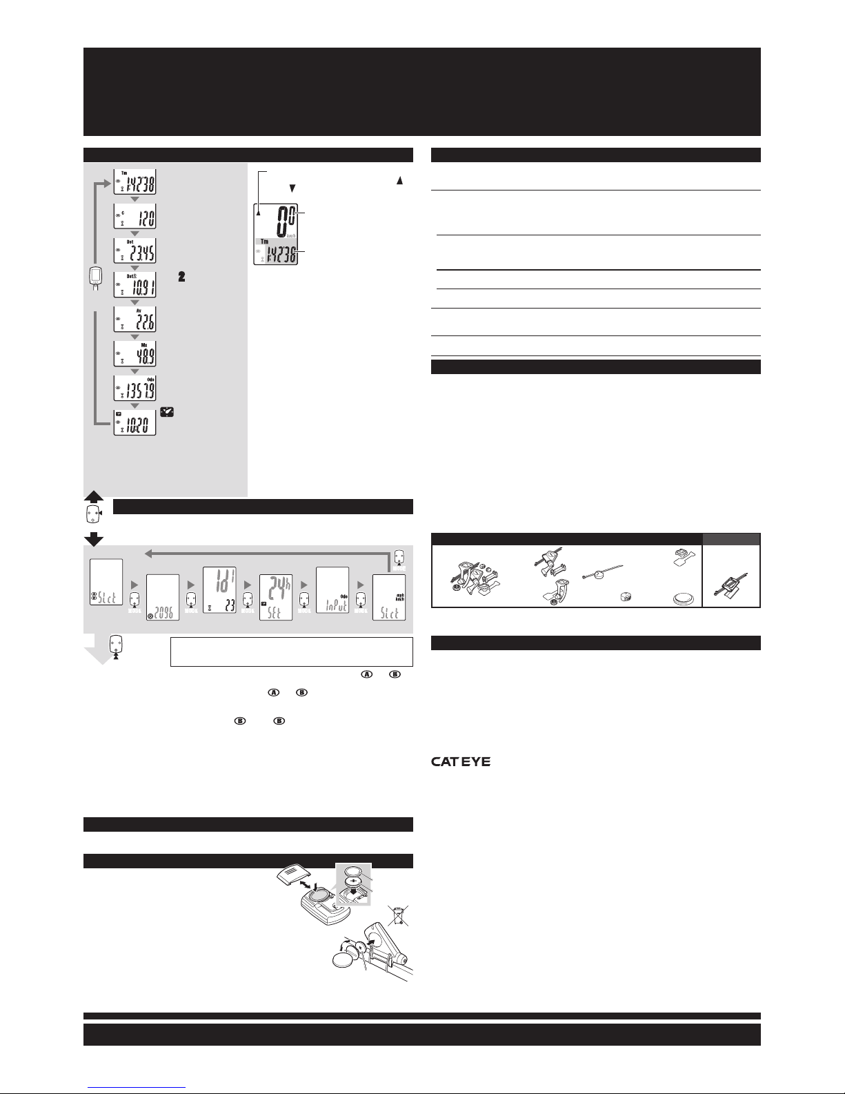
Starting/Stopping measurement
Measurements start automatically when the bicycle
is in use� During measurement, km/h or mph
flashes�
Switching computer function
Pressing MODE switches function, in order, as
shown on the left�
Resetting data
To reset measurement data, display any data other
than for Dst-2 and then press and hold MODE�
Pressing and holding MODE with Dst-2 displayed
resets Dst-2 only� The total distance is never reset�
Power-saving function
If the computer has not received a signal for 10 min-
utes, power-saving mode will activate and only the
clock will be displayed� When the computer receives a
sensor signal again, the measuring screen reappears�
If 60 minutes’ inactivity elapses, power-saving mode
will change to SLEEP mode� Pressing the MODE in
SLEEP mode brings up the measuring screen�
Changing the computer settings [menu screen]
If the MENU is pressed with the measuring screen displayed, the menu screen appears�
Press the MODE when measurement has stopped and no signal is being received to
change menu settings�
Operating the computer [Measuring screen]
Wheel selection
Wheel size entry
Sensor ID setting
Clock setting
Total distance manual entry
Speed unit
CR2032
Seal
Push!
CR2032
Pace arrow
Indicates whether the current speed is faster ( ) or
slower ( ) than the average speed.
Current speed
0.0(4.0) - 105.9 km /h
[0.0(3.0) - 65.9 mph]
Selected Mode
With the computer installed on the bracket,*1
press on the three raised dots on the face of
the computer�
If*2 Tm exceeds approximately 27 hours or Dst
exceeds 999�99 km, .E (Error) is displayed as
the average speed� Reset data�
Tm Elapsed Time
0:00’00” - 9:59’59”
Dst Trip Distance
0�00 - 999�99 km [mile]
CCadence
0(20) - 299 rpm
Dst2Trip Distance-2
0�00 - 999�99 /
1000�0 - 9999�9 km [mile]
Av
Average Speed*2
0�0 - 105�9 km/h
[0�0 - 65�9 mph]
Mx
Maximum Speed
0�0(4�0) - 105�9 km/h
[0�0(3�0) - 65�9 mph]
Odo Total Distance
0�0 - 9999�9 /
10000 - 99999 km [mile]
Clock
0:00 - 23:59
or 1:00 - 12:59
MODEMODE
Setting change
(by pressing &
holding)
After changing, be sure to press* MENU to register the setting�
If the menu screen is not touched for a minute, the Measuring screen reap-*
pears without data changes�
Troubleshooting
MODE does not work when the computer is mounted on its bracket.
Check that there is no dirt between the bracket and the computer.
Wash off the bracket with water to get rid of any dirt, and to ensure that the computer slides in and out smoothly�
The Sensor signal reception icon does not flash (the speed or cadence is not displayed). Move the
computer near the sensor, and turn the rear wheel or crank. If the Sensor signal reception icon flashes,
this trouble may be due to battery drain, not any malfunction.
Set the sensor ID.
Set the ID according to “Sensor ID setting” on the menu screen�
Check that the clearance between each sensor and magnet is not too large. (Clearance: less than 5 mm for Speed, and 3 mm for
Cadence)
Check that the magnet goes through the relevant sensor zone.
Adjust the positions of the magnet and sensor�
Check that the distance between the computer and sensor is correct (Distance: within 20 to 100 cm)
Install the sensor within the specified range�
Is the computer or sensor battery weak? In winter, battery performance diminishes.
Replace with new batteries� After replacement, follow the procedure “Replacing the battery�”
No display.
Is battery in the computer run down?
Replace it� Then reinitialize the computer referring to “Preparing the computer”�
Incorrect data appear.
Reinitialize the computer referring to “Preparing the computer”�
Specification
Battery........................... Computer : Lithium battery (CR2032) x 1
Sensor : Lithium battery (CR2032) x 1
Battery life.....................Computer : Approx. 1 years (If the computer is used for 1 hour/day; the battery life will vary depending on the conditions
of use.)
Sensor : Approx. 6 months (If the computer is used for 1 hour/day; the battery life will vary depending on the condi-
tions of use.)
This is the average figure of being used under 20 °C temperature and the distance between the computer*
and the sensor is 100 cm�
Controller...................... 8-bite, 1-chip microcomputer (Crystal controlled oscillator)
Display.......................... Liquid crystal display
Sensor...........................No contact magnetic sensor
Transmission distance...Between 20 and 100 cm
Wheel circumference range
......................................0100 mm - 3999 mm (Default figure A: 2096 mm, B: 2096 mm)
Working temperature.....32 °F - 104 °F (0 °C - 40 °C) (This product will not display appropriately when exceeding the Working Temperature
range. Slow response or black LCD at lower or higher temperature may happen respectively.)
Dimensions/weight .......Computer : 1-53/64” x 1-7/32” x 5/8” (46.5 x 31 x 16 mm) / 0.78 oz (22 g)
Sensor : 1-63/64” x 2-55/64” x 45/64” (50.5 x 72.5 x 17.7 mm) (Excluding the arm) / 1.06 oz (30 g)
The factory-loaded battery life might be shorter than the above-mentioned specification�*
The specifications and design are subject to change without notice�*
#160-2790
Parts kit
#160-2780
Sensor
#160-0280
Bracket band
#160-2770
Bracket holder
#166-5150
Lithium battery
(CR2032)
#169-9691
Wheel magnet
#169-9766
Cadence magnet
#160-2193
Bracket
LIMITED WARRANTY
2-Year Computer only
(Accessories/Bracket sensor and Battery Consumption excluded)
CatEye cycle computers are warranted to be free of defects from materials and workmanship for a period
of two years from original purchase� If the product fails to work due to normal use, CatEye will repair or
replace the defect at no charge� Service must be performed by CatEye or an authorized retailer�
To return the product, pack it carefully and enclose the warranty certificate (proof or purchase) with instruc-
tion for repair� Please write or type your name and address clearly on the warranty certificate�
Insurance, handling and transportation charges to CatEye shall be borne by person desiring service�
For UK and REPUBLIC OF IRELAND consumers, please return to the place of purchase� This does not af-
fect your statutory rights�
CO., LTD.
2-8-25, Kuwazu, Higashi Sumiyoshi-ku, Osaka 546-0041 Japan
Attn: CATEYE Customer Service Section
Service & Research Address for USA
CATEYE Service and Research Center
1705 14th St� 115 Boulder, CO 80302
Phone : 303�443�4595
Toll Free : 800�5CATEYE
Fax : 303�473�0006
E-mail : service@cateye�com
URL : http://www�cateye�com

Other manuals for CC-RD400DW

2

This manual suits for next models

2

Other Cateye Bicycle Accessories manuals

Cateye STRADA CC-RD100N User manual

Cateye

Cateye STRADA CC-RD100N User manual

Cateye Strada Smart CC-RD500B Setup guide

Cateye

Cateye Strada Smart CC-RD500B Setup guide

Cateye Velo Wireless User manual

Cateye

Cateye Velo Wireless User manual

Cateye Single Shot Plus HL-EL610RC User manual

Cateye

Cateye Single Shot Plus HL-EL610RC User manual

Cateye RAPID X2 KINETIC User manual

Cateye

Cateye RAPID X2 KINETIC User manual

Cateye PADRONE DIGITAL CC-PA400B User manual

Cateye

Cateye PADRONE DIGITAL CC-PA400B User manual

Cateye Strada Digital Wireless CC-RD420DW User manual

Cateye

Cateye Strada Digital Wireless CC-RD420DW User manual

Cateye CC-RD400DW User manual

Cateye

Cateye CC-RD400DW User manual

Cateye COMMUTER CC-COM10W User manual

Cateye

Cateye COMMUTER CC-COM10W User manual

Cateye CC-TR100 User manual

Cateye

Cateye CC-TR100 User manual

Cateye MICRO Wireless CC-MC100W User manual

Cateye

Cateye MICRO Wireless CC-MC100W User manual

Cateye Micro CC-6000 User manual

Cateye

Cateye Micro CC-6000 User manual

Cateye CC-ED200N User manual

Cateye

Cateye CC-ED200N User manual

Cateye Strada Digital Wireless CC-RD420DW User manual

Cateye

Cateye Strada Digital Wireless CC-RD420DW User manual

Cateye Tomo CC ST-200 User manual

Cateye

Cateye Tomo CC ST-200 User manual

Cateye OS 1.1 User manual

Cateye

Cateye OS 1.1 User manual

Cateye Astrale 8 User manual

Cateye

Cateye Astrale 8 User manual

Cateye PADRONE DIGITAL Operating instructions

Cateye

Cateye PADRONE DIGITAL Operating instructions

Cateye CC-CD300DW User manual

Cateye

Cateye CC-CD300DW User manual

Cateye CR123A User manual

Cateye

Cateye CR123A User manual

Cateye TL-LD1000 Use and care manual

Cateye

Cateye TL-LD1000 Use and care manual

Cateye PADRONE SMART User manual

Cateye

Cateye PADRONE SMART User manual

Cateye ENDURO 2 User manual

Cateye

Cateye ENDURO 2 User manual

Cateye WEARABLEX SL-WA100 User manual

Cateye

Cateye WEARABLEX SL-WA100 User manual

Popular Bicycle Accessories manuals by other brands

BONSAI VELOCITY OM-812 PRODUCT INFORMATION AND INSTRUCTIONS

BONSAI VELOCITY

BONSAI VELOCITY OM-812 PRODUCT INFORMATION AND INSTRUCTIONS

ANSMANN RM7.0 Original operating instructions

ANSMANN

ANSMANN RM7.0 Original operating instructions

Acumen VETTA RT233 manual

Acumen

Acumen VETTA RT233 manual

SRAM Rock Shox Yari 2019 Service manual

SRAM

SRAM Rock Shox Yari 2019 Service manual

Shimano XTR Service instructions manual

Shimano

Shimano XTR Service instructions manual

Stan's NoTubes OE Series Instruction guide

Stan's

Stan's NoTubes OE Series Instruction guide

COPLATE B-TFL17 manual

COPLATE

COPLATE B-TFL17 manual

Widek Qibbel Air User instructions

Widek

Widek Qibbel Air User instructions

Kody Technologies 101-017 Installation instruction

Kody Technologies

Kody Technologies 101-017 Installation instruction

Surly ASTM 3 Framesheet

Surly

Surly ASTM 3 Framesheet

SRAM Rock Shox TwistLoc user manual

SRAM

SRAM Rock Shox TwistLoc user manual

Kemo M172 quick start guide

Kemo

Kemo M172 quick start guide

SR Suntour SR Suntour owner's manual

SR Suntour

SR Suntour SR Suntour owner's manual

Woosh GSM CD Kit Fittings guide

Woosh

Woosh GSM CD Kit Fittings guide

Magura Marta SL Magnesium Series Workshop manual

Magura

Magura Marta SL Magnesium Series Workshop manual

Topeak NINJA CO2+ user guide

Topeak

Topeak NINJA CO2+ user guide

Yolin YL80C user manual

Yolin

Yolin YL80C user manual

Trek INCITE 6i Installation

Trek

Trek INCITE 6i Installation

manuals.online logo
manuals.online logoBrands
  • About & Mission
  • Contact us
  • Privacy Policy
  • Terms and Conditions

Copyright 2025 Manuals.Online. All Rights Reserved.