Cathode Lighting Systems FCLS-Slim User manual

Installation Manual Page 1
Models FCLS-Slim & HFCLS-Slim
(Regular & High Efficiency Flexible Cathole Light Strip)
For indoor dry or protected indoor damp location installation only.
Operating temperature range 55º F to 90ºF.
Patent 6,454,431
Patent 7,293,895
8020 Queenair Drive, Gaithersburg, MD 20879 USA • phone: 301 921 4120 • fax: 301 963 3050
©2011 Cathode Lighting Systems Inc.
SECTION
FCLS-Slim Manual 8-11
E168380
INDEX Page 1: Introduction
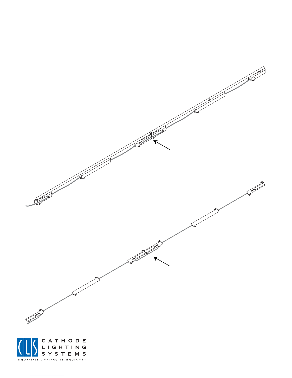
Page 2: Typical luminaire configuration
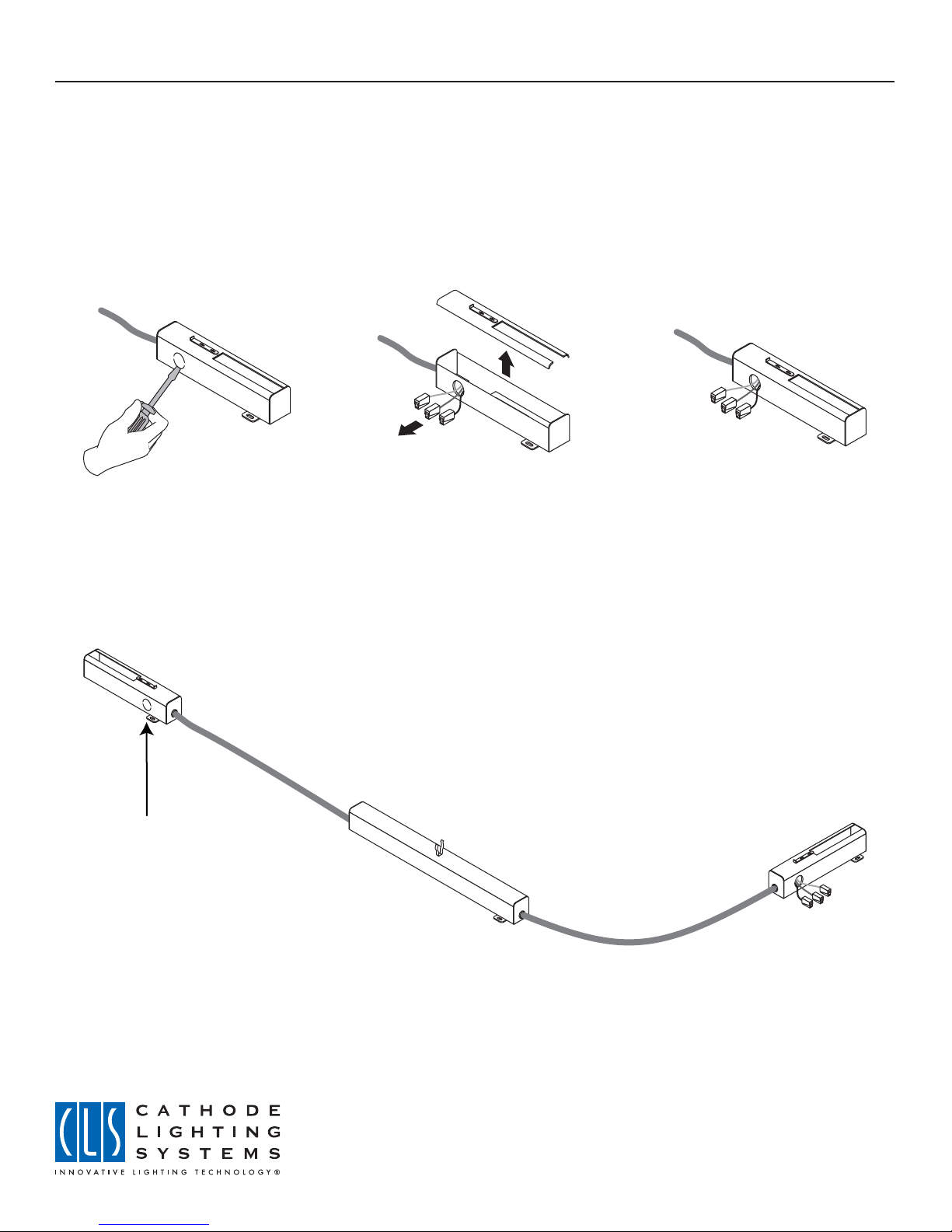
Page 3: Preparing the luminaire for installation
Page 4 & 5: Installation sequence overview
Page 6 & 7: Mounting the luminaire
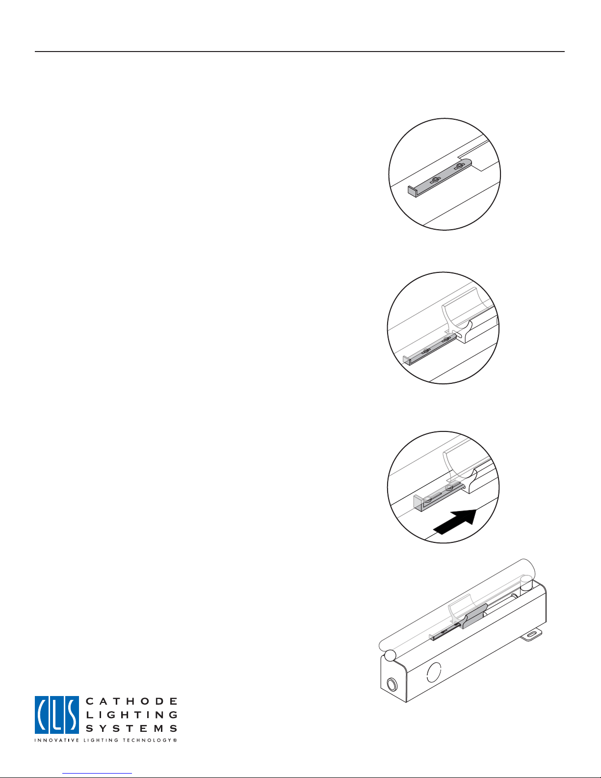
Page 8: Lamp lock feature
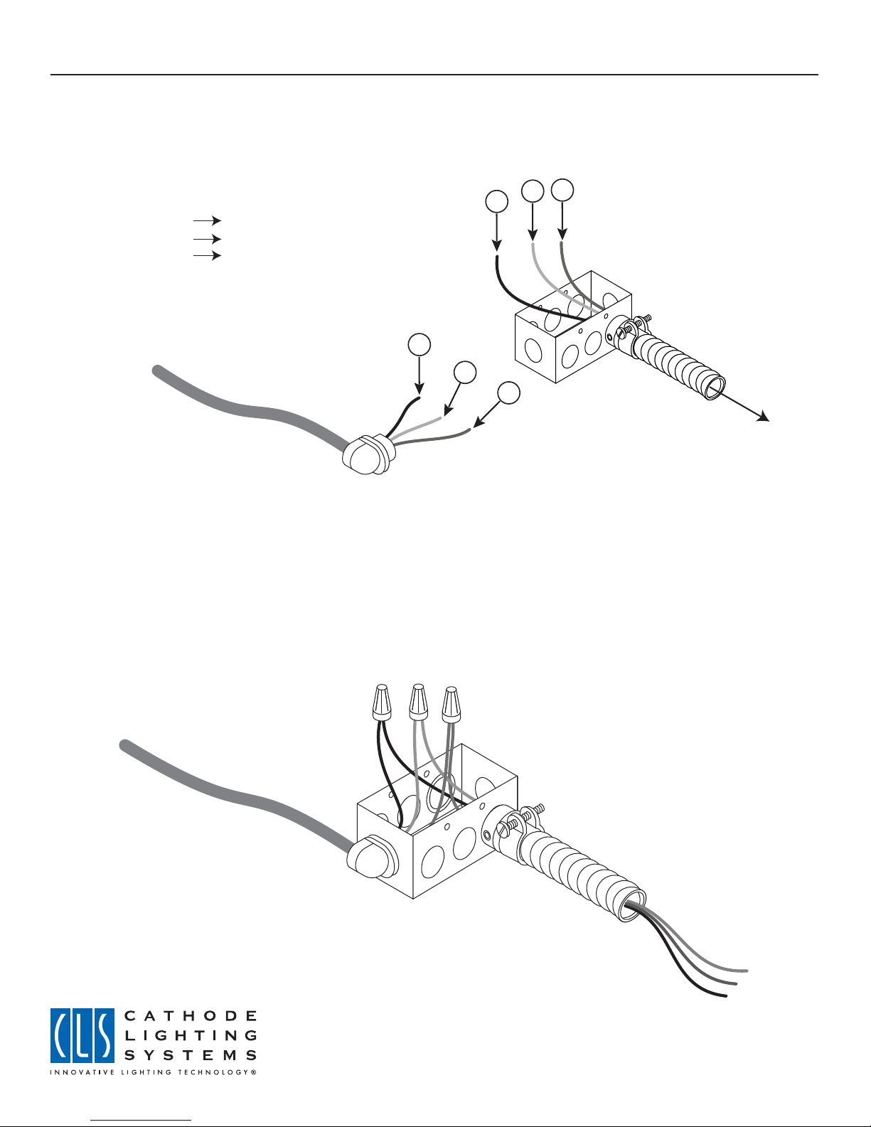
Page 9: Connection to the branch circuit
Page 10: Wiring diagram
Page 11: Electrical Information / Checklist / Troubleshooting
PLEASE READ THIS MANUAL THOROUGHLY PRIOR TO INSTALLING THIS LUMINAIRE
WARNING: These luminaires are to be installed in surface-mounted, non-concealed locations only. They may
not be recessed into the building structure. No part of the luminaire may be concealed behind drywall, permanent
ceiling, or any other similar structure.
This luminaire must be installed by a licensed electrical contractor, and must be installed in accordance with all
applicable local, and national electric codes.
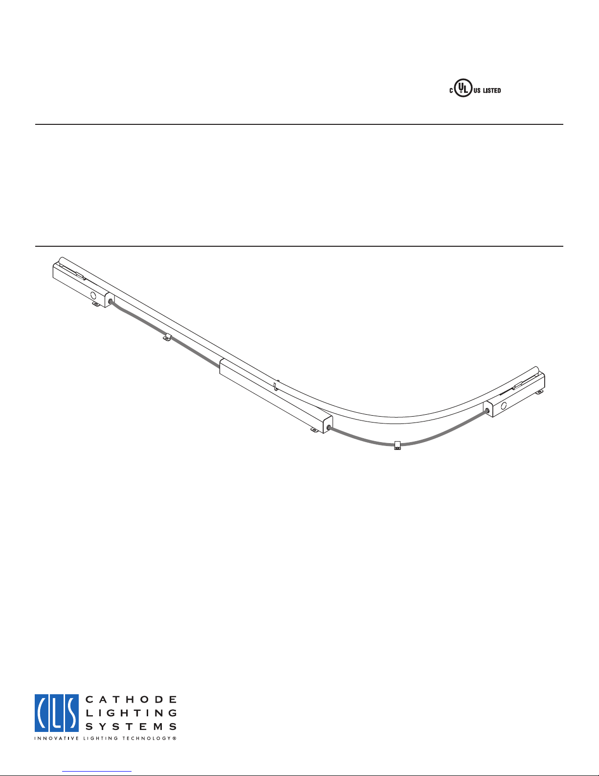
This flexible cold cathode fluorescent luminaire has been designed to allow a single flexible luminaire to be utilized
with a variety of cold cathode lamp shapes and sizes. The modular connection method used to electrically wire
one luminaire to the next allows for rapid installation. Each luminaire is composed of three anodized aluminum
enclosures, permanently connected by two lengths of flexible electrical cord. The middle enclosure contains the
ballast. The two end-enclosures each contain a lampholder into which lamp ends are inserted and electrically
connected. A jumper cable to interconnect luminaires is provided with each luminaire. Utilizing electrical quick
connects and snap-in strain reliefs, the jumper cable is connected to an adjacent luminaire to the branch circuit.
Integral mounting brackets are incorporated into each of the aluminum enclosures, allowing the electrician to
mount the luminiares with the lamps in place.

Installation Manual Page 2
8020 Queenair Drive, Gaithersburg, MD 20879 USA • phone: 301 921 4120 • fax: 301 963 3050
©2011 Cathode Lighting Systems Inc.
FCLS-Slim Manual 8-11
Overhead view of a section
of luminaires, without lamps installed.
Perspective view of a section of
luminaires, with lamps installed.
Jumper cable
Jumper cable
TYPICAL LUMINAIRE CONFIGURATION
The FCLS-Slim is a flexible fluorescent luminaire, and can be configured in the field to accommodate straight,
curved or bent lamps from Cathode Lighting Systems. Interconnections are made externally from one luminaire to
the next using modular jumper cable assemblies which install quickly and easily.

Installation Manual Page 3
8020 Queenair Drive, Gaithersburg, MD 20879 USA • phone: 301 921 4120 • fax: 301 963 3050
©2011 Cathode Lighting Systems Inc.
FCLS-Slim Manual 8-11
PREPARING THE LUMINAIRE FOR INSTALLATION
Luminaires are shipped pre-assembled from the factory. The only field preparation required is that the pryouts at
the end of each luminaire must be removed and the quick-connect wiring inside must be withdrawn so that it may
be connected to the pre-assembled jumper cables. In some instances, a luminaire (or array of luminaires) will
terminate, and no wiring will be required into the last enclosure. The pryouts are intended to be left undisturbed in
these situations.
Step No. 1:
Remove pryout
Step No. 2:
Remove snap-on cover, discard
pryout slug and careully feed the
three quick connect terminals and
wire through the open hole
Step No. 3:
Replace snap-on cover
Pryouts are to be left in
place if no wiring is required
into the end of a luminaire

Installation Manual Page 4
8020 Queenair Drive, Gaithersburg, MD 20879 USA • phone: 301 921 4120 • fax: 301 963 3050
©2011 Cathode Lighting Systems Inc.
FCLS-Slim Manual 8-11
INSTALLATION SEQUENCE OVERVIEW
This luminaire is designed to be daisy-chained together, using a pre-assembled jumper (to connect one luminaire to
the next) and quick connect terminals which allow for tool-free wiring. All luminaires are shipped from the factory
with internal quick wiring terminals which must be relocated so that they are accessable from the luminaire’s
exterior. Once they have been relocated, they are connected to the jumper cable and then re-inserted back into
the luminaire.
Step No. 1:
Insert lamp
Step No. 2:
Mount luminaire
Step No. 3:
Connect jumper wires to quick connect terminals: Black to Black (hot) , White to White (neutral) and Green to
Green (ground)
Step No. 4:
Carefully install wiring back into luminaire and push snap-in strain relief into the hole until it clicks into place.
Jumper may now be connected to the adjacent luminaire or to the branch circuit.
B
A
Pre-assembled
jumper cable
AB

Installation Manual Page 5
8020 Queenair Drive, Gaithersburg, MD 20879 USA • phone: 301 921 4120 • fax: 301 963 3050
©2011 Cathode Lighting Systems Inc.
FCLS-Slim Manual 8-11
INSTALLATION SEQUENCE OVERVIEW (Continued)
Shown below are schematics of the two typical configurations which utilize the jumper cable.
Wiring to an adjacent luminaire
Step No. 1:
After luminaires have been mounted in place, make the
electrical connections, using the integral quick connect
fittings.
Step No. 2:
Push the connections carefully back into the luminaire
and snap the strain relief fittings into the luminaire.
Step No. 3:
The completed connection
Wiring from the luminaire to the branch circuit
Step No. 1:
With one end of the jumper cable attached and
electrically connected to the luminaire, snap the
strain relief into the 1/2” (trade size) pryout in the
junction box
Step No. 2:
Using UL-listed wire connectors, connect:
• the black lead of the jumper cable to the hot
branch ciruit or the hot dimmer lead
• the white lead of the jumper cable to the neutral
branch circuit or neutral dimmer lead
• the green lead of the jumper cable to ground

Installation Manual Page 6
8020 Queenair Drive, Gaithersburg, MD 20879 USA • phone: 301 921 4120 • fax: 301 963 3050
©2011 Cathode Lighting Systems Inc.
FCLS-Slim Manual 8-11
MOUNTING THE LUMINAIRE
WARNING: ALL CIRCUITS MUST BE DE-ENERGIZED DURING THE INSTALLATION OF THIS PRODUCT
Step No. 1:
After removing the luminaire has been removed from its factory packaging and quick connect terminals have
been pulled from within the luminaire to the outside, luminaire may be arranged on the mounting surface, using the
lamp as a guideline.
Lamp-support clip
Step No. 2:
Carefully install the lamp into the luminaire, making sure lamp contacts are fully seated in the lampholders and the
middle section of the lamp is snapped into the lamp-support clip.

Installation Manual Page 7
8020 Queenair Drive, Gaithersburg, MD 20879 USA • phone: 301 921 4120 • fax: 301 963 3050
©2011 Cathode Lighting Systems Inc.
FCLS-Slim Manual 8-11
MOUNTING THE LUMINAIRE
WARNING: ALL CIRCUITS MUST BE DE-ENERGIZED DURING THE INSTALLATION OF THIS PRODUCT
Step No. 3:
Using the correct fasteners, fasten each of the three metal boxes to the mounting surface. Please note that each
metal box has a mounting tab on each side.
Step No. 4:
Using 3/8”single-hole cable straps (two straps are included with each luminaire) and the correct fasteners, secure
the two flexible cords that interconnect the center ballast enclosure to the end lampholder enclosures. The cable
straps should be installed in the middle of each cord segment.
3/8” Single-hole strap

Installation Manual Page 8
8020 Queenair Drive, Gaithersburg, MD 20879 USA • phone: 301 921 4120 • fax: 301 963 3050
©2011 Cathode Lighting Systems Inc.
FCLS-Slim Manual 8-11
LAMP LOCK FEATURE
Luminaire ends are equipped with a sliding lamp-lock clip. The clip mates with a slot in the lamp base. The lamp
can only be removed from the luminaire if the clip is disengaged.
Step No. 1:
The lamp-lock clip slides forwards and backwards
Step No. 2:
With the clip in its unlocked position, the lamp is inserted
into the lampholder.
Step No. 3:
With the lamp properly installed, the clip is moved into its
final locked position.
Step No. 4:
Final position of lamp-lock clip (typical for both lamp
ends) Lamp cannot be removed from lampholders unless
clip is slid to its unlocked position.

Installation Manual Page 9
8020 Queenair Drive, Gaithersburg, MD 20879 USA • phone: 301 921 4120 • fax: 301 963 3050
©2011 Cathode Lighting Systems Inc.
FCLS-Slim Manual 8-11
CONNECTION TO THE BRANCH CIRCUIT
Each luminaire or luminaire array (depending upon the requirements of the lighting installation) are powered from a
branch circuit. A splice box (for each circuit) is installed in the cove. The #14 jumper cable extending from the end
of the luminaire is wired directly into the splice box, which is wired (in conduit) to the branch-circuit breaker panel.
Splice box may either be a Handy Box or a 1900 box. If the jumper cable is not long enough to reach the splice
box, #14 AWG 3-conductor SJO cable may be supplied by the installing electrical contractor.
T ypical cove mounted installation (perspective view).
Schematics of typical mounting configuration & splice box location
Detail of FCLS-Slim luminaire installed within a cove, showing
the splice box surface-mounted inside the cove.
Detail of FCLS-Slim luminaire installed within a cove,
showing the splice box flush-mounted inside the cove.
Contractor-provided splice box, with jumper
cable installed.
Branch circuit wiring, in listed conduit.

Installation Manual Page 10
8020 Queenair Drive, Gaithersburg, MD 20879 USA • phone: 301 921 4120 • fax: 301 963 3050
©2011 Cathode Lighting Systems Inc.
FCLS-Slim Manual 8-11
WIRING DIAGRAM
WARNING: ALL CIRCUITS MUST BE DE-ENERGIZED DURING THE INSTALLATION OF THIS PRODUCT
To branch circuit
AB C
2
3
1
Splice box shown prior to closing, with connections made, using the properly-sized UL-listed wire connectors.
1: Black (hot) to A (dimmed hot or switched hot)
2: White (neutral) to B (neutral)
3: Green (ground) to C (ground)

Installation Manual Page 11
8020 Queenair Drive, Gaithersburg, MD 20879 USA • phone: 301 921 4120 • fax: 301 963 3050
©2011 Cathode Lighting Systems Inc.
FCLS-Slim Manual 8-11
Primary
voltage
120 volts
277 volts
120 volts
277 volts
Primary
amps / VA
.46 amps /
55 VA
.2 amps /
55 VA
.34 amps /
41 VA
.15 amps /
42 VA
Watts per
foot*
7.8
7.9
5.8
5.9
Dimming
protocol
2-wire
2-wire
2-wire
2-wire
Maximum luminaires
per 15 or 20A circuit*
26 @ 120 volts
60 @ 277 volts
35 @ 120 volts
80 @ 277 volts
ELECTRICAL INFORMATION
*Values are based upon an average 84” lamp lenght.
Fixture type
FCLS-Slim
FCLS-Slim
HFCLS-Slim
HFCLS-Slim
Maximum lamp footage
per 20-amp circuit*
182 feet
420 feet
245 feet
560 feet
DIMMER SELECTION
Electronic low-voltage dimmers using reverse-phase dimming are strongly preferred (e.g. Lutron NTELV
Lutron Vierti VTELV). This type of dimmer will produce the best low-end dimming effects (dimmable to 1%) and will
make the ballast silent during dimming.
Forward-phase low-voltage magnetic dimmers may also be used (e.g. Lutron NTLV), however low-end dimming
performance will be comprimised (luminiares will only dim to 20%) and ballast noise may be audible during
dimming.
CIRCUITING NOTES
Connection cable ratings: #14 AWG, maximum allowable current for this cable is 12 amps.
DO NOT EXCEED MAXIMUM NUMBER OF LUMINAIRES PER CIRUIT.
Branch circuit requirements: Conduit or MC cable containing two conductors, plus a ground wire.
A dedicated circuit is required.
SYSTEM CHECKLIST (PRIOR TO ENERGIZING)
The circuit may be energized after the following items have been completed:
A. Luminaires are properly fastened and lamps are properly installed and seated within the lampholders.
B. All electrical connections between luminaires have been mated properly.
C. Cable straps have been properly installed.
TROUBLESHOOTING
Lamp will not light.
The ballast in this luminaire is equipped with integral open-circuit and ground-fault protection. If the luminaire is
energized without a lamp in place, the ballast will turn itself off automatically. To reset the ballast, the primary
power must be turned off, and then on again. If the luminaire still does not light, the lamp could be inoperable.
Contact the factory for further assistance.
Lamp exhibits a rolling or spiraling effect
Turn the luminaire off for five seconds, and then turn on for two seconds. Repeat this procedure 5-10 times. The
rolling or spiraling should stop. If the lamp continues to roll or spiral, remove the lamp from the luminaire, wipe it
with a clean rag, and reinsert the lamp. If the lamp continues to appear unstable, contact the factory for further
assistance.
This manual suits for next models
1
Table of contents