28
• Installation and starting
• Recommended precautions
Before unpacking the appliance, check the warning shock-
watch on the carton. In case of it being red or the carton
being damaged, accept the material reserving the right to
examine the machine.
Unpack the appliance following the instructions shown on
the package. The carton is recyclable. Dispose of it in com-
pliance with regulations in force.
The machine installation must be carried out by a specialist
equipped with the necessary tools. Install the appliance in
a clean location, far from heat sources, humidity and dust.
Turbo-Smart can be installed outdoors (on a balcony, in ve-
randa or gardens), provided that it is sheltered from rain,
splashing, humidity, frost and direct sunshine.
For outdoor installation we recommend the use of our
special designed box tted with double isolating roof, anti-
freeze and ventilation systems (both tted with xed ther-
mostat for automatic temperature control).
In the plant room temperature can range from a minimum of
+ 5 °C to +35 °C max.
Turbo-Smart tted with box, for indoors our outdoors in-
stallation, can be supplied with antifreeze device. In case
the plant room must be ventilated or air-conditioned, we
suggest to contact a thermo-technician for a personalized
project. The plant room must be closed to patients and ex-
traneous people. If such a room is not available, machines
must be protected by a suitable cover, which must not be
easy to remove. Use protections and danger warning bo-
ards to prevent accidental risk from electrical shocks or the
possibility (unlikely but not excludible) of re, explosion and
contaminating air or liquid leakage. Use indoors and outdo-
ors boxes designed and produced by the manufacturer of
the machines only.
Keep the plant room free from ammable material. Make
sure that there is no possibility for gas leakages. Do not
connect damaged appliances to the mains. Do not use ex-
tension leads, multiple plugs or sockets. Before connec-
ting the machine to the mains, ascertain that the feeding
line is complying with the regulations C.E.I. 64-8 and that
a thermal switch and a residual current operated circuit-
breaker (class A or B) (16A) according to the regulations
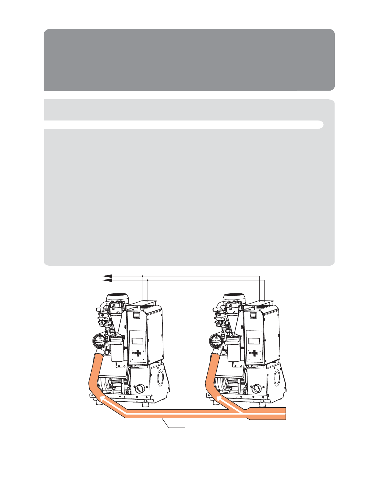
EN 61008-1 are present. Light coloured, wooden, linoleum,
rubber or marble oors can change colour or get marked if
they are kept in contact with rubber vibration-proof devices
(1). Therefore, it is necessary to use a rubber sheet or some
other suitable material to isolate vibration-proof devices
from the oor.
HANDLE
WITH CARE
WARNING
WARNING
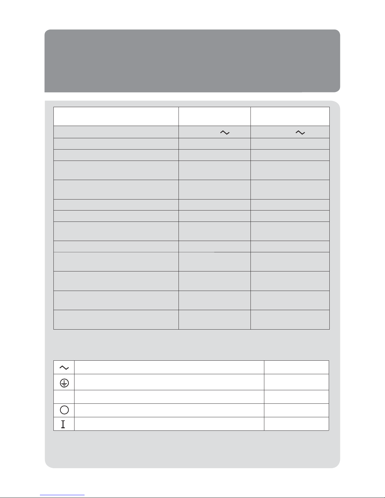
SHOCKWATCH
R
RED INDICATES ROUGH HANDLING
IF RED, NOTE ON BILL OF LADING
INSPECTION MAY BE WARRANTED
MODEL L-55 (37g)
TOLL FREE 1-800-527-9497
www.shockwatch.com
Minima
Maxima
30
20
10
0
10
20
30
40
50
50
40
30
20
10
0
10
20
30
1