CBE PC -200T 4 t IH User manual

PC-200T 4t IH / DS-520AN
23/06/05000291.00
BEDIENUNGSANLEITUNG 3
D
istruzioni d'uso 33
I
Mode d’emploi 23
F
INSTRUCTIONS MANUAL 13
GB

13
MAIN PARTS OF THE ELECTRICAL SYSTEM
GB
u
u
u
u
u
u
u
u
u
u
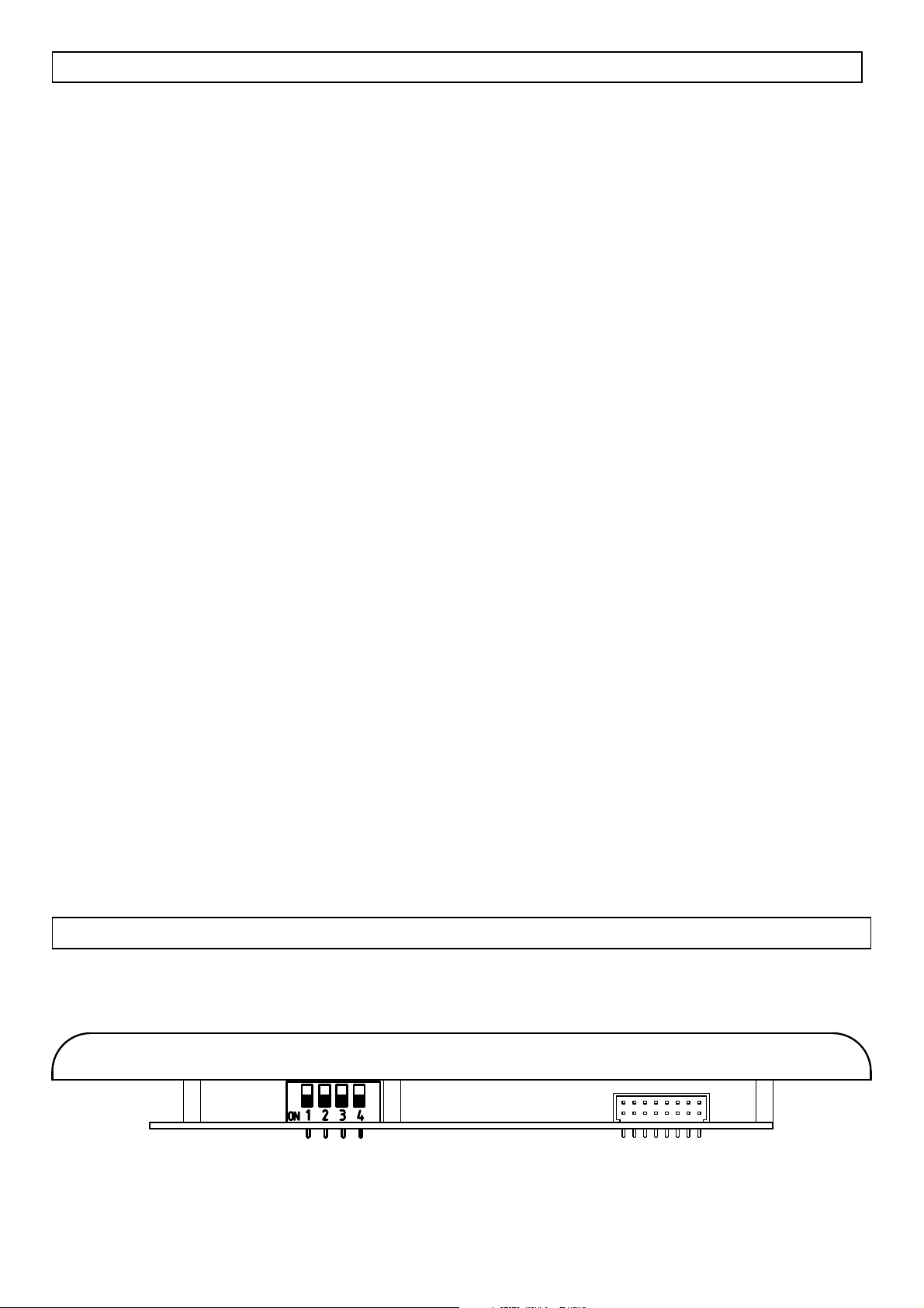
CONTROL PANEL - “PC-200T 4t IH” mains’ control, battery test, tank test, temperature test and clock function.
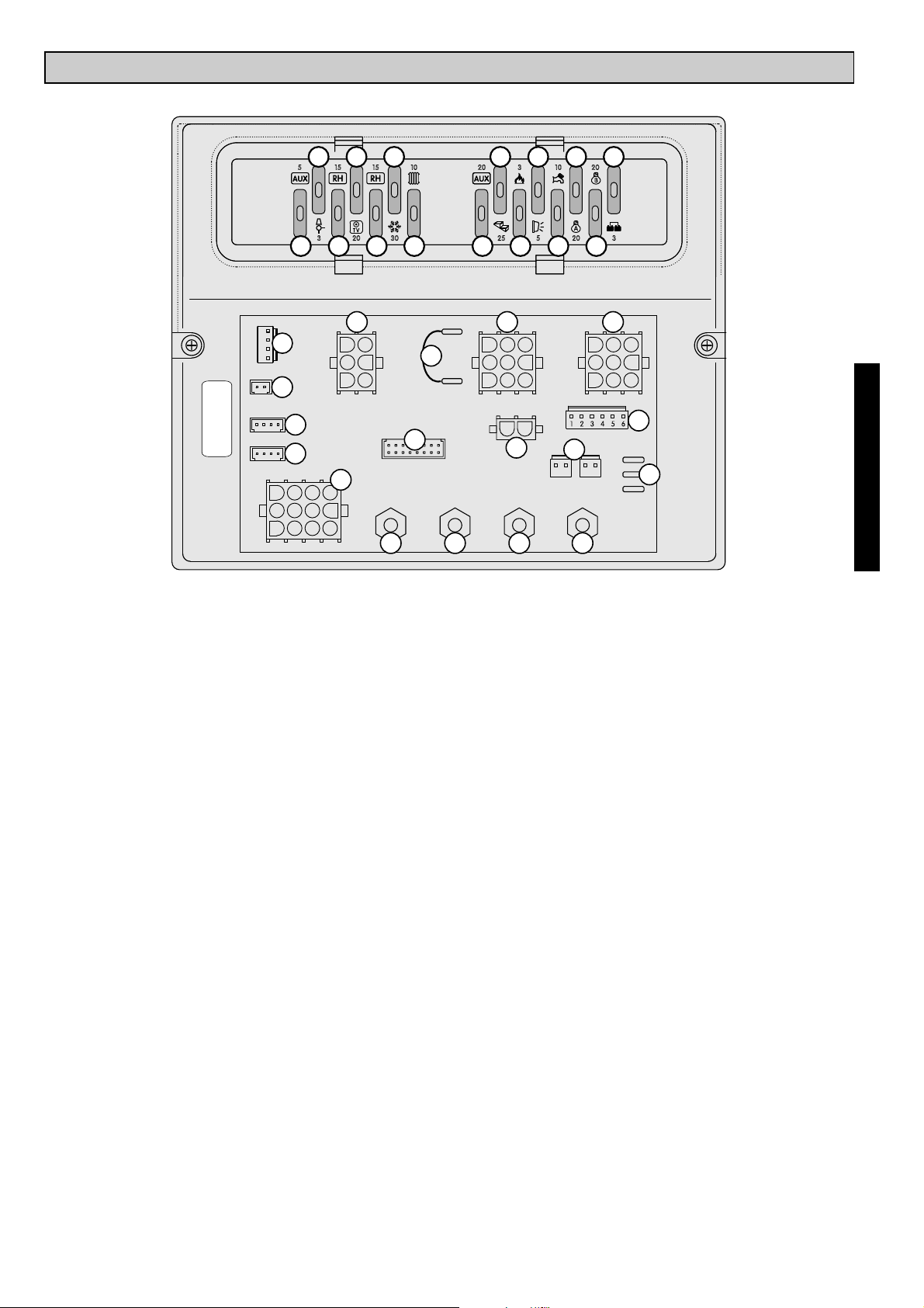
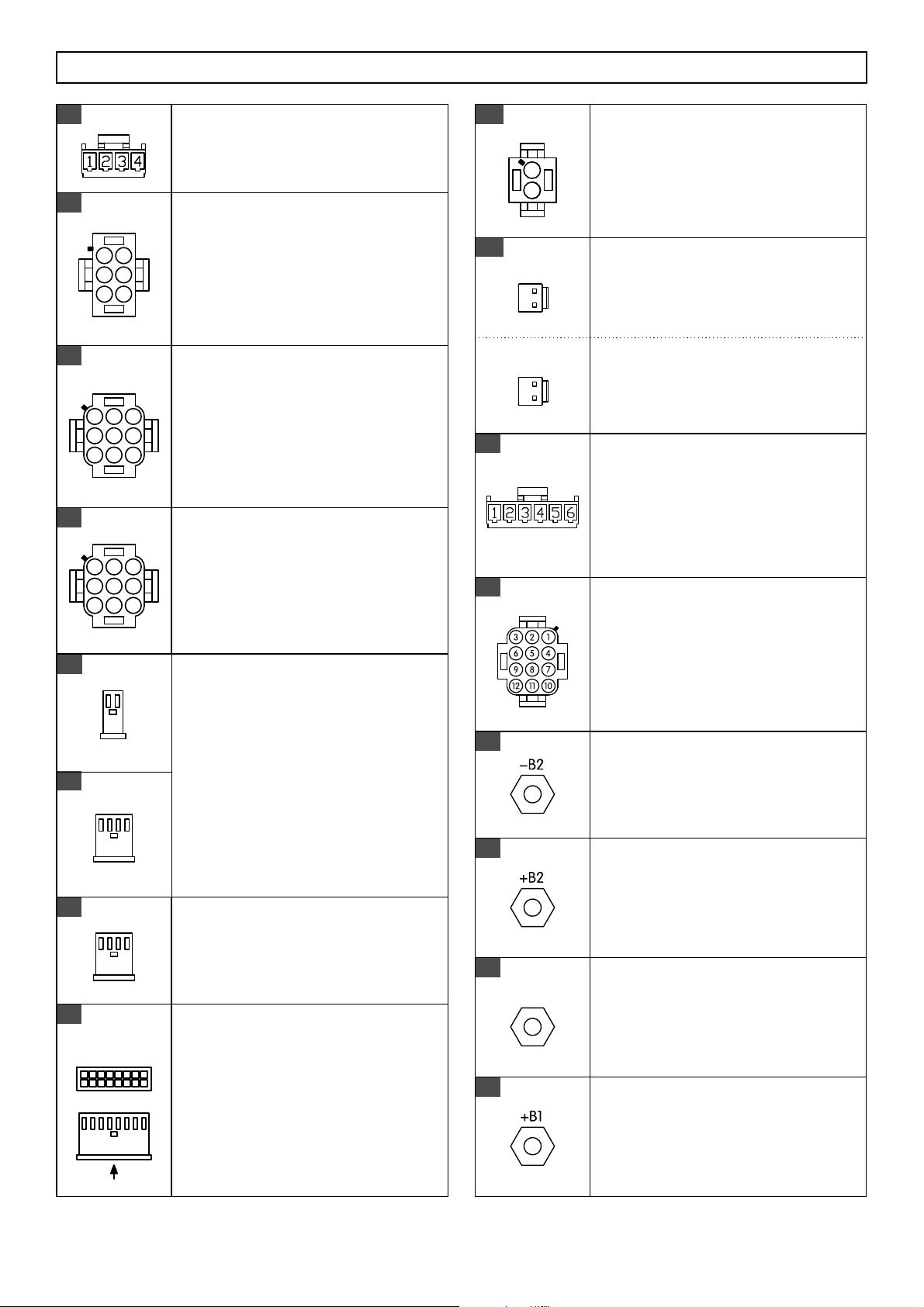
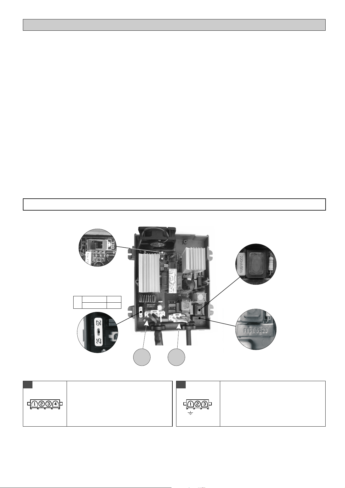
12V DISTRIBUTION BOX “DS-520AN - main relais, battery parallel relais (12V - 70A), fridge relais, pump relais, car
battery recharging device, amperemeter, protection fuses.
LEISURE BATTERY “B2” - it gives power to all the users
CAR BATTERY “B1”
230V CUT-OUT board - it powers and protects all the 230V users
“
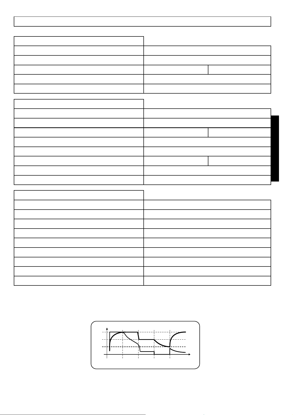
BATTERY CHARGER - buffer-system battery charger.
ELECTRONIC TANK PROBE - it measures the content of the water tanks, visualization in “%”.
TANK PROBE WITH SCREWS “SS/P” - signalization of full waste water tank
ENGINE ALTERNATOR - it recharges in parallel both the car and the leisure battery
“50A”CAR (B1) AND LEISURE (B2) BATTERY PROTECTION FUSES
IMPORTANT
BATTERIES
BATTERY CHARGER
TANK PROBES
FUSES
w
w
w
w
w
w
w
w
Maintenance interventions on the electric plant shall be carried out by specialized personnel.
Before carrying out maintenances works disconnect the battery and the power supply line.
The acid kept in the batteries is poisoning and corrosive. Avoid any contact with skin and eyes.
If the battery is completely discharged it needs recharging for almost 10 hours. If discharged for more
than 8 weeks it may be damaged.
Check periodically the level of the liquid of the battery (with acid); the GEL battery does not need any
maintenance but a countinuous recharging.
In case of a longer stop the services battery has to be connected or recharged regularly.
The battery charger must be installed in a dry and ventilated place.
This device shall be installed by specialized technicians only.
In the event of battery charger’s misuse, the guarantee shall no longer be valid and the manufacturer
declines all responsibility for damages to people and things.
Do not carry out any maintenance when the battery charger is connected to the 230V power supply
net.
Do not cover air intakes and assure an appropriate ventilation.
Before disconnecting the battery charger from 230V power supply, turn the safety switch off.
Replace the fuses only after finding out the real cause of the damage only.
If the fuses are replaced observe the value of the amperage established.
w
w
w
w
w
w
w
w
w
w
Check the correct tightening of the connection binding screw and brush off the oxyde.
If the leisure battery is removed, isolate the positive pole (in order to avoid short-circuits during an
accidental car engine starting).
Never let water in the tanks for long time, in order to avoid foulings, especially in the waste water tank.
230V CUT-OUT BOX
w
w
w
w
w
Before taking away the cover, check if the 230V socket is disconnected.
In order to avoid any damage to the box, check the correct tightening of the connections.
In order to cut power to the whole 230V system, please take care that the 230V main switch must be
on the “0” (OFF) position.
Connect and disconnect the external 230V net only when the main switch is off.
In case of automatic switch break, find the damage before giving power again to the electrical
system.
Read with care the maintenance and use instructions provided by the manufacturer.
ADVICE AND CHECKS
ENGLISH

14
CONTROL PANEL “PC-200T 4t IH”
1)
3)
4)
5)
6)
7)
9)
10)
11)
12)
13)
14)
15)
16)
17)
Test button to check the level in % of the drink and waste water tank
Water pump switch.
Test button to check both internal and external temperature and to set the clock.
Test button to check the voltage of the leisure battery (B2) and car battery (B1), to check charge
and discharge currents of leisure battery and to set the clock.
and to set the clock.
Auxiliary output switch.
Main switch (see minimum voltage control).
Digital display of the clock and of the required test
2)
8)
18)
Lights main switch.
It shows the starting up of the battery parallel when the engine is started.
It shows the car (B1) battery test, the blinking means run-down battery alarm.
It shows the leisure (B2) battery test, the blinking means run-down battery alarm.
It shows the batteries recharging through engine alternator.
It shows the test or alarm of batteries together with the symbols 10 or 11.
It shows the connection to the 230V net.
It shows that the minimal voltage device has switched on.
It shows the drink water tank test, the blinking means empty tank alarm.
It shows the waste water tank test, the blinking means full waste water tank alarm.
It shows the unit of measure: U=Volt, A=Ampere, °C and temperature reference I=internal
temperature, E=external temperature.
CAPTIONS
NOTE: The watch is supplied from the leisure battery (B2).
Should B2 be disconnected, the watch is able to keep working, without visualization, for about
2 weeks.
P C - 2 0 0
%
G
AUX
MOTOR
CAMPERS
G
%
1
2
3
17161513
12
11
10
98 14 18
6
5
4
7

15
FUNCTIONS
MINIMAL VOLTAGE CONTROL
AMPEREMETER
DRINK WATER TANK REFILLING
ELECTRONIC TANKPROBE
An electronic device switches all the 12V mains off, when the leisure battery reaches the minimal
voltage level of 10V. It is possible to switch on again all the mains for about 1 minute by switching
off and then on again the main switch.
They are also automatically switched on again when the voltage is > 12V.
The fridge, the electrical step and the mains powered directly from B2 are excluded from this
device.
The amperemeter is inside the DS-520AN module.
- It measures the current of the leisure battery, users’ consumption and recharge through battery
charger, engine alternator and solar panels.
- Measure range is: -40A ÷ +40A.
- Measure is carried out as difference between charging and discharging currents: a positive value
indicates a charging current, a negative value indicates a discharging current.
To measure the charging of a sole source (battery charger, alternator or solar panels), turn off all
users and other recharging sources.
To measure the consumption of a sole user, disconnect all recharging sources and all
uninterested users.
This function is used during the drink water tank refilling and it shows the level reached by the
water.
You switch on this function by visualizing the drink water tank and by keeping pushed the tank
switch for more than 3 seconds.
When this function is on, you see getting lightened, in sequence, the horizontal segments of the
number ref. 18 and the panel emits sounds in order to warn that the tank is getting filled:
1 short sound at 75%, 2 short sounds at 85% and 1 long sound at 95%.
The electronic tankprobe mod. “SPE” is a capacitive tankprobe. It is powered with 5V and a back-
signal from 0 to 2,5V.
Each 8 seconds the microprocessor gives power to the tankprobe; it is also powered each time you
pust the tank-test button. This was studied in order to avoid useless consumption.
The tank probe has been already programmed by CBE, but it is still possible to check the correct
working of the tankprobe and its setting by following these instructions:
- activate the function
- in this way the tankprobe gets a continue power supply of 5V, so that you can control with a
voltmeter the back-signal of 2,5V and you can also adjust, by using the tankprobe’s trimmer,
possible small variations. (e.g.: value “0 V” = 0 %, value “2,5 V” = 100 %).
- switch the main switch off and then on again.
“DRINK WATER TANK REFILLING”
For this test the tank must be full.Attention:
ENGLISH

16
TEMPERATURE
CLOCK
SETUP
- Internal and external temperatures are measured through sensors which are placed inside and
outside of the vehicle.
- The measuring precision is ± 1°C.
When the panel is switched on, the time gets displayed; after every test-function the time gets
displayed again.
In order to set the clock, keep pushing for 2 secs the test button ref. 1 while the time gets displayed.
The hours’ digits start blinking and by pushing the test buttons ref. 2 e ref. 3 they can be modified
By pushing the test button ref. 1 again, it is possible to start setting the minutes’ digits.
By pushing the test button ref. 1 for the third time, the clock setting is confirmed.
To enter the programmation menu turn on the control panel with the switch ref. 5 while keeping
pushed the buttons ref. 2 and 3.
The progammation is sequential: to shift to the next parameter push the button ref. 1.
1. Voltmeter B1. With the buttons ref. 2 and 3 one can modify the displayed value in 0,2V steps
2. Voltmeter B2. With the buttons ref. 2 and 3 one can modify the displayed value in 0,1V steps
3. Amperemeter B2. With the buttons ref. 2 and 3 one can modify the displayed value in 0,5A steps
4. Internal temperature. With the buttons ref. 2 and 3 one can modify the displayed value in 0,5°C
steps
5. External temperature. With the buttons ref. 2 and 3 one can modify the displayed value in 0,5°C
steps
Pushing again the button ref. 1 you exit the programmation menu.
.
FUNCTIONS
TANKS SETTING
NB: do not modify the dip-switches’ position of the picture.

17
1)
10)
11)
12)
13)
14)
15)
16)
17)
5A fuse to give power the AUX auxiliary exit, it depends on the AUX switch of the control panel "PC-
200 4t AN".
3A fuse for the gas pump supply which depends on the general switch.
auxiliary exit it depends on the main switch.
, it depends on the main switch.
15A fuse to give power to the RH auxiliary exit, it depends on the main switch.
10A fuse to give power to the heating / boiler, it depends on the main switch.
.
3A fuse to give power to spark ignitions (fridge, oven) and gas valve, it is connected directly to the
leisure battery (B2).
5A fuse to give power to the awning light, it depends on the main switch and turns automatically off
when engine is on.
10A fuse to give power to the water pump, it depends on the pump switch.
20A fuse to give power to lights group “A”, it depends on lights main switch.
20A fuse to give power to lights group “B”, it depends on lights main switch.
3A fuse to protect the OUT D+ simulated exit.
AES fridge connection; It is a bridge, which excludes the 3 way function fridge and is used to
connect the AES fridge directly to the B2.
Output + for the control of the auxiliary relais (e.g. motorized step, AES fridge, electric water
discharge valve, electric antenna motor, etc.) which works only when the engine is started.
2)
3)
4)
5)
15A fuse to give power to the RH ,
20A fuse to give power to TV sockets
6)
7)
8)
9)
30A fuse to give power to 12V AES and 3-way fridge. The 3-way fridge turns off automatically when
engine is off.
20A fuse to give power to the AUX direct exit (f.e.: solar regulator), it is connected directly to the
leisure battery (B2)
25A fuse to give power to the motorized step, it is connected directly to the leisure battery (B2).
DISTRIBUTION BOX “DS-520AN”
1 2 1 2
3 20 30
5 1015 15
25 5 20 3
20 3 10 20
A
B
8
9
1 10
2 11
3 125 147
4 136 15
-B2 +B2 + OUT 12V
1 2 3 4
1 2 3 4
1
4
7
10
2
5
8
11
3
6
9
12
1
9
8
16
1
4
2
5
3
6
1
4
7
2
5
8
3
6
9
28
20 21
16
19
24 25
31
30
29
+B1
32
RH RH
AUX
17
1
2
26A 26B
27
1
4
7
2
5
8
3
6
9
AUX
22
12
23
1
4
3
2
18
RE-VI
RE-EL
POT
ENGLISH

CONNECTIONS
18
AWNING LIGHT
CONTROL PANEL
MAINS
USERS
USERS
DRINK WATER TANK
27
25
19
21
20
24
BLACK
WHITE
WHITE
RED
WHITE
BLACK
1
9
VISTO DA "A"
A
8
16
MASSE
28 WHITE
123 4
14
25
36
147
258
369
147
258
369
LEISURE BATTERY
EXIT 12V
CAR BATTERY
MASSE
30
31
31
29
+ OUT 12V
WHITE
18
20B
2
1
WHITE
2
1
RED
SIGNALS (OPTION "B")
26B
1
2
SIGNALS (OPTION "A")
26A WHITE
32
1) + exit RH
2) + exit gas valve
3) + exit AUX switch
4-5) + exit TV sockets
6) + exit RH
1) + exit AUX direct B2
2-3) + exit 3-way fridge / AES
4) + exit motorized step
5-6-8-9) + exit gas ignition
(fridge, kitchen, boiler’s
valve, etc.)
1) + exit Truma C
2) + exit water pump
3) + exit awning light
4-5-6) + exit lights group "A"
7-8-9) + exit lights group "B”
To connect to the drink water
electronic probe.
To connect to the 16 poles
connector of the control panel.
1) + input signal contact key
engine starting.
2) + input signal “S” net coming
from the CBE battery charger
1) N.C.
2) + input signal contact key
engine starting.
1) + input signal “S” net coming
from the CBE battery charger
2) N.C.
1) masse
2) + exit awning light direct B2
3) + exit awning light
4-5-6) OUT D+
To connect to the mains' masses.
To connect to the negative pole of
the services battery or to the
chassis of the vehicle.
To connect to the positive pole of
the leisure battery.
To connect to the positive pole
(battery charger, solar regulator).
To connect to the positive pole of
the car battery.
NOT CONNECTED
23 BLACK
123 4
ELECTRONIC WASTE WATER TANK
PROBE (RE-EL)
WASTE WATER TANK PROBE WITH
SCREWS (RE-VI)
22 BLACK
To connect to the waste water
tank probe with screws or to the
electronic waste water tank probe.
NB: Don't connect both tank
probes!
12

CAR BATTERY (B1) RECHARGING
LEISURE BATTERY (B2) RECHARGING
ELECTRONIC BATTERY SEPARATOR
BROKEN FUSE ALARM
When the battery charger is charging, an electronic device allows a recharging (max 2A) of the car
battery (B1), the system gives priority to the leisure battery (B2).
by alternator: through the separating relais, when the engine is started. The engine ignition
controls electronically a small relais which controls the other relais: parallel, fridge, awning light, etc.
by 230V net: buffer system through battery charger (see " ").
by solar panel: through a solar regulator.
An electronic device, which is controlled by the engine ignition, switches on the battery parallel
when the alternator voltage is over 13.3V and switches it off when the engine ignition is off or the
voltage is under 12V. The device is not working when the 230V net is connected.
This device controls also the external light’s relais, which works only when the engine is off.
Under each fuse is positioned a red LED.
The lighting of the LED signals that the fuse is broken and it is necessary to replace it with another
fuse with the same value. The alarm is activated only when the control panel is on and the user
related to the fuse is switched on.
NOTE: before replacing the fuse find out the problem that determined the intervention of the
protection and fix it, necessary with the help of specialized technicians.
a)
b)
c)
battery charger
FUNCTIONS
19
ENGLISH

20
SWITCH MODE BATTERY CHARGER “CB 510/516”
The CB 510/516 switch-mode battery charger has been expressly designed for the caravanning and
boating sector and can automatically charge 12Vd.c. lead batteries.
1) with maximum current until the end-charge voltage is reached:
The battery charger is protected against overtemperature and the 12Vd.c. outputs are protected against
short circuit and polarity inversion.
The charging system is carried out in 4 stages:
2) when the threshold is reached the charger continues to operate for 90 minutes (lead
batteries) or 8 hours (gel batteries) with constant voltage.
3) voltage holding 13.8Vd.c.(gel batteries) or 13.5Vd.c. (lead batteries)
4) After 10 hours, the battery charger reaches the mode and begins to operate again only
when the battery voltage is lower than 13Vd.c.
The high frequency switching technology allows to have high performances with small dimensions and
limited weight.
battery charging
Note: the end-charge voltage is reached only if the battery is efficient.
end-charge
Constant
stand-by
CONNECTIONS
12
Pb / Gel
Battery 230Va.c. On/Off
Fuse 230Va.c.
F2 - 2A
15A
25A
F1
CB 510
CB 516
S-
+
1) + 12Vd.c. supply
2) - 12Vd.c. supply
3) N.C.
4) Net signal (+12Vd.c.)
1) Masse
2) Neutral
3) Line
N L
- Technical data are indicated also in the label inside the cover -
12Vd.c. CONNECTION
1WHITE 230Va.c. CONNECTION
2WHITE

21
SPECIFICATIONS
INPUT TECHNICAL DATA
Nominal voltage
Frequency
230Va.c. 10%±
50 Hz
Maximum power
Protection fuse ref. F2
Security switch
2A (glass 5x20)
230Va.c. luminous
CB516 - 250 WCB510 - 150 W
OUTPUT TECHNICAL DATA
Maximum voltage 14,3 Vd.c. (Pb-Gel) - 14,1Vd.c. (Pb-Acido)
Maintenance voltage
Maximum output current
Charge line IUoU
13,8 Vd.c. (Pb-Gel) - 13,5Vd.c. (Pb-Acido)
CB516 - 16ACB510 - 10A
Short circuit and inversion polarity protected ref. F1
Thermal protection Yes
Battery type selector Pb-Acido / Pb-Gel
CB516 - 25A )(car typeCB510 - 15A )(car type
Net presence signalling (S) 12Vd.c. ; 50 mA
GENERAL TECHNICAL DATA
Efficiency 86 %
Room temperature
Ventilation
0 - +50 °C
Automatic regulation variable (only CB-516)
Net connection
Security directives
EMC directives
“mate-n-lock" 3 poles
73/23/CE, 93/68/CE
89/336/CE, 92/31/CE, 93/68/CE
Battery connection
Dimensions
“ 4 polesmate-n-lock"
180 x 140 x 85 (mm)
Weight 1kg
CHARGING LINE “IUoU”
V = Volt A = Ampere C = Carico - Load
VI
V I
C
t
I Uo U ST-BY Uo
ENGLISH

22
180
140
85
Fig.1 - DIMENSIONS (mm):
INSTALLATION
110
Fig.2 - VERTICAL INSTALLATION
110
197
157
IMPORTANT: - The installation of this device must be carried out by specialized technicians.
- Do not carry out any maintenance when the battery charger is connected to the
230Va.c. power supply net.
-
- Caution, do not connect the battery charger:
when a generator set with non stabilised output voltage is employed
with power mains voltage exceeding the rated value (230Va.c. ±10%)
- In case of battery charger’s misuse, the guarantee falls off and the manufacturer
declines all responsibility for damages to people and things.
1
1
BATTERY CHARGER
CABLES
- Use cables with appropriate section, minimum cross section area 4 mm².
- Protect cables from any possible damage.
- Install the battery charger in an appropriate housing, dry and ventilated; maximum efficiency can be
obtained when the battery charger is installed in vertical position (see figure 2), keeping the front side
at minimum distance of 300 mm and the bottom and top side at a minimum distance of 100 mm from
the housing sides.
- Do not cover air intakes.
- To guarantee a proper change of air the installation of two air intakes (one placed on the top and one
on the bottom, see figure 2) ensuring a working temperature inside the housing not exceeding
40 - + 50 °C.
- Make sure that the 230Va.c. safety switch can be easily reached.
- The connection to power supply mains shall be made in accordance with national installation rules.
- Before disconnecting the battery charger from 230Va.c. power supply, turn the safety switch off.
- The installation requires the fixing of no. 4 pins that can be easily placed on the 4 sides.
- The battery charger can be installed together with CBE 12V and 230V distribution panels, using the
appropriate modular joints.
BATTERY
- Lead-acid batteries shall be positioned in a well ventilated place.
- Use only 12Vd.c. rechargeable lead batteries (capacity >40Ah).
- Do not use "not rechargeable" batteries.
- Exhausted batteries shall be disposed in accordance with existing environmental protection
regulations.
Warning:

43
B1
50A
+
KEY CONTACT
INT. C°
230V
2x13A 0,03A
SCATOLA
230V
B2
50A
LICHTER A, B, C, D
AUSSEN
INNEN
TRITTSTUFE
GAS PIEZO
HEIZUNG / BOILER
KÜHLSCHRANK
WASSERPUMPE
AUX
AUX
LIGHTS A, B
AWNING LIGHT
STEP
GAS PIEZO
HEATING / BOILER
FRIDGE
PUMP
AUX
EXT. C°
WASTE WATER
TANK
DRINK WATER
TANK (1)

w
w
w
w
I dati riportati nei fogli di istruzioni possono subire modifiche senza preavviso alcuno, questo è dovuto
alle continue migliorie tecniche. I disegni e i testi riprodotti sono proprietà della CBE. E' vietata la
riproduzione integrale o parziale e la comunicazione a terzi senza l'autorizzazione scritta.
Technical data on instructions sheets can be modified without notice, because technical improvements
are continually made. Design and texts are CBE property. Integral or partial reproductions are no
admitted as well as communications to third parties without written permission.
Die in den Gebrauchsanweisungen geführten Daten können ohne Vorankündigung geändert werden, in
Zusammenhang mit den technischen Verbesserungen. Die veröffentlichtenAbbildungen und Texte sind
Eigentum der Fa. CBE. Jegliche Art von Vervielfältigung, komplett oder teilweise, ist ohne schriftliche
Genehmigung untersagt.
Les données reportées dans les pages des instructions peuvent subir des modifications sans aucun
préavis ,ceci en vue des continuelles améliorations techniques. Les dessins et les textes reproduits sont
de propriété de la CBE. La reproduction totale ou partielle et la communication à tiers, sans autorisation
écrite sont interdites.
Spini di Gardolo, 116 - 38014 Gardolo (TN) - Italy
Tel. +39 0461 991598 - Fax +39 0461 960009 - www.cbe.it - cbe@cbe.it
CBE Elettrotecnica
89/336 EMC
73/23 e 93/68 EEC
This manual suits for next models
1
Table of contents
Other CBE Industrial Equipment manuals