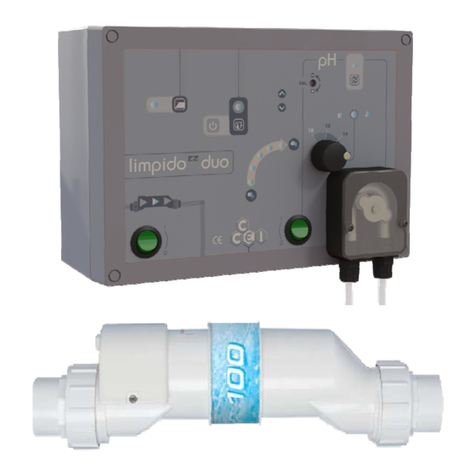
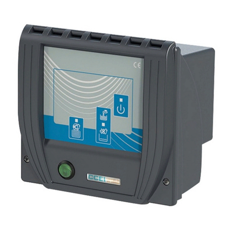
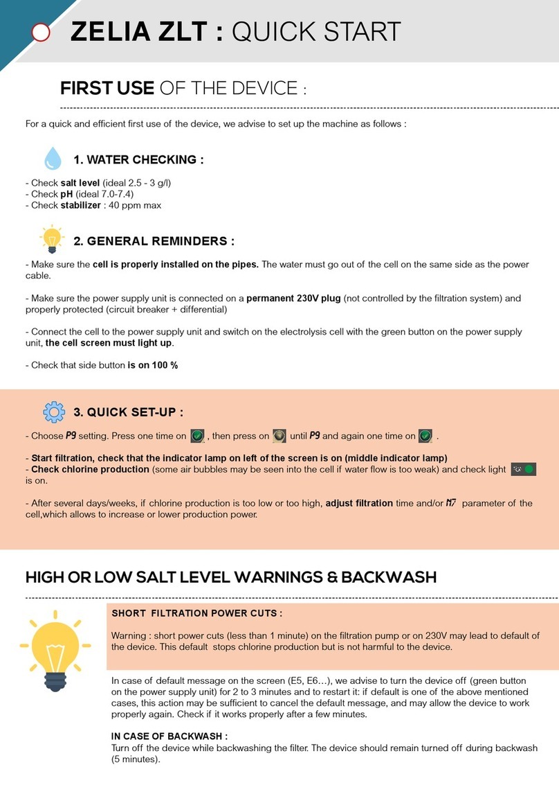
ccei LIMPIDO LTE DUO User manual

Modification
INDICE
DA
TE
LIMPIDO
LTE
DUO
A
02/2007
User manual
V1.0
®
Simply Enjoy Water
W
A
R
N
I
NG
:
READ
CAREFULL
Y
THESE INSTRUCTIONS BEFORE
INSTALLING, PUTTING
INTO
SERVICE
OR USING
THIS DEVICE.
Contents
CARACTERISTICS
----------------------------------------------------------------------------------------------------------------------------------------------------------
2
PRESENT
ATION
---------------------------------------------------------------------------------------------------------------------------------------------------------------------
2
Salt electrolysis
. . . .
. . . . . . . . . . . . . . . . . . . . . . . . . . . . . . . . . . . . . . . . . . . .
. 2
pH regulation . .. . . . . . . . . . . . . . . . . . . . . . . . . . . . . . . . . . . . . . . . . . . . . .
. 2
DESCRIPTION OF EQUIPMENT
-----------------------------------------------------------------------------------------3
Electrolysis cell .
. . . . . . .
. . . . . . . . . . . . . . . . . . . . . . . . . . . . . . . . . . . . . . . . . .
.3
Circulation detector (Flow-switch) . . . . . . . . . . . . . . . . . . . . . . . . . . . . . . . . . . . . .
.3
pH probe. . . . . . . . . . . . . . . . . . . . . . . . . . . . . . . . . . . . . . . . . . . . . . . . . . . . . . .
.3
OPERATION
-------------------
----------------------------------------------------------------------------------------------------------------------------------------------------------
3
Electolyse . . . . . . . . . . . . . . . . . . . . . . . . . . . . . . . . . . . . . . . . . . . . . . . . . . . .
.3
Display . . . . . . . . . . . . . . . . . . . . . . . . . . . . . . . . . . . . . . . . . . . . . . . . . . . . . .
.4
P
roduction indicator . . .
. . . . . . . . . . . . . . . . . . . . . . . . . . . . . . . . . . . . . . . . .
.4
Checking salt level . . . . . . . . . . . . . . . . . . . . . . . . . . . . . . . . . . . . . . . . . . . . . . . .
.4
pH regulation . . . . . . . . . . . . . . . . . . . . . . . . . . . . . . . . . . . . . . . . . . . . . . . . . .
.5
INST
ALLA
TION
-----------------------------------------------------------------------------------------------------------------------------------------------------------------------
5
hydraulic
installation. . . . . . . . . . . . . . . . . . . . . . . . . . . . . . . . . . . . . . . . . . . . . . . .
.5
Electrical installation. . .
. . . . . . . . . . . . . . . . . . . . . . . . . . . . . . . . . . . . . . . . . . .
. .6
pH probe installation. . . . . . . . . . . . . . . . . . . . . . . . . . . . . . . . . . . . . . . . . . . . . . . . .
.6
S T A RT U P ----------------
----------------------------------------------------------------------------------------------------------------------------------------------------------------
7
Adjusting the production level
. . . . .
. . . . . . . . . . . . . . . . . . . . . . . . . . . . . . . . . . . .
.7
Stabiliser .
. . . . . . . . . . . . . . . . . . . . . . . . . . . . . . . . . . . . . . . . . . . . . . . . . . . . .
.7
pH control. . . . . . . . . . . . . . . . . . . . . . . . . . . . . . . . . . . . . . . . . . . . . . . . . . . . . . .
.7
MAINTENANCE
--------------------------------------------------------------------------------------------------------------------------------------------------------------------
7
Calibration
. . . . . . . . . . . . . . . . . . . . . . . . . . . . . . . . . . . . . . . . . . . . . . . . . . . . .
.7
Wintering .
. . . . . . . . . . . . . . . . . . . . . . . . . . . . . . . . . . . . . . . . . . . . . . . . . . . . .
.7
Adding salt . . . . . . . . . . . . . . . . . . . . . . . . . . . . . . . . . . . . . . . . . . . . . . . . . . . . . .
.8

CARACTERISTICS
General
Dimensions
(lxhxp) . . . . . . . . .
.
265x390x140
Weight . . . . . . . . . . . . . . . . . . . . . . . . . . .6 kg
1- phase power voltage. . . . . . . .
.230V/50Hz
Protection index . . . . . . . . . . . . . . . IP-55
Insulation .
. . . . . . . . . . . . . . . . . . . . .
Classe
II
Supplied Accesories
pH probe –
Calibration solution
pH7
Reduction
63-50
(x2)
Flow switch integrated
User manual
Electrolysis
Chlorine production
. . . . . . . . . . . . . .30
g/h
Pool volume maximum
. . . . . . . . . . . 40 à 80m3
Cell self cleaning
. . . . .
. Polarity
inversion
Power consumption
. . . . . . . . . . . . .100W
Salt level . . . . . . . . . . . . . . . . . . .2,5g to
5g/l
M
ax. pressure in the cell . . . . . . . . . . . . .3
bar
Max. flow in the
cell
. . . . . . . . .
.22m
3
/h
Electrodes
. . . . . . . . . .
. Solid titanium plates
Ruthnium coating
pH measurement
Measurement range . . . . . . . . . . . . de 7 à
7.6
Regulation range . . . . . . . . . . de 7 à
7.6
Precision . . . . . . . . . . . . . . . . . . . . . . . .
.0,2
Peristaltic pump
Max. flow . . . . . . . . . .. . . . . . . . . . . . .1,8
l/h
« On/off »-dosing
Regulation mode . . . . . . . . . . . . . . . . .pH-
PRESENT
A
T
ION
LIMPIDO
®
LTE
DUO is an automatic water treatment system for swimming pools.
LIMPIDO
®
LTE
DUO combines a sterilising device via salt
water electrolysis and pH regulation which together help together the pool water hygienic and clear
.
LIMPIDO
®
LTE
DUO is easy to install and to use. Nevertheless we recommend to readu carefully this manual before installing the device.
SALT ELETROLYSIS
Salt water electrolysis separates the salt (NaCl) into sodium (Na) and Chlorine (Cl). The latter is dissolved immediately in the water, producing
hypochlorous acid (HClO). This powerful disinfectant destroys bacteria and algae before it is converted back into salt.
The quantity of chlorine required to disinfect a swimming pool increases with the temperature and pH (alkalinity) of the water.
For the safety of the equipment, the electrolyser only produces chlorine when the flow-switch signals the circulation of water in the cell. The
electrolyser only produces chlorine, therefore, during the filtration periods determined by the programming timer on the swimming pool’s
electrical box. During these filtration periods, the production time comprises cycles of two periods (Normal and Inverse) which alternate the
polarity of the electrodes. This polarity inversion prevents the electrodes from scaling. The duration of each production cycle is 4 hours and is
broken down as per the table opposite:
:
P
HASE
1
P
HASE
2
P
HASE
3
P
HASE
4
Production
+
Wait
Production
+
Wait
Production
-
P
roduction cycle
=
4h
PHASE
1, normal production :
[1h00].
PHASE
2, rest :
[1h00].
PHASE
3, inverse production mode :
[1h00].
PHASE
4,
rest
:[1h00].
Production
-
At the end of the filtration cycle, the LIMPIDO© LTE DUO stops instantaneously and, when filtration restarts it picks up its cycle at exactly the
same point as when it was interrupted. The main advantage of this mode of operation is the guarantee, in all cases (even if there is a power
failure), of strictly identical normal and inverse production times and, as a consequence, provides the user with optimum descaling of the cell
(guaranteed production quality and a long useful life of the equipment).
PH REGULATION
The pH denotes the hydrogen potential of the water. A pH lower than 7 means that the water is acidic while a pH of more than 7 means that the
water is alkaline. The water is neutral when its pH is equal to 7. It is generally agreed that the perfect pH for a swimming pool is between 7.0 and
7.6. LIMPIDO© LTE DUO keeps the pH of the pool within these limits.
The sodium hypochlorite produced by electrolysis is an alkali which increases the water's pH.
LIMPIDO LTE DUO measures the pH using an amperometric sensor and, depending on the results of the measurement, activates a dosing pump
to correct the pH by adding an acid solution (pH-).
Really easy to use, LIMPIDO LTE DUO has 4 predetermined setpoint : 7 / 7,2 / 7,4 / 7,6. The user must calibrate the probe during the initial
operation of the device (see. Operation ).
CAUTION: The acids used for pH correction are very corrosive and must be handled and stored with the greatest caution!
2
User Manual
LIMPIDO
LTE
DUO
V1.0

3
User manual
LIMPIDO
LTE
DUO
V1.0
DESCRIPTION OF THE
EQUIPMENT
ELECTROLYSIS CELL
This is an essential component of the LIMPIDO LTE DUO must be
handled with due care. The cell is fitted with eletrodes made of full
titanium plates treated with reatunium oxide
It is specially designed to offer maximum useful life and to reduce
maintenance.
The provided union fittings enable to adapt the cell on a
63mm pipe or 50mm with both pipes saddles
Flow switch
Integrated electrolysis cell
WATER FLOW DETECTOR (FLOW-SWITCH)
The flow-switch, provided with the LIMPIDO LTE DUO prevents the electrolyser from operating if there is no flow or during backwashing. It
prevents the risk of any accumulation of hydrogen or over-heating, thus ensuring the safety of the device.
PH probe
The pH probe is comprised of two electrodes which supply a proportional voltage to the water’s pH. The pH sensor is fragile and must be
handled with care. It is essential to keep it immersed in an aqueous solution.
INSTALLATION
production
indicator
Electrolysis control
pH probe
pH setting button
Metearing pump
Suction strainer injection
pipe
On/Off
Electrolysis
switch
SENS
OF
§CIRCULA
T
IO
N
ELECTROL
YSIS
The system is switched on using the light on the front.
Two buttons are used to adjust the LIMPIDO LTE DUO operating conditions
.
■
Production setting
This button is used to adjust the intensity of production in order to offset the variations in the water’s conductivity.
The button must be set to the position for maintaining the level of production in the green zone (see Production indicator).
■
Recommended
pH setting
This button is used to set the recommanded pH value
.

User Manual
LIMPIDO
LTE
DUO
V1.0
Light
Color
Status Signification
Circulation
Green
Flashing
Detected flow, cycle in run
OPERATION
DISPLAY
Polarity indicator
P
roduction light
The system’s statu scan be viewed via the pilot lights ‘LEDS):
Off Production cycle stop
Polarity Green On/Off shows the polarity for the current production cycle
.
Production
Light Red On/Active Overproduction fault: Too much salt (1)
Light Yellow On /Active High production (2)
Light Greeen On /Active Optimum production conditions (3)
Light Yellow On /Active Low production (4)
Light Red On /Active Under-production fault: lack of salt (5)
PRODUCTION INDICATOR
The
production indicator is used to monitor the production level.
The
production
level
depends on the position of the production adjustment
knob
and the salt level.
To
protect the cell, production should be kept within the green
zone.
The production level is indicated by the last indicator light from the bottom.
If
the yellow and the first green indicator light are on, this
means
that production is
optimal
When only the yellow indicator light is on, the production level should be increased one notch via the production adjustment knob.
If
no
green
indicator light is on, despite maximum adjusted production, the salt level must be
checked.
When the top yellow light is on, production should be
decreased.
LIMPIDO
®
-L
TE
is equipped with a protection device that stops production whenever a production fault is
detected
Over
production fault
This
fault usually occurs if there is too much salt in the
pool.
The device cuts production whenever a fault is detected, to prevent
an
excess of current which may
damage
the cell and control
relays.
This
fault most often occurs just when salt is being
added
into the
pool
and
LIMPIDO®
is started up before the complete dilution of the
salt.
If
the fault persists, check the salt level.
If
over 5 h/l, drain the water
and
fill
the pool until a salt level of less than or equal to 5 g/l is
obtained
Underproduction fault
LIMPIDO®
comes equipped with a detection device that
stops
treatment when there is
insufficient
salt during
operating.
In the case of an underproduction fault, add salt and wait until it has
completely dissolved before starting up production
again
.
Water conductivity decreases with the temperature, chlorine production decreases when the water cools.
This
phenomenon is beneficial for
limiting production during winter when the quantity of chlorine necessary for disinfecting is very low. An underproduction fault is likely to
occur when there is a drop in water temperature. The user thus has the choice of stopping treatment during winter or to compensate
by
additional
salt
TO
ELIMINATE
A
PRODUCTION
F
AUL
T
,
THE
APP
ARA
T
US
SHOULD BE TURNED
OFF,
THEN
ON AGAIN
.
CHECKING
THE SALT LEVEL
The salt level in the pool must not drop below 3g/l. It is recommended to keep the salt level between 3.5g/l and 4.5g/l to protect the
electrolysis cell.
To control precisely the salt level of your pool, we recommend to use a conductivity tester (ref. T-SEL sold separately). This easy-to-use
instrument allows the salt level to be directly read in g/l. In addition, there are test strips used to control efficiently the salinity of your
water. The production indicator provides you with an estimation of the salt level: place the adjustment knob on the min. position and make
sure the display is in the green zone. If the measured value is outside the normal range, refer to the maintenance chapter.
4
Water flow in cell
1

User Manual
LIMPIDO
LTE
DUO
V1.0
LIMPIDO
®
LTE
DUO
OPERATION
PH REGULA
T
ION
Calibration screw
LEFT PILOT LIGHT
Left light
:
THE PUMP
DOESN’T
NOT RUN
Right light
:
THE PUMP RUNS
Every two minuts
Central light
:
THE PUMP
DOESN’T RUN.
When the left-hand pilot light is on, this means that the water’s pH is below the recommended value
:
THE PUMP DOESN’T RUN
.
This indicator lights rarely on, as for example during the start up or during few seconds when the filtering pump starts to run.. During normal
operating, if this LED is often on, it is recommended to measure the water pH and to get in touch with your dealer.
CENTRAL PILOT LIGHT
When the central pilot light is on, this means that the water’s pH is equal to the recommended value
:
THE PUMP DOESN’T RUN
.
RIGHT PILOT LIGHT
When the right-hand pilot light is on, this means that the pH is above the recommended value
:
THE PUMP RUN
.
INST
ALLA
TION
HYDRAULIC
INST
ALLA
TION
CAUTION
: In order to work perfectly the water should flow in the cell from the left to the
right
.
The bypass installation is
necessar
y
,
when the inline flow exceeds
22m
3
/h
(see
below)
Installation
SIDE VUE
tank
pH-
from
FIL
TER
and heater equipment
Installation
TOP VUE
LIMPIDO
®
LTE
DUO
To the
pool
Output
Intake
NOTE : The
LIMPIDO
®
-L
TE
DUO should be
installed
after a heater
5

User manual
LIMPIDO
LTE
DUO
V1.0
INSTALLATION (Contd.)
ELECTRICAL INSTALLATION
Connect the equipment to a 230V/50Hz socket which is protected by a 30mA differential device in accordance with Standard NF C15-100.
If necessary don’t hesitate to contact a professional.
IMPORTANT : Do not disassemble the unit.
pH PROBE INSTALLATION
The sensor is used to measure and monitor the swimming pool’s pH by sending
a signal to the electrical box.
This sensor is fragile and must be handled with care. The end of the sensor must
always be immersed. It is therefore delivered with a hood filled with liquid
which should only be removed just before installing in the piping system
.
pH sensor
Connect the BNC connector
The sensor must be positioned so that its end part is in the middle of the
piping system. It is essential to ensure that the piping system used to install the Place the probe on the probe supp.
sensor is always filled with water. In the event of hibernation, the sensor Use
TEFLON
to screw this part to
must be removed and put back with its end in the hood filled with water. the pipe saddle
Pipe saddle to be positioned
on the piping system
STARTUP
After completing all the hydraulic installation (sensors, gate valves, cell, etc) as per the section on hydraulic installation, follow the steps below
to successfully start up the equipment.
Il est nécessaire d’étalonner périodiquement la sonde de pH afin de vérifier la précision de la mesure et compenser son vieillissement éventuel,
notamment à la mise en service.
Before proceeding with any actual calibration, you should:
➜Set the recommended value to 7.0
➜Stop filtration (LIMPIDO© LTE DUO switches off) 1
➜Remove the sensor from the sensor holder, rinse and dry it.
➜Block the sensor holder (with a 5 euro cent coin)
Calibration is thus done in the following way:
➜Immerse the sensor in the pH7 setting solution 2 3
➜Restart filtration
➜Using a screwdriver, adjust the calibration screw so that the entral pilot ligh :
➜Turn towards minus if the red pilot light on the left is lit
➜Turn towards plus if the red pilot light on the right is lit
➜When the central pilot light is lit, the equipment is calibrated.
➜Stop filtration
➜Put the sensor back in the swimming pool piping system
➜Restart filtration.The calibration process is over.
Important : In order to avoid any errors due to ageing of the sensor, the
calibration must be checked regularly (about once every month).
CHECKING THE SALT LEVEL
LIMPIDO® LTE DUO is designed to work with a water conductivity corresponding to
a salt level between 2g/l and 5g/l at 20°C.
When the salinity level is not right, LIMPIDO® LTE DUO stops the production and the
production lights indicates
“TOO MUCH SALT” : red LED, on top, lights on
“LACK OF SALT” : red LED, down, lights on
When one of these messages appears, check first if the cell is well connected to the
panel control and that it’s in good condition, check then the water salinity and do the
necessary corrections.
The conductivity of water is proportional to the salinity but also depends on the
temperature (2,2%/°C).
At 30°C the salt level max is
5g/l
à
3,9g/l
Lack of salt Too much salt
5°C
10°C
15°C
20°C
25°C
30°C
35°C
40°C
MINI 3,3 3,1
2,8
2,5
2,2 2,0 1,7
1,4
I
DÉAL
4,7 4,3
3,9
3,5
3,1 2,7 2,3
2,0
MAXI 6,7 6,1
5,6
5,0
4,5 3,9 3,4
2,8
salinity
g/l
6
Important : after opening, the calibration solution keeps for a
few months maximum. It must be renewed at least once each
season. If not, the guarantee will not cover its value.

User manual
LIMPIDO
LTE
DUO
V1.0
OPERATION (Contd.)
SETTING THE PRODUCTION LEVEL
The amount of chlorine needed to maintain the quality of a swimming
pool’s water is conditioned by numerous parameters
:
■
Water acidity (pH)
■
Water hardness
(TH)
■
Water temperature
■
Sunshine (UV rays)
■
Stabiliser level (Isocyanuric acid)
■
Volume of pool
In particular, the presence of a stabiliser imposes a free chlorine content
of 2mg/l (2ppm), while 0.4mg/l is sufficient to treat a pool without any
stabiliser. Similarly, the rise in pH (lack of acid), causes a rapid fall in
the amount of active chlorine contained in the water. Thus, when the pH
rises from 7.2 to 8.2, the level of chlorine falls from 70% to 20%.
100
90
80
70
60
50
40
30
20
10
0
5,5 6,0 6,5 7,0 7,5 8,0 8,5 9,0 9,5
ST
ABILISER
Chlorine is gaseous at ambient temperature. Its solid form (briquettes, granules, etc.) is obtained by combining it with a cyanuric acid molecule.
This cyanuric acid plays the role of stabiliser since it protects the chlorine from degradation cause by UV rays from the sun. However, this
cyanuric acid is not consumed and accumulates inexorably in swimming pools treated with chlorine briquettes and ends up inhibiting the potential
of the chlorine. For public pools, the maximum concentration of cyanuric acid is set at 80 ppm (or mg/l).
Treatment by salt electrolysis avoids this overdosing of cyanuric acid, although it is recommended that you add, just once, when filling with water,
between 25 and 50 ppm (or mg/l) of stabiliser. With a high level of sunshine, in fact, 90% of free chlorine is destroyed within two to three hours in
the absence of cyanuric acid, while this proportion is reduced to 15% with 30pmm of stabiliser (cyanuric acid). Salt is available commercially
which is specially adapted for swimming pools and enhanced with an appropriate level of stabiliser.
MONITORING THE pH
In order to make the LIMPIDO® LTE DUO as effective as possible, it is essential to keep the pH of the
water between 7.2 and 7.6. As an indication, the table opposite sets out the running times keep the pH of
the water between 7.2 and 7.6 of the LIMPIDO© LTE DUO, depending on the volume of the pool basin
and the pH value, for water at a temperature of 25°C.
The water temperature varies throughout the season and the production time should be adjusted
accordingly.
This adjustment of the production, in accordance with the temperature, is done automatically by the
LIMPIDO© DUO when the AUTO mode is selected. It is, however, necessary to ensure that the filtration
period is sufficient in all cases
VOLUME
(
M
3)
PH 40 60
80
6.8 2H00 2H50’
3
H
50’
7.0 2H10’ 3H15’
4
H
20’
7.2 2H30’ 3H40’
5
H
00’
7.4 3H00’ 4H30’
5
H
50’
7.6 3H40’ 5H25’
7
H
15’
7.8 4H40’ 6H50’
9
H
15’
MAINTENANCE
CALIBARATION
In order to ensure that the pH measurement is correct, the pH sensor should be calibrated regularly using a pH=7 setting solution. In order to
ensure that the calibration is correct, it is essential to observe the expiry date of the calibration solution and store it in a cool place away from
light
.
WINTERING
In winter, and if the climatic conditions allow, it is possible to continue treatment while considerably reducing the frequency thereof. An 8- hour
filtration cycle every 15 days is sufficient in most cases. If a tarpaulin or cover is used, the production level should be reduced accordingly. For
the LIMPIDO© DUO to function with cold water (less than 15°C), the salt level must be increased to 5g/l.
ADDING SALT
When the salt level falls below 2.5g/l, it is essential to add more salt to
the pool basin. The use of specially treated salt for swimming pools,
containing stabilisers, is recommended. The electrolyser will be
considerably more effective. At the beginning of the season, we
recommend that you check the salt level and bring it back to 4g/l.
Depending on the level of salt measured, the quantities of salt to be
added are as follows :
POOL V
OLUME
M
3
Level 40 50 60 70 80
90
2,5g/l
60
75
90
105
120
135
3g/l
40
50
60
70
80
90
3,5g/l
20 25 30 35 40
45
Salt weight in kg to add for reach
4g/l
7
Date of sale :......................................................................................................................................
.
Serial No.:..........................................................................................................................................
.
Declaration of conformity
The company CCEI SA (FR 1507 073 804 973) hereby declares that the Limpido®LTE DUO
product meets with the safety and electromagnetic compatibility of European Directives
73/23/CEE and 89/336/CEE.
Emmanuel Baret
Marseille, 17/02/04
Distributor’s stamp
Table of contents
Other ccei Lighting Equipment manuals

ccei
ccei Mini BRIO M12CA User manual

ccei
ccei NIVA 3 Owner's manual

ccei
ccei Mini Brio 2 X3 color Owner's manual

ccei
ccei PF10R511 Owner's manual

ccei
ccei Mini Brio X15CA Owner's manual

ccei
ccei Brio WX-100 User manual

ccei
ccei Zelia ZLT User manual

ccei
ccei BRIO A300C Manual

ccei
ccei Limpido EZ DUO 60 User manual

ccei
ccei Brio PK10R400 Owner's manual
Popular Lighting Equipment manuals by other brands

EuroLite
EuroLite LED TMH-1 Spot user manual

Triton Blue
Triton Blue MegaBeam G10B user manual

Lightolier
Lightolier LP-2 Specification sheet

MA
MA 130420 quick start guide

Clevertronics
Clevertronics LP Cleverfit Pro CCFPRO Series Installation & maintenance instructions

thomann
thomann STAIRVILLE SC-X50 MKII user manual