ccei Limpido EZ DUO 60 User manual

Contents
Technical Data .........................................................................................................2
Overview ................................................................................................................. 2
Equipment Description.............................................................................................. 3
Installation............................................................................................................... 4
Start-up ................................................................................................................... 6
Cali ration ............................................................................................................... 7
Operation................................................................................................................. 8
Maintenance .......................................................................................................... 11
Reference Version Date
MPET0219 v1.0 19/02/2014
Technical Manual
v1.
0
Warning
Carefully read this manual
before installing, starting or
using this device.
Limpido
EZ
Duo
Electrolysis &
pH re
gulation

CCEI
Limpido EZ
Duo
v1.0
Page 2
TECHNICAL DATA
General Electrolysis EZ Duo 60 EZ Duo 100 pH regulation
Dimensions (lxhxd) 260x180x80 Chlorine production 16g/h 24g/h Measurement range 3 to 10
Weight 6kg Basin volume 20 to 60m
3
30 to 100m
3
Precision 0.2
Power supply 230V/50Hz Cell cleaning Polarity reversal Setpoint range 7.0 to 7.6
Consumed power 150W Salt ratio 2.5 to 5 g/l Pump type peristaltic
Degree of protection IP-65 Max pressure 3 ar Max flow rate 1.8l/h
Isolation Class II Max flow rate 22 m
3
/h Regulation mode pH-
Delivered accessories
Electrolysis cell with 50 mm dia. unions pH pro e + pH 7 standard solution
Flow rate detector ½’’ dia. pH injection nozzle & pro e holder
50mm/¾’’ dia. clamp 2 x 50mm /½’’ dia. clamps
Technical manual
Fastening screws and pins
Mini adjusting screwdriver ¾’’ dia. nipple
Crystal tu e (4m)+ suction strainer
OVERVIEW
Limpido EZ Duo is an automatic swimming pool water treatment system. It is ased on two
principles : sterilisation y electrolysis of the salty water and regulation of the pH. Both of these
principles com ine to maintaining a pool’s water healthy and limpid.
ELECTROLYSIS OF SALT
Electrolysis separates the salt (NaCl) of salty water into sodium (Na) and Chlorine (Cl). Chlorine
dissolves immediately in the water producing hydrochlorous acid (HClO). This powerful disinfectant
destroys acteria and algae efore it retransforms into salt.
The amount of chlorine needed to disinfect a pool increases with the temperature and the pH
(alkalinity) of the water.
The production of chlorine must e adjusted acccording to the environment and the water’s
characteristics :
♦the water’s conductivity
♦the water’s temperature
♦the volume of the asin to e treated
♦the water’s pH
For the installation’s safety, the electrolyser produces chlorine only when the flow detector signals the
circulation of water in the cell.
Thus, the electrolyser produces chlorine only during the filtration ranges determined y the swimming
pool’s electrical ox’s programming clock. Inside these filtration ranges, the production time is made
up of cycles of two periods (Normal and Reverse) which alternate the polarity of the electrodes. This
reversal of polarity prevents the scaling of the electrodes.
Thus, a production cycle is roken down into 4 phases :
Phase 1, normal production.
Phase 2, rest.
Phase 3, production in reverse mode.
Phase 4, rest.
When a filtration range terminates, Limpido EZ Duo stops producing and when the filtration restarts,
it resumes its cycle exactly at the point where it was interrupted.
wait
Production +
Production
-
Production +
Production
-
wait
Production cycle
= 200 min.
Phase 1
Phase 2
Phase 3
Phase 4

CCEI
Limpido EZ
Duo
v1.0
Page 3
The main advantage of this operating choice is to guarantee in all cases (even in the case of a power
failure) the same normal or reverse production times and, as a result, to ensure the est possi le
descaling of the cell (enhancing production quality and equipment dura ility).
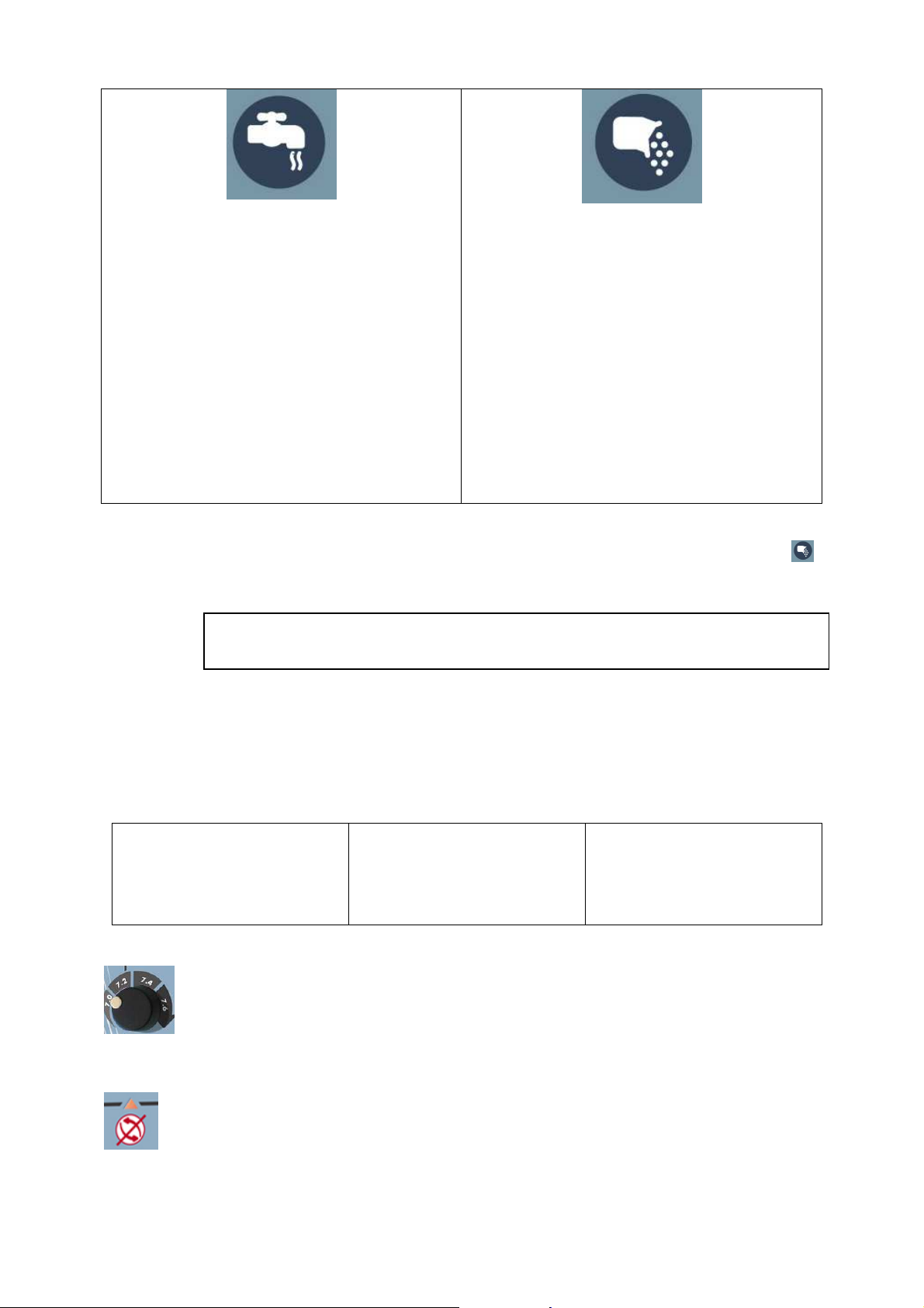
PH REGULATION
pH or the potential Hydrogen measures the degree of acidity of the water. Its value is etween 0 and
14. A solution whose pH is equal to 7 is neutral. If it is less than 7, the solution is acid and if it is
greater than 7, the solution is said to e a ase or alkaline solution.
For ather comfort, treatment efficiency and installation relia ility, the pH of the pool water must e
maintained around 7.
A pH etween 6.8 and 7.6 is generally considered to e correct.
A water which is too acid (pH <6.8) is aggressive for
mucosae, favours the corrosion of metal parts and can
damage plastics (liners).
A water which is too ase (pH>7.8) can also e
aggressive (caustic) and significantly reduce the
efficiency of chlorine. Thus, when the pH increases
from 7.2 to 8.2, the percentage of active chlorine
decreases from 70% to 20%.
In addition, pH has systematically a tendency to
increase due to the presence of salt in the water,
making pH regulation particularly useful.
To o tain the est treatment efficiency, it is therefore indispensa le to maintain the pH of the water
etween 7.0 and 7.6.
For information, the ta le to the right allows
determining the required production time
versus the asin volume, the pH for a water
temperature of 25°C.
Since the water temperature varies during the
season, the filtration time has to e adjusted
to increase production when the water
temperature rises and to decrease production
when the temperature drops.
To avoid any possi le measurement errors, it is recommended to check the calibration of the
probe once a month. To do this, simply follow the instructions in the CALIBRATION section.
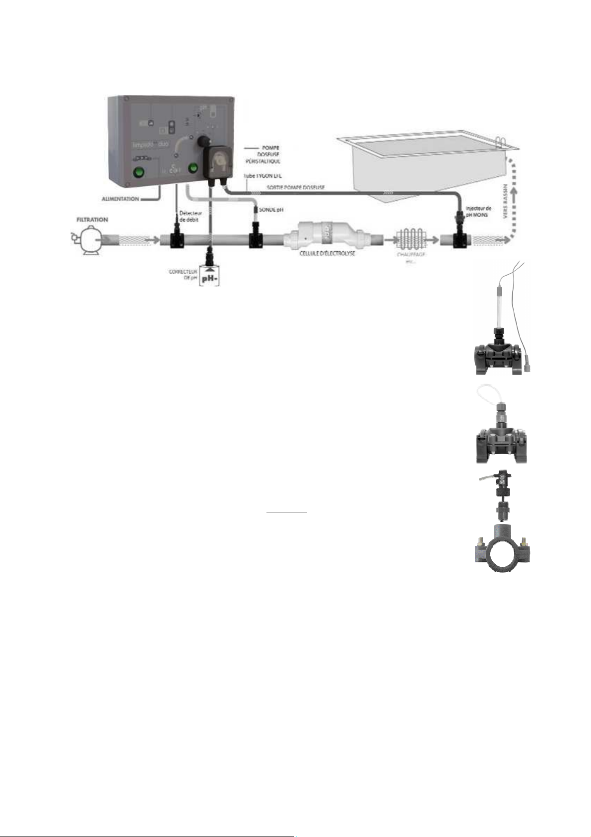
EQUIPMENT DESCRIPTION
ELECTROLYSIS CELL FLOW DETECTOR PH PROBE
Your system’s essential element,
the cell, is equipped with solid
plates made of titanium treated
with ruthenium oxide. It is specially
designed to offer a maximum
service life and to limit
maintenance operations.
The flow detector delivered
with
Limpido EZ Duo
prevents the electrolyser
from operating in the
a sence of flow or during a
ackwashing. It prevents
any risk of hydrogen
accumulation or excessive
heating and thus reinforces
the device’s safety.
The pH pro e is made up of
electrodes which apply a voltage
proportional to the water’s pH. The
pH pro e is fragile and must e
carefully handled. It must e kept
immersed in an aqueous solution.
Volume (m
3
).
pH 40 60 80 100
6.8 2h00 2h50’ 3h50’ 4h50’
7.0 2h10’ 3h15’ 4h20’ 5h30’
7.2 2h30’ 3h40’ 5h00’ 6h15’
7.4 3h00’ 4h30’ 5h50’ 7h20’
7.6 3h40’ 5h25’ 7h15’ 9h00’
7.8 4h40’ 6h50’ 9h15’ 11h30’
Free Chlorine
0
10
20
30
40
50
60
70
80
90
100
5,5 6,0 6,5 7,0 7,5 8,0 8,5 9,0 9,5
pH
%

CCEI
Limpido EZ
Duo
v1.0
Page 4
INSTALLATION
INSTALLING THE PH PROBE
The pH pro e is installed with a pro e holder on a ½’’ dia. clamp. The pro e holder must
e screwed to the clamp with Teflon
®
.
Loosen the pro e holder ring to insert or extract the pro e.
Retighten the ring delicately when the pro e is in the correct position.
INSTALLING THE INJECTOR
The injector allows introducing in the pool the required amount of product. The injector
must e necessarily placed after the pH pro e and as close as possi le to the discharge in
the asin.
The injector must e screwed to the ½’’ dia. clamp with Teflon.
The tu e is positioned on the injector y tightening the injector’s upper nut.
INSTALLING THE FLOW DETECTOR
The detector is mounted on a ¾’’ dia. clamp. After installing the clamp without leaving
any urr capa le of hampering the displacement of the detector, screw the ¾’’ ¾’’
nipple on the clamp with Teflon and then delicately screw the detector to the other
end of the nipple. Whether the flow detector is installed horizontally or vertically, the
arrow engraved on the detector must e pointing in the direction of the water’s flow.
COVER CONTACT
This input must e connected to the drycontact of the cover’s travel limit switch or the
pool’s flap. Thecontact must e dry, that is, a potential free contact, and must e closed when the
cover is closed. Thanks to this contact, Limpido EZ
Duo is informed of the closing of the cover and
therefore can adapt its production. A large part of chlorine consumption is linked to the exposure to
the sun’s ultraviolet radiation and to the frequentation. Therefore, when the pool is covered, the need
for chlorine is greatly reduced. In Automatic mode (thermoregulated), Limpido EZ
Duo divides y
4 the chlorine production. For example, in curve 2, at 22°C, the daily production time drops from 8h
to 2h if the flap is kept closed.
FORCED FILTRATION OPERATION
In Automatic mode (thermoregulated), Limpido EZ
Duo calculates the required production versus
the measured water temperature, ut since the device can produce only during the filtration ranges, it
may prove necessary to force the filtration operation.
When the remaining time to terminate a 24-hour period drops elow the daily calculated production
time, Limpido EZ
Duo
actuates a contact which allows forcing the filtration operation.

CCEI
Limpido EZ
Duo
v1.0
Page 5
This contact must e connected to the ″Forced Operation″ terminal strip of the filtration electrical ox
(Terminal A-B of the CCEI electrical oxes) or to the filtration clock’s contact.
ELECTROLYSIS SERVOING CONTACT
Limpido EZ
Duo may e connected to a programmer or a regulator to control production.
In particular, it may e connected to a Redox (ORP) or Chlorine measuring device. The measuring
device must close the dry contact (totally potential free) when the Redox potential or the chlorine
ratio is less than the desired value.
Limpido EZ
Duo is particularly adapted to operating with OXEO SP. Refer to this device’s manual
for details on how to connect to Limpido EZ
Duo.
In this type of operation, it is recommended to use the Shock/Permanent mode.
ELECTRICAL CONNECTION
For safety reasons, the Limpido EZ
Duo ox must e installed more than 3.50 m from the pool
edge.
The ox must e placed on a flat, sta le support. It must e supplied with a single-phase 230V 50Hz
power supply and e protected y a 30mA differential circuit reaker in accordance with the
applica le standards.
Limpido EZ
Duo is equipped with a flow detector and must not be servoed to filtration.
The electrolysis cell is connected directly to the ox via the specific connector installed at the end of
its cord.
All the other connections are made in the connecting ox as shown elow.
WARNING : it is strongly recommended to have a qualified professional make the
electrical connection.
Flow
detector
Cover contact
To
LIMPIDO EZ
Duo
Electrolysis servoing
Filtration
Start/Stop
To
Filtration
ox
(1)
To travel limit
switch of the
automatic
cover
(1)
To Regulator
(OxeO SP/XP,…)
(1)
To
flow detector
(supplied)
(1)
Optional connection
Jumper to remove to
connect to an
external regulator
externe
230V power supply
permanent and protected
L
N

CCEI
Limpido EZ
Duo
v1.0
Page 6
START-UP
WARNING : ONLY REGULAR ANALYSES ALLOW ADAPTING THE DEVICE’S PARAMETERS
Scrupulously following the steps elow will ensure a trou le-free start-up.
CHECKING THE SALT RATIO
Limpido EZ Duo is designed to operate with a water conductivity corresponding to a salt content
etween 2.5g/l and 5g/l at 25°C.
To check with precision the salt ratio of your pool, we recommend using a conductivity tester. This
very simple to use instrument allows a direct readout of the salt ratio in g/l. In addition, there are
analysis strips to allow efficiently checking your water’s salt content.
When the salt content is inappropriate, Limpido EZ Duo stops the production and turns on the
″overproduction″ indicator light in case of an excess amount of salt or the ″underproduction″ indicator
light in case of a lack of salt. In case one of these indicator lights is lit, first make sure that the cell is
correctly connected to the ox and then that it is in good condition and make the necessary
corrections on the pool water.
Water conductivity is not only proportional to the salt content, ut also depends on the temperature at
the rate of 2.2% per degree Celsius (°C).
10°C 15°C 20°C 25°C 30°C 35°C 40°C
Min 3.3 3.1 2.8 2.5 2.2 2.0 1.7
Ideal 4.7 4.3 3.9 3.5 3.1 2.7 2.3
Max 6.7 6.1 5.6 5 4.5 3.9 3.4
Salt content in g/l
At 35°C the max salt ratio, therefore, goes from 5g/l to 3.9g/l.
STABILISER
Chlorine is gaseous at room temperature. Its solid form (pe les, granules, etc.) is o tained y
association with a molecule of cyanuric acid. This cyanuric acid acts as a sta iliser since it protects the
chlorine from the degradation that the sun’s ultraviolet (UV) radiation su jects it to. On the other
hand, this cyanuric acid is not consumed and inexora ly accumulates in pools treated with chlorine
pe les and finally inhi its the chlorine potential. For pu lic swimming pools, the maximum
concentration of cyanuric acid is set at 80 ppm (or mg/l).
The treatment y electrolysis of the salt prevents such overdosing in cyanuric acid. However, it may
prove useful to add etween 25 and 50 ppm (or mg/l) of sta iliser when the pool is very exposed to
sun and the chlorine concentration is insufficient.
In fact, in right sunlight, 90% of the free chlorine is destroyed in two to three hours in the a sence
of cyanuric acid, while this proportion is lowered to 15% with 30ppm of sta iliser (cyanuric acid).
CHECKING TPA AND TH
At the installation time, it is recommended to test or have tested y a specialist the TPA (Total
Phenolphthalein Alkalinity) and/or TH (Titration for Hardness) of the pool water. Both measurements
are generally closely related and are often expressed in degrees Fahrenheit (°F). If TPA and TH are
different, retain an average value of oth of these measurements.
However, it is important to point out that a very soft water (TPA/TH <10°F) which offers the
advantage of avoiding scaling is very corrosive, and its pH is very unsta le.
Conversely, a very hard water (>35°F) which has a pH difficult to correct is very irritating for the skin
and causes a rapid scaling of the installations. In extreme cases, it is therefore recommended to
correct the TPA and the TH using appropriate chemical products.
Warning : the pH correctors used in pools are very corrosive and can have a harmful effect on health
and on the environment. These chemical products must e handled with precaution and e stored in
adapted premises.

CCEI
Limpido EZ
Duo
v1.0
Page 7
CALIBRATION
Before proceeding with the so-called cali ration, it is necessary to :
♦Set the set point to 7.0
♦Stop filtration (flow indicator light turns off)
♦Take the pro e out of the pro e holder, and then rinse and dry the probe.
♦Plug the pro e holder (with a 5-cent coin).
Then the cali ration takes place as follows:
♦Plunge the pro e in the 650 mV standard solution
♦Adjust the calibration screw with the supplied adjusting screwdriver so that the central
indicator light
(green) turns on.
♦Turn to the minus sign (-) if the left indicator light
⊳
(red) is lit.
♦Turn to the plus sign (+) if the right indicator light
(red) is lit.
When the central indicator light
(green) is lit, the device is cali rated.
♦Reinstall the pro e in the pool piping
♦Restart filtration (the flow indicator light turns on)
The cali ration procedure is terminated.
To avert errors due to the pro e aging, cali ration must e regularly checked (approximately once a
month).
Important : after opening, the cali ration solution can only be preserved for a few months. It
must e renewed at least each season and even several times if your installation operates all year
long.

CCEI
Limpido EZ
Duo
v1.0
Page 8
OPERATION
ELECTROLYSIS
INDICATOR LIGHTS AND BUTTONS
Electrolysis and pH regulation operate independently and can e started with the corresponding
switch.
A luminous switch allows switching on the device. The indicator lights indicate the Limpido EZ
Duo’s operating state, while the key is used to select its operating mode.
MODE CHOICE
The key selects the electrolyser’s operating mode.
Shock / Permanent Mode (Indicator light unlit)
The device produces as long as the filtration is running.
Automatic / Thermoregulated Mode (Indicator light lit)
The production time is adjusted versus temperature. Depending on the pool
size and its frequentation, a choice of 3 thermoregulation curves is availa le.
CURVE CHOICE
In Automatic mode, pressing and holding down the key for 3 seconds
allows changing the adapted thermoregulation curve.
The indicator light corresponding to the active curve flashes. To select the
next curve, riefly press the key.
To save the desired curve, press and hold down the key again for 3
seconds.
Limpido EZ
Duo recalculates the optimum production time and starts a
new cycle.
The curve used y the device is displayed whenever production starts in Automatic mode
(thermoregulated). The green indicator light corresponding to the activated curve flashes for a few
seconds.
pH Setpoint
adjusting utton
pH Re
gulation
Start/Stop switch
Flow
indicator light
Electrolysis
Start/Stop switch
Under
production
indicator light
Cover
indicator
light
Thermoregulated
Mode indicator light
Overdose
indicator
light
pH 7
cali ration
screw
pH
indicator
C
3
C
2
C1
Polarity
indicator
Over
production
indicator light
P
roduction
indicator

CCEI
Limpido EZ
Duo
v1.0
Page 9
LOW TEMPERATURE AND TEMPERATURE FAULT
In the Automatic mode (thermoregulated), the device stops producing when the
temperature is less than 10°C. The thermoregulated indicator light intermittently turns on
(1 periodic flash).
When the temperature rises a ove 11°C, Limpido EZ
Duo automatically resumes the
treatment.
In case the device detects a temperature measurement fault, Limpido EZ
Duo
switches to the Permanent mode (Shock).
When the daily filtration duration is insufficient to allow producing the necessary time (Automatic
mode), Limpido EZ
Duo actuates a contact to force the running of the filtration pump (cf § Forced
filtration) and indicates its state y 5 periodic flashes of the thermoregulated indicator light.
Thermoregulation
indicator light
Description of the state
Unlit Shock mode
Lit Thermoregulated automatic mode
1 periodic flash Water temperature too low to produce (<10°C)
5 periodic flashes Filtration insufficient / Forced filtration
Permanently flashing Temperature measurement error
POLARITY INDICATOR
The cell is cleaned y a periodic polarity reversal.
Two indicator lights indicate the production polarity. To preserve the service life of the
cell’s electrodes, a pause of several minutes separates the changing of polarity. During
this pause, oth polarity indicator lights alternately flash.
PRODUCTION INDICATOR
The production indicator allows checking the production level.
The production level is given y green and yellow indicator lights.
If no green indicator light is lit despite a production set to the
maximum, then it is necessary to check the salt ratio.
If the yellow Low production indicator light and at least one of the
three green indicator lights are lit, it means that the production
level is optimum.
Limpido EZ
Duo is equipped with a protection device which
stops production as soon as a production fault is detected.
Low
production
Product
ion
OK
High
production

CCEI
Limpido EZ
Duo
v1.0
Page 10
Overproduction
This alert is generally caused y an excessive
amount of salt in the pool or an increase of the
water temperature.
To avoid having an excess current damage the
cell and the control relays, the device cuts off
production as soon as such a situation is
detected.
Overproduction occurs mostly at the moment salt
is added to the pool when the device is started
efore the salt is completely diluted.
Check the salt ratio ; if the ratio exceeds 5g/l, the
water should e drained and then the pool should
e filled until a salt ratio less than or equal to 5g/l
is o tained.
Underproduction
To avoid damaging the cell plates during an
operation with not enough salt, the device is
equipped with a detection device which stops the
treatment as soon as there is a lack of salt.
Check the salt ratio ; if the ratio is less than
2.5g/l (2500ppm), salt has to e added and
production may e restarted only when the salt is
completely diluted.
If the salt ratio is correct, then either the cell is
scaled or it is worn out. Consequently, the cell
should e dismounted and the state of the plates
checked. If necessary, descale it (cf
Cleaning the
cell
).
In Automatic mode (thermoregulated) and if Limpido EZ
Duo could not produce throughout the
required time despite forced operation, the device signals underproduction y flashing the
indicator light. In this case, the daily filtration time should e increased.
Since water conductivity decreases with temperature, the chlorine production decreases when the
water cools. This phenomenon is taken advantage of to limit production in winter when the amount of
chlorine needed to disinfect ecomes very low.
PH REGULATION
PH INDICATOR
Indicator light ⊳
When the left indicator light is lit, it
means that the water’s pH is less
than the setpoint value : The
dosing pump is stopped.
Indicator light
When the central indicator light is
lit, the water’s pH is equal to the
setpoint value : The dosing pump
is stopped.
Indicator light
When the right indicator light is lit,
the water’s pH is greater than the
setpoint value : The dosing pump
is running.
PH SETPOINT
The rotary switch allows selecting one of the four setpoint values :
7.0 / 7.2 / 7.4 / 7.6
This value defines the threshold above which the pump starts running to add acid to the
pool.
OVERDOSE INDICATOR LIGHT
To reduce the risk of overdose caused y a possi le pH measurement error, Limpido EZ
Duo inhi its the pump from running if the pH is not corrected within 3h. Thus, the maximum
volume injected in 24h is limited to 2.7 litres.
To cancel an overproduction fault, it is necessary to stop and then
restart the device.

CCEI
Limpido EZ
Duo
v1.0
Page 11
MAINTENANCE
SERVICING THE PH PROBE
When a pH pro e is plunged in water, a film forms around the glass ul at its end, and this film
increases in thickness over time. This invisi le film induces an increasingly longer response time,
degradation of the slope and a drift from point 0 (pH 7). The drift from point 0 can e easily
compensated for y a regular cali ration. A temperature increase is also an important aging factor.
Pro e preservation
Never keep the pro e in distilled water.
Pro es stored ″wet″ can e immediately reused ; pro es stored "dry" necessitate a rehydration of
several hours, ut they will e less "aged".
Pro e regeneration
A pro e’s service life can e extended y a periodic regeneration.
To regenerate a pro e, simply soak the pro e in a diluted hydrochloric acid solution (HCl 0.1M).
To o tain such a solution, add a few drops (8 to 10) of hydrochloric acid (HCl at 37%) in half a glass
(5cl) of tap water.
WINTERING
In winter, and if climate conditions allow it, the treatment may e maintained while significantly
reducing the frequency. An 8-hour filtration cycle every 15 days is sufficient in most cases.
However, the salt ratio must continue to e monitored to keep the cell from operating in a water with
too low a salt content (<2g/l).
In case a tarpaulin or a cover is used, the chlorine is protected from UV radiation. To prevent an over-
chlorination, the production level should e decreased accordingly.
To allow Limpido EZ
Duo to operate with cold water ( elow 18°C), the salt ratio has to e
increased to 5g/l.
ADDING SALT
When the salt level drops elow 2.5g/l, it is indispensa le to add salt in the asin.
It is recommended to use salt specially treated for swimming pools and containing sta ilisers. The
electrolyser’s efficiency will e significantly improved.
At the eginning of the season, we recommend checking the salt ratio and adjusting it to 4g/l.
Depending on the measured salt ratio, the amounts of salt to e added are as follows :
Basin volume in m3
Measured
ratio
40 50 60 70 80 90
2.5g/l 60 75 90 105 120 135
3g/l 40 50 60 70 80 90
3.5g/l 20 25 30 35 40 45
Salt weight in kg to e added to reach 4g/l
CLEANING THE CELL
When the indicated production remains low despite a correct salt ratio, the cell’s condition should e
checked and it should e cleaned if scales are visi le on the plates.
To clean the cell, plug one end and pour diluted acid in it (HCl at 10% is recommended). Let the acid
act for several hours.
This operation must e performed with the greatest caution and the utilisation prescriptions for the
used acid must e respected.

CCEI
Limpido EZ
Duo
v1.0
Page 12
L
IMPIDO
EZ
D
UO
Date of sale : ..........................................................................................
Serial num er :........................................................................................
Declaration
The Bleu Electrique SAS Company (FR 47 403 521 693) declares that the
LIMPIDO EZ Duo product satisfies the safety and electromagnetic
compati ility requirements of the European directives 2006/95/EC and
2004/108/EEC.
Emmanuel Baret
Marseilles, 19/02/2014
Distributor Stamp
This manual suits for next models
1
Table of contents
Other ccei Lighting Equipment manuals

ccei
ccei Brio PK10R400 Owner's manual

ccei
ccei Zelia ZLT User manual

ccei
ccei Brio WX-100 User manual

ccei
ccei Mini Brio X15CA Owner's manual

ccei
ccei Mini BRIO M12CA User manual

ccei
ccei PF10R511 Owner's manual

ccei
ccei BRIO A300C Manual

ccei
ccei Mini Brio 2 X3 color Owner's manual

ccei
ccei NIVA 3 Owner's manual

ccei
ccei LIMPIDO LTE DUO User manual