CDVI DIGIWAY PLUS User manual

EN
Inwards and Outwards Door Operator,
Door Automation
DIGIWAY Plus
*
WARRANTY
YEAR
2

EN EN
DIGIWAY Plus
Inward or Outward Door Operator
2
General safety instructions and precautionsGeneral safety instructions and precautions 33
..............Machinery Directive 3Machinery Directive 3
..............Instructions of useInstructions of use 55
..............Declaration of the ManufacturerDeclaration of the Manufacturer 55
1]1] IDENTIFYING PRODUCT AND PARTSIDENTIFYING PRODUCT AND PARTS 66
..............AccessoriesAccessories 77
..............Mounting guideMounting guide 88
..............Technical specicationsTechnical specications 99
2] I2] INSTALLATIONNSTALLATION 1111
..............Sliding arm versionSliding arm version 1111
..............Articulated arm versionArticulated arm version 1212
..............Wiring diagramWiring diagram 1414
..............Electrical connectionsElectrical connections 1515
..............LED messagesLED messages 1818
..............BatteryBattery 1818
3]3] SYSTEM CONFIGURATIONS AND SETTINGSSYSTEM CONFIGURATIONS AND SETTINGS 1919
•• Step I: Set-upStep I: Set-up 1919
•• Step II: CongurationStep II: Conguration 2020
•• Step III: Door calibrationStep III: Door calibration 2222
•• StepStep IV: AdjustingIV: Adjusting 2323
•• StepStep V: Advanced adjustingV: Advanced adjusting 2525
..............Disabled persons access settingsDisabled persons access settings 2929
..............Remote controls management 30Remote controls management 30
..............Menu ServiceMenu Service 3131
..............Reset to factory default & system resetReset to factory default & system reset 3232
4]4] DOUBLE DOOR CONFIGURATIONDOUBLE DOOR CONFIGURATION 3333
5]5] INSTRUCTIONS FOR USEINSTRUCTIONS FOR USE 3838
6]6] MAINTENACEMAINTENACE 3939
Summary pageSummary page

EN EN DIGIWAY Plus
Inward or Outward Door Operator
3
This manual is intended for professional installers, adequately trained.This manual is intended for professional installers, adequately trained.
Installation and connections must be carried out in accordance with Good WorkingInstallation and connections must be carried out in accordance with Good Working
Practice and in compliance with the current Regulations. Poor installation could bePractice and in compliance with the current Regulations. Poor installation could be
source of a health & safety hazard.source of a health & safety hazard.
First check all of the existing door and frame structure - verify its integrity, stability andFirst check all of the existing door and frame structure - verify its integrity, stability and
strength.strength.
If necessary modify the structure in order to make it standard, being aware of all theIf necessary modify the structure in order to make it standard, being aware of all the
possible problems that could occur during normal use.possible problems that could occur during normal use.
Verify that all the zones where there is a risk of crushing, dragging, shearing and otherVerify that all the zones where there is a risk of crushing, dragging, shearing and other
dangers, are protected by electronic safety, safety boards or barriers.dangers, are protected by electronic safety, safety boards or barriers.
This can be achieved if the distance does not exceed 8 mm. However, to avoid entrapmentThis can be achieved if the distance does not exceed 8 mm. However, to avoid entrapment
for the various parts of the body, the following distances are considered sufcient:for the various parts of the body, the following distances are considered sufcient:
Hand ngers > 25 mmHand ngers > 25 mm
Foot > 50 mmFoot > 50 mm
Head > 300 mmHead > 300 mm
Body > 500 mmBody > 500 mm
The forces developed by the complete system must comply with the current standardsThe forces developed by the complete system must comply with the current standards
and, where this is not possible, protect the zones with electronic safety devices.and, where this is not possible, protect the zones with electronic safety devices.
Apply hazardous area notices required by the applicable regulations. Before the actuatorApply hazardous area notices required by the applicable regulations. Before the actuator
is connected, make sure that the plate details correspond to those of the mains poweris connected, make sure that the plate details correspond to those of the mains power
and that there is a differential circuit-breaker and an adequate protection againstand that there is a differential circuit-breaker and an adequate protection against
overcurrents on the supply side of the system.overcurrents on the supply side of the system.
Fit a Dual Pole disconnection switch with contact opening gap of at least of 3 mm.Fit a Dual Pole disconnection switch with contact opening gap of at least of 3 mm.
Interrupt the power supply before opening the cover of the actuator for any maintenanceInterrupt the power supply before opening the cover of the actuator for any maintenance
or repairing intervention.or repairing intervention.
Handling of electronic parts must be carried out wearing grounded antistatic braceletsHandling of electronic parts must be carried out wearing grounded antistatic bracelets
to avoid any static damage.to avoid any static damage.
Servicing the actuator is of fundamental importance if the system is to operate correctlyServicing the actuator is of fundamental importance if the system is to operate correctly
and safely.and safely.
Comply with the manufacturer’s instructions described in this manual.Comply with the manufacturer’s instructions described in this manual.
Only use genuine spare parts if replacements or repairs are required. The motorOnly use genuine spare parts if replacements or repairs are required. The motor
manufacturer declines any responsibility if component parts tted are not compatible manufacturer declines any responsibility if component parts tted are not compatible
with safe and correct operation. The actuator must be installed inside only.with safe and correct operation. The actuator must be installed inside only.
IMPORTANT SAFETYIMPORTANT SAFETY
PRECAUTIONSPRECAUTIONS
The present document contains important precautions for safe use and operation.The present document contains important precautions for safe use and operation.
Read the instructionsRead the instructions carefullycarefully before commencing the installation. Keep thisbefore commencing the installation. Keep this
document even after installation.document even after installation.
!

EN EN
DIGIWAY Plus
Inward or Outward Door Operator
4
The manufacturer declines all liability for damage caused by outdoor assembly withoutThe manufacturer declines all liability for damage caused by outdoor assembly without
adequate protection.adequate protection.
This product cannot be installed in places with an explosive atmosphere or in theThis product cannot be installed in places with an explosive atmosphere or in the
presence of ammable fumes or gases.presence of ammable fumes or gases.
Only use genuine spare parts if replacements or repairs are required. The motorOnly use genuine spare parts if replacements or repairs are required. The motor
manufacturer declines any responsibility if component parts tted are not compatible manufacturer declines any responsibility if component parts tted are not compatible
with safe and correct operation. The actuator must be installed inside only.with safe and correct operation. The actuator must be installed inside only.
The manufacturer declines all liability for damage caused by outdoor assembly withoutThe manufacturer declines all liability for damage caused by outdoor assembly without
adequate protection.adequate protection.
This product cannot be installed in places with an explosive atmosphere or in theThis product cannot be installed in places with an explosive atmosphere or in the
presence of ammable fumes or gases.presence of ammable fumes or gases.
Only use genuine spare parts if replacements or repairs are required.Only use genuine spare parts if replacements or repairs are required.
The appliance can be used by children aged 8 or under and by persons with reducedThe appliance can be used by children aged 8 or under and by persons with reduced
physical, sensory or mental abilities, without experience or necessary knowledge,physical, sensory or mental abilities, without experience or necessary knowledge,
provided they are under surveillance or after they have received instructions concerningprovided they are under surveillance or after they have received instructions concerning
safe use of the appliance and an understanding of the dangers inherent to it.safe use of the appliance and an understanding of the dangers inherent to it.
The sound pressure level, weighted A, of the noise emitted by theThe sound pressure level, weighted A, of the noise emitted by the device is less thandevice is less than
70 dB (A).70 dB (A).
If a passive emergency button is installed, it must be installed in view of the door but
away from moving parts.
Unless this is protected by a security key, it must be installed at a minimum height of
1.5 m and not accessible to the public
Children must not play with the appliance. Cleaning and maintenance intended for use
by the user must not be carried out by children without supervision.
Machinery DirectiveMachinery Directive
Automatic pedestrian doors fall into the application eld of the Machinery Directive Automatic pedestrian doors fall into the application eld of the Machinery Directive
(2006/42/CE).(2006/42/CE).
This provides that the installer who motorizes a door becomes the manufacturer of aThis provides that the installer who motorizes a door becomes the manufacturer of a
machinery and so he must:machinery and so he must:
1. Prepare the Technical Construction File (which must contain the documents indicated1. Prepare the Technical Construction File (which must contain the documents indicated
in Annex V of the Machinery Directive) and must be kept and placed at the disposal ofin Annex V of the Machinery Directive) and must be kept and placed at the disposal of
competent national authorities for at least ten years from the date of manufacture ofcompetent national authorities for at least ten years from the date of manufacture of
the motorised door.the motorised door.
2. Draft the EC Declaration of Conformity in accordance with Annex II-A of the Machinery2. Draft the EC Declaration of Conformity in accordance with Annex II-A of the Machinery
DirectiveDirective
3. Afx the CE marking on the power operated door in accordance with point 1.7.3 of 3. Afx the CE marking on the power operated door in accordance with point 1.7.3 of
Annex I of the Machinery Directive.Annex I of the Machinery Directive.

EN EN DIGIWAY Plus
Inward or Outward Door Operator
5
vvvvvvvvvv
The installer must consign to the customer the following documents :The installer must consign to the customer the following documents :
1. Instructions on how to operate and safely use the system.1. Instructions on how to operate and safely use the system.
2. Routine maintenance instructions.2. Routine maintenance instructions.
3. Declaration of conformity.3. Declaration of conformity.
4. Maintenance register.4. Maintenance register.
Instructions for useInstructions for use
The operator DIGIWAY type DWPS102XX, DWPD102XX belongs to the Service Class 5The operator DIGIWAY type DWPS102XX, DWPD102XX belongs to the Service Class 5
(600 cycles a day for 5 years min).(600 cycles a day for 5 years min).
Applications: HEAVY DUTY, for pedestrian accesses to institutional complexes with veryApplications: HEAVY DUTY, for pedestrian accesses to institutional complexes with very
intense use.intense use.
Declaration of the ManufacturerDeclaration of the Manufacturer
( according to Directive( according to Directive 2006/42/CE2006/42/CE, Annex II part B ), Annex II part B )
The ManufacturerThe Manufacturer
CDVI WIRELESS SPA - CDVI GroupCDVI WIRELESS SPA - CDVI Group
Via Piave,23Via Piave,23
31020 S.Pietro di Feletto (TV)31020 S.Pietro di Feletto (TV)
ITALYITALY
Herewith declares that the automatic operator for swing doorsHerewith declares that the automatic operator for swing doors
Brand : DIGIWAYBrand : DIGIWAY
Model : DIGIWAY PLUSModel : DIGIWAY PLUS
Types : DWPS102XX, DWDP102XXTypes : DWPS102XX, DWDP102XX
- constitutes a “partly completed machinery” and it is intended to be incorpored into machinery- constitutes a “partly completed machinery” and it is intended to be incorpored into machinery
or to be assembled with other machinery to constitute a machinery covered by Directiveor to be assembled with other machinery to constitute a machinery covered by Directive
2006/42/CE;2006/42/CE;
- complies with the following Directives :- complies with the following Directives :
2006/95/CE ( Low Voltage Directive )2006/95/CE ( Low Voltage Directive )
2004/108/CE ( Electromagnetic Compatibility Directive )2004/108/CE ( Electromagnetic Compatibility Directive )
2014/53/UE ( RED )2014/53/UE ( RED )
European Standard EN16005 : Power Operated doorsets - Safety in UseEuropean Standard EN16005 : Power Operated doorsets - Safety in Use
- it is not allowed to put the machinery into service until the machinery into which it has to be- it is not allowed to put the machinery into service until the machinery into which it has to be
incorporated or of which it has to be a component has been found and declarated to be inincorporated or of which it has to be a component has been found and declarated to be in
compliance with the provisions of the Directivecompliance with the provisions of the Directive 2006/42/CE2006/42/CE..
S.Pietro di Feletto,S.Pietro di Feletto, 01/11/201701/11/2017
G. Massimo Dalle CarbonareG. Massimo Dalle Carbonare
( Product manager )( Product manager )

EN EN
DIGIWAY Plus
Inward or Outward Door Operator
6
1] IDENTIFYING THE PRODUCT AND ITS PARTS1] IDENTIFYING THE PRODUCT AND ITS PARTS
DIGIWAY type DWPx102xx is an indoor operator for swing doors, with integrated electronicDIGIWAY type DWPx102xx is an indoor operator for swing doors, with integrated electronic
controller and radio receiver. The opening and closing motion is electromechanical withcontroller and radio receiver. The opening and closing motion is electromechanical with
backup battery which assures the operation in cases of power failure.backup battery which assures the operation in cases of power failure.
The following versions are available:The following versions are available:
LegendLegend
1 - Anodized aluminium cover1 - Anodized aluminium cover
2 - Motor shaft2 - Motor shaft 9 -9 - EncoderEncoder
3 - Status led LP3 - Status led LP 10 - Slot for cover opening10 - Slot for cover opening
4 -4 - Receiver CardReceiver Card 11 -11 - Toroidal transformerToroidal transformer
5 - Display LCD 12 -5 - Display LCD 12 - Backup batteryBackup battery
6 - 5-buttons keyboard6 - 5-buttons keyboard 13 -13 - Battery cable with protection fuseBattery cable with protection fuse
7 -7 - Gear boxGear box 14 -14 - Jumper for external selector exclusionJumper for external selector exclusion
8 -8 - MotoriductorMotoriductor 15 -15 - Operating mode selectorOperating mode selector
P/N Reference Description
F0543000093F0543000093 DWPS102SCD Single door operator for inswing doors with sliding armSingle door operator for inswing doors with sliding arm
F0543000094F0543000094 DWPS102ACD Single door operator for outswing doors with articulated armSingle door operator for outswing doors with articulated arm
F0543000095 DWPS102UCD Single door operator for inswing or outswing doors with universal armSingle door operator for inswing or outswing doors with universal arm
7 8 9
56
3
12
4
The operator is suitable for swing doors with max width of 1.2 m or max weight ofThe operator is suitable for swing doors with max width of 1.2 m or max weight of
120kg (refer to diagram on page 7). At max speed the door can open and close within120kg (refer to diagram on page 7). At max speed the door can open and close within
3 sec. (90°), depending on door weight and dimensions.3 sec. (90°), depending on door weight and dimensions.
See the technical specications in the following pages of this manual.See the technical specications in the following pages of this manual.
Warning : the operator is suitable only for top-jamb xing. Door leaf Warning : the operator is suitable only for top-jamb xing. Door leaf
xing is not allowed.xing is not allowed.
11
10
12 13 15
14

EN EN DIGIWAY Plus
Inward or Outward Door Operator
7
ArticleArticle
Description Screw for
wallplugs
SX 8
Wallplugs
SX 8 Self tapping
screws Screw
M6x14 Mounting
plate Mounting
template
Q.tyQ.ty 666644771111
Description P/N F-code
Kit articulatedKit articulated
armarm DWKBA F0543000030
Kit sliding armKit sliding arm DWKBS F0543000031
Kit universalKit universal
armarm DWKBU F0543000122
Extension 55Extension 55
mmmm DWSE F0543000033
Extension 30Extension 30
mmmm DWSE30 F0543000123
Extension 80Extension 80
mmmm DWSE80 F0543000136
Double doorDouble door
cablecable DWPCS F0543000124
Mounting toolsMounting tools
kitkit DWTK F0543000156
AccessoriesAccessories
Mounting kitMounting kit

EN EN
DIGIWAY Plus
Inward or Outward Door Operator
8
Mounting diagramMounting diagram
Cover lift pointCover lift point
Sliding armSliding arm
Articulated armArticulated arm
The universal arm can be assembled for use with an inward opening door (pull - sliiding)The universal arm can be assembled for use with an inward opening door (pull - sliiding)
or an outward opening door (push - articulated). The DWP comes with an assembledor an outward opening door (push - articulated). The DWP comes with an assembled
sliding arm as standard. To change the arm assembly to articulated; remove the slidingsliding arm as standard. To change the arm assembly to articulated; remove the sliding
block by unscrewing from the arm (requires a 13mm AF spanner), once removedblock by unscrewing from the arm (requires a 13mm AF spanner), once removed
assemble the adjustable articulated fore arm to the xed by screwing xed bolt into assemble the adjustable articulated fore arm to the xed by screwing xed bolt into
the threaded hole left by removing the sliding block.the threaded hole left by removing the sliding block.
Turn clockwiseTurn clockwise
Turn anti-clockwiseTurn anti-clockwise
Screw M6x14 Screw M6x14
providedprovided
Screw M6x14 Screw M6x14
providedprovided
Screw M6x14 Screw M6x14
providedprovided
M6x14 M6x14
M6x14 M6x14
M6x14 M6x14
Plugs SX8Plugs SX8
Screws for plugs SX8 Screws for plugs SX8
WasherWasher
Universal ArmUniversal Arm

EN EN DIGIWAY Plus
Inward or Outward Door Operator
9
Technical specicationsTechnical specications
General specicationsGeneral specications
PowerPower 230 Vac - 50 Hz 15 Nm230 Vac - 50 Hz 15 Nm
Motor torqueMotor torque 15 Nm15 Nm
Max powerMax power 50 W50 W
Operating classOperating class 5 (heavy duty)5 (heavy duty)
BatteryBattery 12 Vdc 1,3 Ah12 Vdc 1,3 Ah
Overall dimensionsOverall dimensions 511 x 90 x 110 mm511 x 90 x 110 mm
WeightWeight 5kg5kg
Operating temperatureOperating temperature -10°C ÷ +55°C-10°C ÷ +55°C
IP GradeIP Grade IP40IP40
Opening / closing timeOpening / closing time 3 ÷ 15 sec.3 ÷ 15 sec.
Pause timePause time 3 ÷ 90 sec.3 ÷ 90 sec.
Power for auxiliary devicesPower for auxiliary devices 13.5 Vdc / 500 mA [max]13.5 Vdc / 500 mA [max]
Power for electrolockPower for electrolock 12 Vdc / 1A [max]12 Vdc / 1A [max]
Electrolock output relayElectrolock output relay (C-NO-NC) 10A / 12V(C-NO-NC) 10A / 12V
Open door output relayOpen door output relay (C-NO) - 24 VA(C-NO) - 24 VA
Electrolock hold timeElectrolock hold time AdjustableAdjustable [0.l1 ÷ 5 min][0.l1 ÷ 5 min]
Power failure autonomyPower failure autonomy 270 cycles / 16 hours270 cycles / 16 hours
RX memoryRX memory Keeloq® Hopping Code 50 transmittersKeeloq® Hopping Code 50 transmitters
Integrated receiver main specicationsIntegrated receiver main specications 433.92 MHz ASK / -107 dBm433.92 MHz ASK / -107 dBm
Fire voltage inputFire voltage input 24 ÷ 48 Vac/dc24 ÷ 48 Vac/dc
Use conditionsUse conditions
Zone AZone A : Very intense use : 600 cycles / day: Very intense use : 600 cycles / day
Zone BZone B :: Intense useIntense use : 200-300: 200-300 cycles / daycycles / day
Zone CZone C : Use at reduced speed: Use at reduced speed
Zone D : Not allowedZone D : Not allowed
Max Door opening angleMax Door opening angle
Leaf widthLeaf width
Leaf weightLeaf weight

EN EN
DIGIWAY Plus
Inward or Outward Door Operator
10
Main featuresMain features
•• Operating modes: Fully automatic, Door open, Door free/ operation off;Operating modes: Fully automatic, Door open, Door free/ operation off;
•• Operating with single door, double door, with or without leaf overlapping;Operating with single door, double door, with or without leaf overlapping;
•• Guided procedure for door travel limits characterisation;Guided procedure for door travel limits characterisation;
•• Adjustable motor torque during open and close phases;Adjustable motor torque during open and close phases;
•• Remote controls memorization and management;Remote controls memorization and management;
•• Auto slow down during approach to door limits;Auto slow down during approach to door limits;
•• Push & Go / Pull & Go function;Push & Go / Pull & Go function;
•• Pause Time, Max Speed, Torque, Velocity adjustable;Pause Time, Max Speed, Torque, Velocity adjustable;
•• Opening Jolt fully adjustable;Opening Jolt fully adjustable;
•• Status bicolor LED;Status bicolor LED;
•• Electrolock hold time and torque adjustable;Electrolock hold time and torque adjustable;
•• Opening Jolt parameters adjustable;Opening Jolt parameters adjustable;
•• Spring mode (Door always free, spring simulation with auto closing);Spring mode (Door always free, spring simulation with auto closing);
•• Stop and reopen photocell inputs;Stop and reopen photocell inputs;
•• “Fire mode”;“Fire mode”;
•• Night / day mode;Night / day mode;
•• Door open output relay (gives open volt free contact whilst door is open).Door open output relay (gives open volt free contact whilst door is open).
Electronic card specicationsElectronic card specications
Operating modes:Operating modes: Automatic ( I ) - Door free ( 0 ) - Door always open (II)Automatic ( I ) - Door free ( 0 ) - Door always open (II)
Inputs:Inputs: Re-open photocells ( NC)Re-open photocells ( NC)
Stop photocells ( NC )Stop photocells ( NC )
Door Alway openDoor Alway open ( NO )( NO )
Door free ( NO )Door free ( NO )
External Radar ( NO )External Radar ( NO )
Internal Radar ( NO )Internal Radar ( NO )
Day / Night selection ( NO )Day / Night selection ( NO )
Open / Close command ( NO )Open / Close command ( NO )
Fire alarm voltage ( +V, -V ) [optoisolated]Fire alarm voltage ( +V, -V ) [optoisolated]
Outputs:Outputs: Door open contact ( C-NO )Door open contact ( C-NO )
External devices power 13,5 Vdc / 500 mAExternal devices power 13,5 Vdc / 500 mA
Electrolock output contacts ( C-NO-NC )Electrolock output contacts ( C-NO-NC )
Electrolock power 12 Vdc / 1 AElectrolock power 12 Vdc / 1 A
Test for safety devices ( FTC- FTC-S )Test for safety devices ( FTC- FTC-S )

EN EN DIGIWAY Plus
Inward or Outward Door Operator
11
2] INSTALLATION2] INSTALLATION
Sliding arm versionSliding arm version
Important: Check the integrity of the door that is to be automated, veriying Important: Check the integrity of the door that is to be automated, veriying
the operation in both directions is smooth without any friction from the closedthe operation in both directions is smooth without any friction from the closed
to open position and the open to closed position. If this is not the case, maketo open position and the open to closed position. If this is not the case, make
any repairs or improvements necessary to achieve a smooth operation of theany repairs or improvements necessary to achieve a smooth operation of the
door. Remove any manually operated locking mechanism unless it is to bedoor. Remove any manually operated locking mechanism unless it is to be
used with a strike. A door stop is not required to complete the opening cycle.used with a strike. A door stop is not required to complete the opening cycle.
Warning:Warning: Any existing closing device should be removed to allow the door to moveAny existing closing device should be removed to allow the door to move
freely. Hydraulic devices MUST be replaced with dummy units as adjusting the devicefreely. Hydraulic devices MUST be replaced with dummy units as adjusting the device
will not allow the Digiway to operate correctly.will not allow the Digiway to operate correctly.
Parameter Value
(mm) Description
AA240240 Door hinge – motor axis distanceDoor hinge – motor axis distance
BB3535 Backplate – guide distanceBackplate – guide distance
CC100100 Motor axis - guide edgeMotor axis - guide edge
DD500500 Guide widthGuide width
EE18,518,5 Distance hinges - backplate holeDistance hinges - backplate hole
FF70,570,5 Motor axis - vertical plane distanceMotor axis - vertical plane distance

EN EN
DIGIWAY Plus
Inward or Outward Door Operator
12
A
B
The Sliding Arm is designed for pull applications, inward opening doors.The Sliding Arm is designed for pull applications, inward opening doors.
1) Using the dimensions of the motor and the template provided (see inside of the1) Using the dimensions of the motor and the template provided (see inside of the
box sleeve) locate the xing positions and cable holes; box sleeve) locate the xing positions and cable holes;
2) Using the guide check the motor will t into the available space to the correct2) Using the guide check the motor will t into the available space to the correct
mounting dimensions;mounting dimensions;
3) Make 6 holes diameter Ø 8mm and insert the 6 rawl plugs provided;3) Make 6 holes diameter Ø 8mm and insert the 6 rawl plugs provided;
4) Fix the plate to the wall using the screws provided; 5) Fix the motor to the4) Fix the plate to the wall using the screws provided; 5) Fix the motor to the
mounting plate with the M6 x 14 bolts provided;mounting plate with the M6 x 14 bolts provided;
6) Attach the sliding arm to the motor shaft and secure with the M6 bolt provided;6) Attach the sliding arm to the motor shaft and secure with the M6 bolt provided;
7) Slide the sliding block into the guide;7) Slide the sliding block into the guide;
8) Hold the guide to the door and mark the 4 xing holes making sure the guide is8) Hold the guide to the door and mark the 4 xing holes making sure the guide is
parallel to the Digiway;parallel to the Digiway;
9) Remove the sliding block and x the guide to the door by using the 4 special9) Remove the sliding block and x the guide to the door by using the 4 special
screws provided;screws provided;
10) Slide the white strip completely into the guide;10) Slide the white strip completely into the guide;
11) Slide the sliding block into the guide and insert the two end cups;11) Slide the sliding block into the guide and insert the two end cups;
12) Check full free movement whilst in free mode.12) Check full free movement whilst in free mode.
13) Make all the electrical connections;13) Make all the electrical connections;
14) Apply power;14) Apply power;
Articulated arm versionArticulated arm version

EN EN DIGIWAY Plus
Inward or Outward Door Operator
13
The Articulated Arm is designed for push applications, outward openingThe Articulated Arm is designed for push applications, outward opening
doors.doors.
1) Using the dimensions of the motor and the template provided (see inside of the1) Using the dimensions of the motor and the template provided (see inside of the
box sleeve) locate the xing positions and cable holes; box sleeve) locate the xing positions and cable holes;
2) Make sure the articulated arm bracket fall in the corrst psoition referring to the2) Make sure the articulated arm bracket fall in the corrst psoition referring to the
lower diagram on page 12;lower diagram on page 12;
3) Make 6 holes diameter Ø 8 mm and insert the 6 rawl plugs provided;3) Make 6 holes diameter Ø 8 mm and insert the 6 rawl plugs provided;
4) Fix the plate to the wall using the screws provided;4) Fix the plate to the wall using the screws provided;
5) Fix the motor to the mounting plate with the M6 x 14 bolts provided;5) Fix the motor to the mounting plate with the M6 x 14 bolts provided;
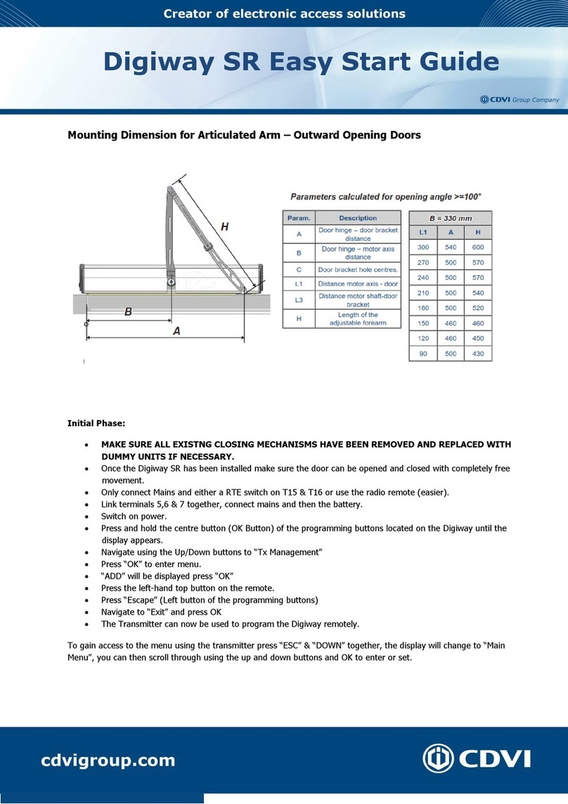
6) Secure the articulated arm bracket to the door reffering to distance A of the table6) Secure the articulated arm bracket to the door reffering to distance A of the table
above;above;
7) Attach the articulated arm to the drive shaft using the M6 xing bolt provided;7) Attach the articulated arm to the drive shaft using the M6 xing bolt provided;
8) If distance L3 is larger (see above) an optional extension shaft can be used,8) If distance L3 is larger (see above) an optional extension shaft can be used,
available in 30mm, 55mm and 80mm;available in 30mm, 55mm and 80mm;
9) Optional extension shaft: Fix the arm to the drive shaft using the M6 bolt provided9) Optional extension shaft: Fix the arm to the drive shaft using the M6 bolt provided
with the extension;with the extension;
10) Check full free movement whilst in free mode;10) Check full free movement whilst in free mode;
11) Make all electrical connections;11) Make all electrical connections;
12) Apply power;12) Apply power;
13)13) Follow the “Getting Started” procedureFollow the “Getting Started” procedure;;
14) Connect the Ground wire to the cover terminal and x the cover.14) Connect the Ground wire to the cover terminal and x the cover.
Connect the equipment to the Mains power using the appropriate cable (3 x 1,5mmConnect the equipment to the Mains power using the appropriate cable (3 x 1,5mm22),),
passing it through the rear opening of the prole and the backplate and avoiding being passing it through the rear opening of the prole and the backplate and avoiding being
too tight and touching sharp edges. At the end of the installation, connect the groundtoo tight and touching sharp edges. At the end of the installation, connect the ground
(earth) cable provided from the control PCB to the push on connector on the cover.(earth) cable provided from the control PCB to the push on connector on the cover.
Parameter Speed Power Description
(mm) (mm)
AA410410 430430 Door hinge – door bracket distanceDoor hinge – door bracket distance
BB270270 360360 Door hinge – motor axis distanceDoor hinge – motor axis distance
A - BA - B 140140 7070 Motor axis – door bracket distanceMotor axis – door bracket distance
CC4040 Bracket holes distanceBracket holes distance
L1L1 55 - 19555 - 195 Door jamb widthDoor jamb width
L2L2 371371 Distance wall - articulationDistance wall - articulation
L3L3 4343 Distance motor shaft-door bracketDistance motor shaft-door bracket

EN EN
DIGIWAY Plus
Inward or Outward Door Operator
14
Electronic PCB Controller Layout and Push ButtonsElectronic PCB Controller Layout and Push Buttons
Display LCDDisplay LCD
BatteryBattery
connectorconnector FuseFuse
3,15A3,15A
PEPE
ConnectionConnection
Monitor LED’sMonitor LED’s
19-way19-way
terminal blockterminal block
7-way7-way
terminal blockterminal block
SerialSerial
connectorconnector
FuseFuse
1A1A
ESC - back to upper levelESC - back to upper level
scroll UP / increases valuescroll UP / increases value
scroll DOWN / decreases valuescroll DOWN / decreases value
OKOK
Not UsedNot Used
External switchExternal switch
I 0 III 0 II
DOOR ALWAYSDOOR ALWAYS
OPENOPEN
DOOR FREE*DOOR FREE*
FULLY AUTOMATICFULLY AUTOMATIC
Wiring diagramWiring diagram
RCD residual-RCD residual-
current circuitcurrent circuit
breakerbreaker
3 pos. switch3 pos. switch
autom / door freeautom / door free
/ always open/ always open
NIght / DayNIght / Day
Start/StopStart/Stop
Door openDoor open
relayrelay
Fire-alarmFire-alarm
VoltageVoltage
ElectrolockElectrolock
FTC-S [ Stop ]FTC-S [ Stop ]
FTC [ Re-open ]FTC [ Re-open ]
InternalInternal
RadarRadar
ExternalExternal
RadarRadar
3 x 1,5 mm3 x 1,5 mm22
3 x 0.8 mm3 x 0.8 mm22
2 x 0.8 mm2 x 0.8 mm22
4 x 0.25 mm4 x 0.25 mm22
6 x 0.8 mm6 x 0.8 mm22
* System Off* System Off

EN EN DIGIWAY Plus
Inward or Outward Door Operator
15
Jumper for external switch exclusionJumper for external switch exclusion
The external mode switch on the end cap can be isolated to prevent misuse or for useThe external mode switch on the end cap can be isolated to prevent misuse or for use
with a remote switching device such as the DWSP-KS keyswitch.with a remote switching device such as the DWSP-KS keyswitch.
SwitchSwitch
excludedexcluded
JUMPER OFFJUMPER OFF
SwitchSwitch
enabledenabled
JUMPER ONJUMPER ON
Electrical connectionsElectrical connections
BatteryBattery
++--
FUSE 5AFUSE 5A
to toroidalto toroidal
transformertransformer
to the motorto the motor
Door OpenDoor Open
Relay OutputRelay Output
INPUT FireINPUT Fire
voltagevoltage
FTC-S (*)FTC-S (*)
FTC (*)FTC (*)
AutomaticAutomatic
Door freeDoor free
Door openDoor open
RADAR Int.RADAR Int.
RADAR Ext.RADAR Ext.
Day/NightDay/Night
Open/Close Trigger I/POpen/Close Trigger I/P
MagnetMagnet
ExternalExternal
magnetmagnet
supplysupply
Supply radarsSupply radars
& photocells& photocells
ElectrolockElectrolock
SupplySupply
Electrolock relayElectrolock relay
from toroidal transformerfrom toroidal transformer
(*) See next page for full connection descriptions(*) See next page for full connection descriptions
NN
LL
PEPE
230 Vac230 Vac

EN EN
DIGIWAY Plus
Inward or Outward Door Operator
16
Connection detailConnection detail
19-way terminal block
1Output C Door Open Relay
2Output NO Door Open Relay
3Input V- Fire alarm voltage
4Input V+ Fire alarm voltage
5Safety Input NC Stop Photocells [FTC-S]
6Safety Input C Photocells
7Safety Input NC Re-open Photocells [FTC]
8Input NO switch pos. I
9Input C switch pos. 0
10 Input NO switch pos. II
11 Input NA Radar external
12 Input C Radar
13 Input NO Radar internal
14 Input NO Day/Night switch
15 Input common
16 Input NO push-button open/close/stop
T1 Output (+12) Test FTC-S
CCommon test photocells ( GND)
T2 Output (+12) Test FTC
7-way terminal block
17 Output NO relay electrolock
18 Output C relay electrolock
19 Output NC relay electrolock
20 Output 0V external devices power
21 Output 13,5 Vdc external devices power
22 Output 0V electrolock power
23 Output 12 Vdc electrolock power
2-way terminal block
24 Input Line 230 Vac
25 Input Neutral 230 Vac
2-way terminal block
26 Output 230 Vac to internal toroidal transformer
27 Output 230 Vac to internal toroidal transformer
2-way terminal block
28 Input Motor BLACK cable
29 Input Motor RED cable
2-way terminal block
30 Input from internal toroidal transformer
31 Input from internal toroidal transformer
Door open relay
Door Status Closed Opening/Open/Closing
Relay OFF ON
Monitored photocells wiringMonitored photocells wiring
The Standard EN16005 indicates that the parts of the system which have a direct effectThe Standard EN16005 indicates that the parts of the system which have a direct effect
on safety must comply with EN12978 and be designed to comply with EN ISO 13849-1on safety must comply with EN12978 and be designed to comply with EN ISO 13849-1
Performance Level “C”. Safety related parts of the control system used for escape routePerformance Level “C”. Safety related parts of the control system used for escape route
functionality shall comply with EN ISO 13849-1 Performance Level “D”.functionality shall comply with EN ISO 13849-1 Performance Level “D”.
If devices type ESPE (photocells) are used, they must be monitored by the drive system.If devices type ESPE (photocells) are used, they must be monitored by the drive system.
DIGIWAY Plus is equipped with output test signals (Test1, C, Test2) that check theDIGIWAY Plus is equipped with output test signals (Test1, C, Test2) that check the
photocells’ status before any motion. The system switches the photocell off and backphotocells’ status before any motion. The system switches the photocell off and back
on within a few mS to detect a change of the safety signal on terminals 5-6 and 6-7.on within a few mS to detect a change of the safety signal on terminals 5-6 and 6-7.
If the signal change is regular, door motion is enabled, otherwise the motion is stoppedIf the signal change is regular, door motion is enabled, otherwise the motion is stopped
or enabled in low energy mode (see the Advance Options menu).or enabled in low energy mode (see the Advance Options menu).

EN EN DIGIWAY Plus
Inward or Outward Door Operator
17
5 6 75 6 7 T1 C T2T1 C T2 20 2120 21
Power (+)Power (+)
Power (-)Power (-)
Relay CRelay C
RelayRelay NCNC
Test Input (-)Test Input (-)
Test Input (+)Test Input (+)
STOP Photocells (FTC-S)STOP Photocells (FTC-S)
REOPEN photocells (FTC)REOPEN photocells (FTC)
LOW ENERGY modeLOW ENERGY mode
The Standard EN 16005 (Annex F) indicates the parameters for Low Energy mode: the minimumThe Standard EN 16005 (Annex F) indicates the parameters for Low Energy mode: the minimum
open / close time from 10° to 90° is indicated in the following table:open / close time from 10° to 90° is indicated in the following table:
Width ofWidth of
doorset leafdoorset leaf
(m)(m)
Mass (Kg)
50 60 70 80 90
Time (sec.)
0,750,75 3,03,0 3,23,2 3,23,2 3,33,3 3,53,5
0,850,85 3,13,1 3,13,1 3,23,2 3,43,4 3,63,6
1.001.00 3,23,2 3,43,4 3,73,7 4,04,0 4,24,2
1.21.2 3,83,8 4,24,2 4,54,5 4,84,8 5,15,1
For other widths and/or masses the times can be calculated using the formula:For other widths and/or masses the times can be calculated using the formula:
See theSee the ADVANCED SETTINGSADVANCED SETTINGS Menu to set the door-set leaf dimensions and operating mode inMenu to set the door-set leaf dimensions and operating mode in
case of photocell malfunction.case of photocell malfunction.
5 6 75 6 7 T1 C T2T1 C T2 20 2120 21
Power (+)Power (+)
Power (-)Power (-)
Relay CRelay C
RelayRelay NCNC
Test Input (-)Test Input (-)
Test Input (+)Test Input (+)
where t = time in sec.,where t = time in sec.,
D = diameter doorset leaf in meters,D = diameter doorset leaf in meters,
m = mass in kg.m = mass in kg.

EN EN
DIGIWAY Plus
Inward or Outward Door Operator
18
Meaning of LP LED messagesMeaning of LP LED messages
FunctionFunction
LED GREEN LED ORANGE LED RED
ONON blinkingblinking ONON blinkingblinking ONON blinkingblinking fastfast
blinkingblinking
Everything OKEverything OK OO
Battery operatedBattery operated OO
Fire alarmFire alarm O (fast)O (fast)
Night ModeNight Mode OO
Night Mode &Night Mode &
battery operatedbattery operated OO
Door freeDoor free --------------
Current calculationCurrent calculation
in progressin progress OO
SelearningSelearning red/red/
greengreen
Battery testBattery test OO
Battery dischargedBattery discharged OO
Safety photocellsSafety photocells
malfunctionmalfunction OO
Service requiredService required OO
(slow)(slow)
Electronic card LED’sElectronic card LED’s
LED ON LED OFF
L1 Fire voltage OK Fire voltage ABSENT
L2 NC contact stop photocells closed NC contact stop photocells open
L3 NC contact re-open photocells closed NC contact re-open photocells open
L4 Automatic mode -
L5 Door always open -
L6 External radar active -
L7 Internal radar active -
L8 Night mode Day mode
L9 Open/close command active -
BatteryBattery
Main features:Main features:
Voltage : 12VVoltage : 12V
Rated charge : 1,3AhRated charge : 1,3Ah
Autonomy in battery operating mode(*) : 270 cycles / 16 hoursAutonomy in battery operating mode(*) : 270 cycles / 16 hours
Average charge and discharge cycles : 800Average charge and discharge cycles : 800
Average battery life : 2-3 years [in rated operating temperature]Average battery life : 2-3 years [in rated operating temperature]
Cycles with battery at end-of-life : 100Cycles with battery at end-of-life : 100
(*): In case of mains power failure (230vac) the operator functions in battery mode. The(*): In case of mains power failure (230vac) the operator functions in battery mode. The
autonomy declared above depends on the number of external devices connected i.e. radar,autonomy declared above depends on the number of external devices connected i.e. radar,
photocells etc.photocells etc. The internal softwareThe internal software periodicallyperiodically executes a test on the battery charge. (Ledexecutes a test on the battery charge. (Led
LP blinks RED QUICKLY). If, at the end of the test, the battery is discharged and the LP doesn’tLP blinks RED QUICKLY). If, at the end of the test, the battery is discharged and the LP doesn’t
stop blinking RED, replace the battery with an equivalent.stop blinking RED, replace the battery with an equivalent.

EN EN DIGIWAY Plus
Inward or Outward Door Operator
19
GETTING STARTEDGETTING STARTED
DIGIWAY Plus is equipped with a 2x16 characters LCD Display and by a 5-key keyboard.DIGIWAY Plus is equipped with a 2x16 characters LCD Display and by a 5-key keyboard.
The operating conguration can be set navigating through several menus. The menu The operating conguration can be set navigating through several menus. The menu
has a tree structure with a main menu and different sub-menus.has a tree structure with a main menu and different sub-menus.
ACCESS to the MAIN MENUACCESS to the MAIN MENU
C + DC + D
OKOK for 4 secfor 4 sec
AABB
CCDD
OROR
Main Menu
Door Calibration
Main Menu
TX management
Main Menu
Service Main Menu
Information
Main Menu
Advanced Settings
Main Menu
Languages Main Menu
Main Functions
Main Menu
Configuration
Main Menu
Exit
Main Menu
System Reset
Main Menu
Factory Defaults
3] SYSTEM CONFIGURATION AND SETTINGS3] SYSTEM CONFIGURATION AND SETTINGS
Guided congurationGuided conguration
The operator is supplied with a 4-button transmitter. On completion of theThe operator is supplied with a 4-button transmitter. On completion of the
mechanical xing and the electric connections, proceed with the memorisation mechanical xing and the electric connections, proceed with the memorisation
of the transmitter into the internal DIGIWAY memory. This transmitter can thenof the transmitter into the internal DIGIWAY memory. This transmitter can then
be used to set up all parameters, without having to access the 5 buttons onboard.be used to set up all parameters, without having to access the 5 buttons onboard.
Important:Important: Do not issue this transmitter to the end user as programming or factoryDo not issue this transmitter to the end user as programming or factory
defaults could be applied without realising. Any other transmitter added after this onedefaults could be applied without realising. Any other transmitter added after this one
will trigger the operation only.will trigger the operation only.
The transmitter keys correspond to the onboard push-button according to the nextThe transmitter keys correspond to the onboard push-button according to the next
diagram:diagram:
ESCESC
DOWNDOWN
UPUP UPUP
DOWNDOWN
ESCESC

EN EN
DIGIWAY Plus
Inward or Outward Door Operator
20
The set-up of the operator can be divided into 5 stepsThe set-up of the operator can be divided into 5 steps::
•• STEP I : INITIAL SETUPSTEP I : INITIAL SETUP (preliminary actions)(preliminary actions)
•• STEP II : CONFIGURATIONSTEP II : CONFIGURATION (set-up of the basic operating mode)(set-up of the basic operating mode)
•• STEPSTEP III : DOOR CALIBRATIONIII : DOOR CALIBRATION (automatic detection of the door(automatic detection of the door
characteristics)characteristics)
•• STEPSTEP IV : ADJUSTMENTSIV : ADJUSTMENTS (further adjustments and personalisation)(further adjustments and personalisation)
•• STEPSTEP V : SPECIAL PARAMETERSV : SPECIAL PARAMETERS ((set-up of theset-up of the advanced parameters)advanced parameters)
STEP I: INITIAL SETUP
Press and hold the OK button of the keyboard until the display enters the mainPress and hold the OK button of the keyboard until the display enters the main
menu.menu.
Select the language by scrolling through list using the UP and Down buttons.Select the language by scrolling through list using the UP and Down buttons.
Press OK to conrm: the display shows the message OK and then displays all Press OK to conrm: the display shows the message OK and then displays all
messages in the new languagemessages in the new language
Exit from the menu with the button ESC.Exit from the menu with the button ESC.
Scroll through the main menu, select TX MANAGEMENT submenu and press OKScroll through the main menu, select TX MANAGEMENT submenu and press OK
Select the option ADD TX and press OKSelect the option ADD TX and press OK
Press the transmitter key OK (top-left button): the display will show the S/N,Press the transmitter key OK (top-left button): the display will show the S/N,
conrming the memorisation conrming the memorisation
Exit from the menu by pressing the ESC button.Exit from the menu by pressing the ESC button.
Exit from the main menu selecting EXIT MENU.Exit from the main menu selecting EXIT MENU.
2
1
3
4
5
6
7
8
9
From this time on the remote control is enabled to access the main menu. Enter simplyFrom this time on the remote control is enabled to access the main menu. Enter simply
by pressing simultaneously keysby pressing simultaneously keys ESC + DOWNESC + DOWN..
NOTE: ONLY THE FIRST TRANSMITTER MEMORISED CAN ACCESS THE MAINNOTE: ONLY THE FIRST TRANSMITTER MEMORISED CAN ACCESS THE MAIN
MENU! All the next added transmitters can only open the door! It is advisableMENU! All the next added transmitters can only open the door! It is advisable
not to give the rst remote to the end user for general use.not to give the rst remote to the end user for general use.
The OK key of the tranmitter has multiple functions: accept/save in the menu andThe OK key of the tranmitter has multiple functions: accept/save in the menu and
Start/Stop in normal operation.Start/Stop in normal operation.
Other manuals for DIGIWAY PLUS
2
Table of contents
Other CDVI Door Opening System manuals
Popular Door Opening System manuals by other brands

Assa Abloy
Assa Abloy Norton 9510 Series installation instructions

Von Duprin
Von Duprin 98/9975 Series installation instructions

PortaPivot
PortaPivot StealthPivot instruction manual

Roger Technology
Roger Technology R41 Series Instructions and Recommendations

Daihatsu
Daihatsu EDM18ZII instruction manual

Aprimatic
Aprimatic Over Installation and maintenance manual