CDVI DIGIWAY PLUS User manual

Fully automated operator for inward or outward
opening doors
DIGIWAY PLUS
EN
WARRANTY
YEAR
2

EN EN
2 3
DIGIWAY PLUS
Fully automated operator for inward or outward opening doors DIGIWAY PLUS
Fully automated operator for inward or outward opening doors
!
IMPORTANT SAFETY INSTRUCTIONSIMPORTANT SAFETY INSTRUCTIONS
This manual is intended for professional installers, who have received appropriate training.
Installation and connections must be carried out in accordance with Good Working Practice
and in compliance with the current Regulations. Poor installation could cause a health & safety
hazard.
Read this manual carefully before starting the installation process.Read this manual carefully before starting the installation process.
First check all of the existing door and frame structure - verify its integrity, stability and strength.
If necessary modify the structure in order to make it standard, being aware of all the possible
problems that could occur during normal use.
Verify that all the zones where there is a risk of crushing, dragging, shearing and other dangers
are protected by electronic safety devices, safety boards, or barriers.
This can be achieved if the distance does not exceed 8 mm. However, to avoid entrapment for
the various parts of the body, the following distances are considered sufcient:
Fingers > 25mm
Foot > 50mm
Head > 300mm
Body > 500mm
The forces produced by the complete system must comply with the current standards and,
where this is not possible, protect the zones with electronic safety devices.
Apply hazardous area notices required by the applicable regulations. Before the actuator is
connected, make sure that the plate details correspond to those of the mains power and that
there is a differential circuit-breaker and adequate protection against overcurrents on the supply
side of the system.
Fit a Dual Pole disconnection switch with contact opening gap of at least of 3 mm.
Interrupt the power supply before opening the cover of the actuator for any maintenance or
repair intervention.
Handling of electronic parts must be carried out wearing grounded antistatic bracelets to avoid
any static damage.
Servicing the actuator is of fundamental importance if the system is to operate correctly and
safely.
Comply with the manufacturer’s instructions described in this manual.
Only use genuine spare parts if replacements or repairs are required. The motor manufacturer
declines any responsibility if component parts tted are not compatible with safe and correct
operation. The actuator must be installed inside only.
GENERAL SAFETY INSTRUCTIONS AND PRECAUTIONSGENERAL SAFETY INSTRUCTIONS AND PRECAUTIONS......................................................................................................................................33
.............. Machinery DirectiveMachinery Directive......................................................................................................................................................................................................................44
.............. Declaration of the ManufacturerDeclaration of the Manufacturer....................................................................................................................................................................................55
1] IDENTIFYING PRODUCT AND PARTS1] IDENTIFYING PRODUCT AND PARTS................................................................................................................................................................................66
.............. AccessoriesAccessories............................................................................................................................................................................................................................................77
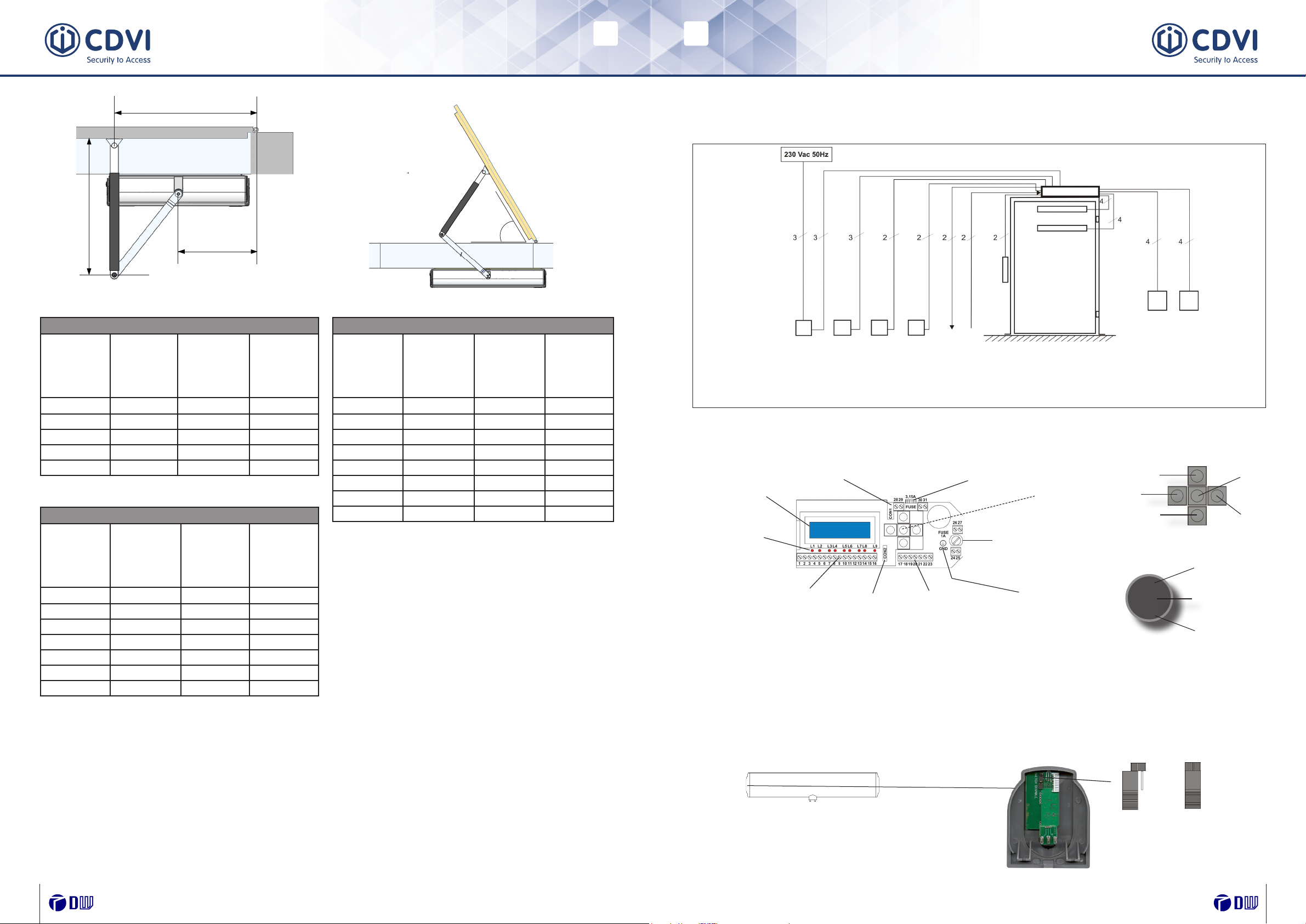
.............. Mounting diagram .......................................................................................Mounting diagram .................................................................................................................................88
.............. Technical specicationsTechnical specications ............................................................................................................................................................................................................99
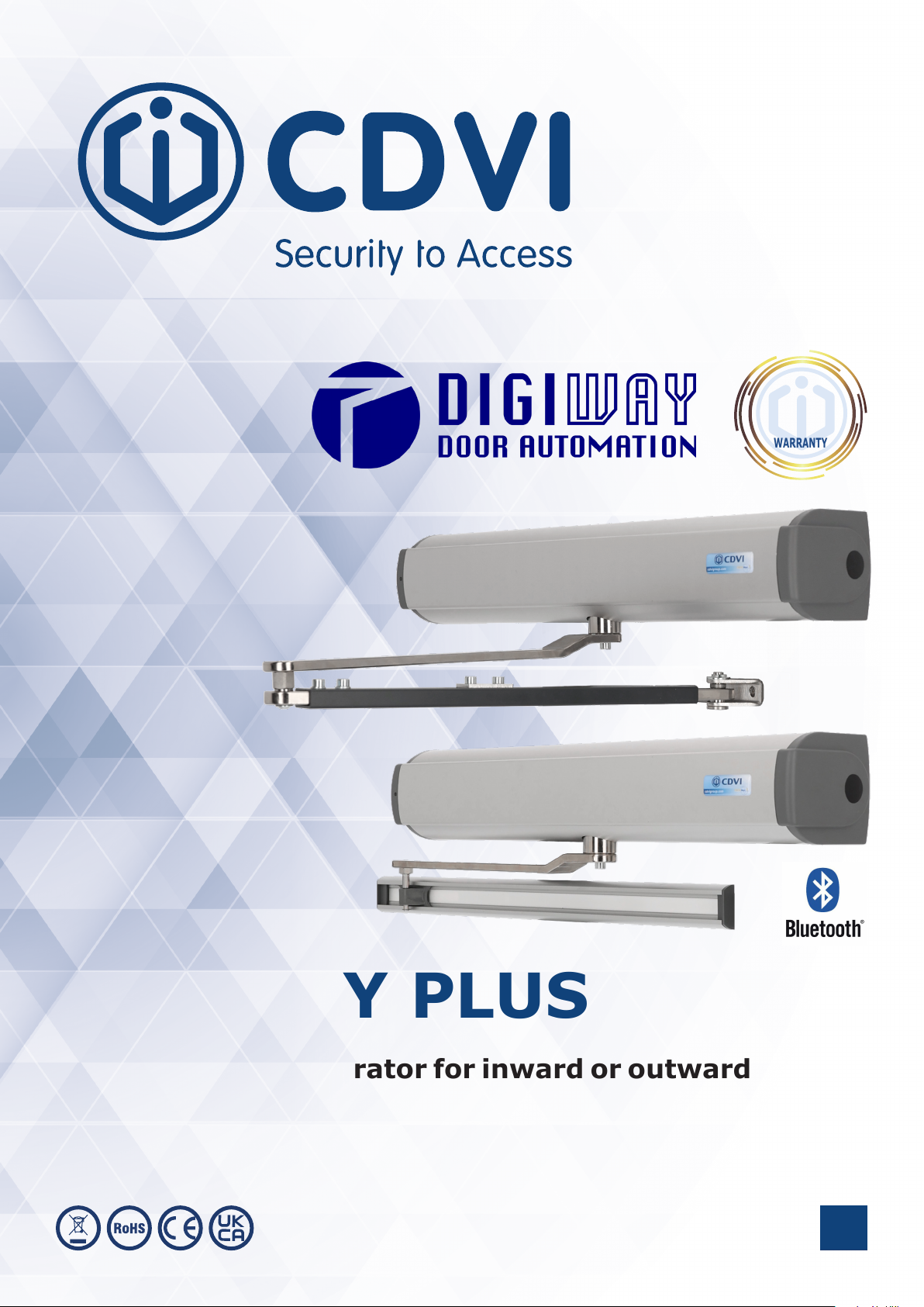
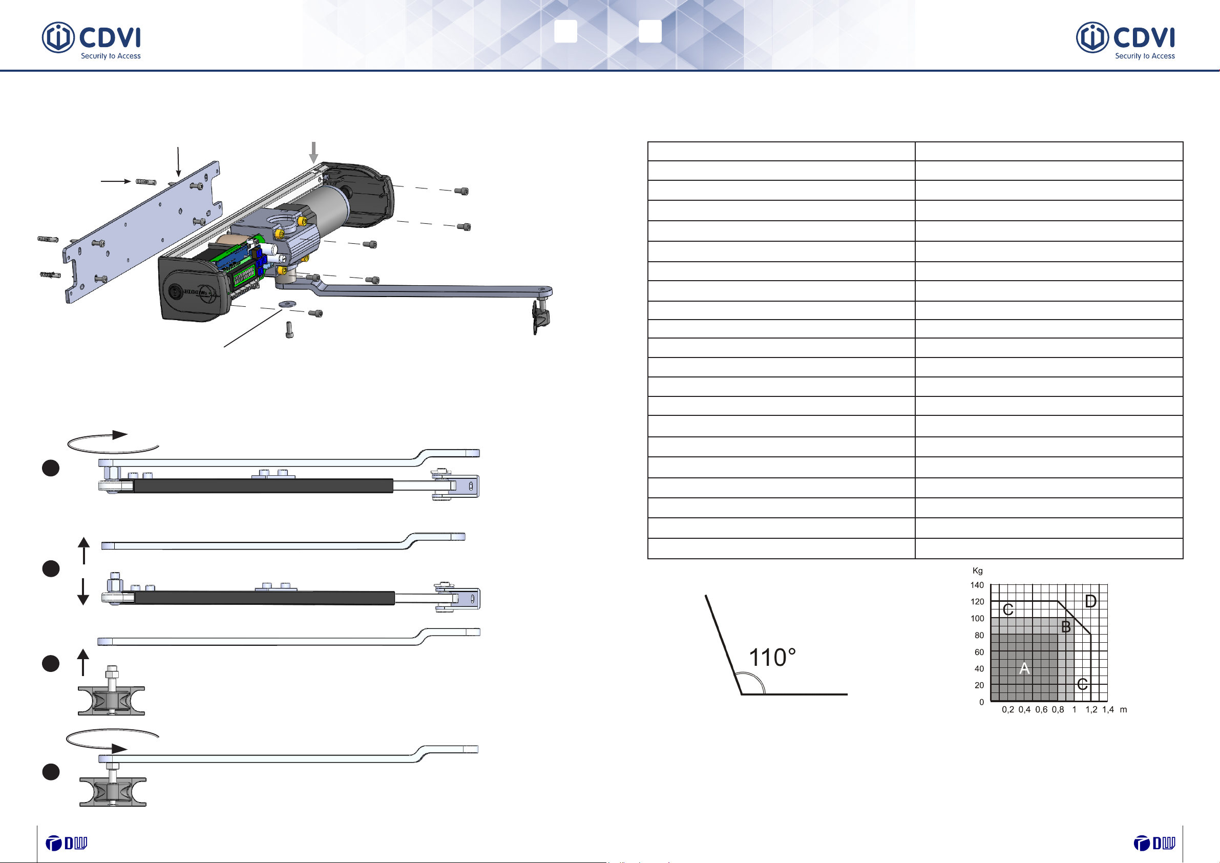
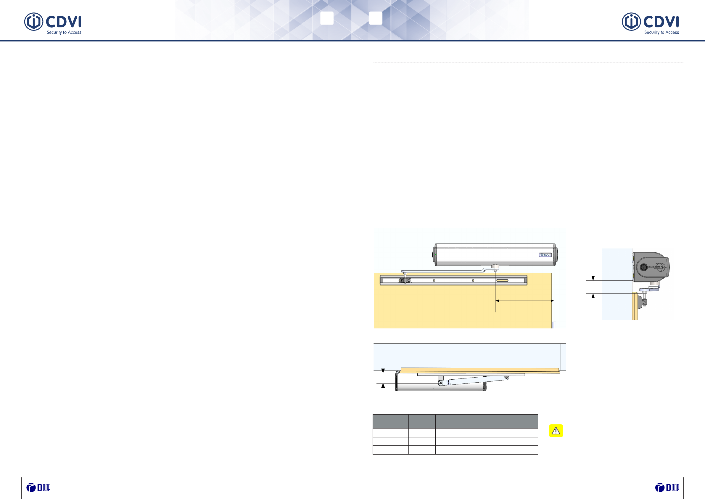
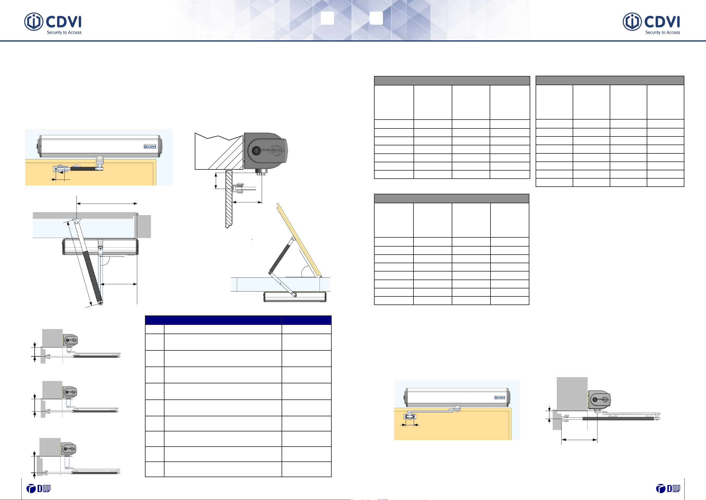
2] INSTALLATION2] INSTALLATION ......................................................................................................................................................................................................................................1111
.............. Mechanical installation: Sliding arm versiont Mechanical installation: Sliding arm versiont ............................................................................................................................................1111
.............. Mechanical installation: Articulated arm version Mechanical installation: Articulated arm version ..................................................................................................................................1212
.............. Wiring diagramWiring diagram..............................................................................................................................................................................................................................1515
.............. Electrical connectionsElectrical connections ............................................................................................................................................................................................................1616
.............. Monitored photocells wiringMonitored photocells wiring............................................................................................................................................................................................1717
.............. LED messagesLED messages................................................................................................................................................................................................................................1818
.............. BatteryBattery....................................................................................................................................................................................................................................................1919
3] SYSTEM CONFIGURATIONS AND SETTINGS3] SYSTEM CONFIGURATIONS AND SETTINGS........................................................................................................................................................1919
.............. Language selectionLanguage selection ..................................................................................................................................................................................................................1919
.............. Master transmitter memorisationMaster transmitter memorisation ............................................................................................................................................................................1919
.............. Wizard setupWizard setup....................................................................................................................................................................................................................................2121
.............. Part I : CongurationPart I : Conguration..............................................................................................................................................................................................................2222
.............. Part IIPart II : Door calibration : Door calibration ....................................................................................................................................................................................................2323
.............. Part III : Main FunctionsPart III : Main Functions ....................................................................................................................................................................................................2525
.............. Part IVPart IV : Door calibration: Additional features : Door calibration: Additional features ..........................................................................................................................................2323
.............. Part V : Advanced settingsPart V : Advanced settings ..............................................................................................................................................................................................2727
.............. Disabled persons settingsDisabled persons settings ................................................................................................................................................................................................3232
.............. Remote controls managementRemote controls management ....................................................................................................................................................................................3333
.............. Menu serviceMenu service....................................................................................................................................................................................................................................3434
.............. Reset to factory defaults & system resetReset to factory defaults & system reset ........................................................................................................................................................3636
4]4] DOUBLE DOOR CONFIGURATIONDOUBLE DOOR CONFIGURATION ....................................................................................................................................................................................3737
5]5] INSTRUCTIONS FOR USEINSTRUCTIONS FOR USE..........................................................................................................................................................................................................4242
6]6] MAINTENANCEMAINTENANCE......................................................................................................................................................................................................................................4343
7] BLUETOOTH CONNECTION & MANAGEMENT7] BLUETOOTH CONNECTION & MANAGEMENT......................................................................................................................................................4444
Table of Contents pageTable of Contents page
The present document contains important precautions for safe use and operation.The present document contains important precautions for safe use and operation.
Read the instructions carefully before commencing the installation. Keep thisRead the instructions carefully before commencing the installation. Keep this
document even after installation.document even after installation.

EN EN
4 5
DIGIWAY PLUS
Fully automated operator for inward or outward opening doors DIGIWAY PLUS
Fully automated operator for inward or outward opening doors
The manufacturer declines all liability for damage caused by outdoor assembly without adequate
protection.
This product cannot be installed in places with an explosive atmosphere or in the presence of
ammable fumes or gases.
The appliance can be used by children aged 8 or under and by persons with reduced physical,
sensory or mental abilities, without experience or prior knowledge, provided they are under
surveillance or after they have received instructions concerning safe use of the appliance and
an understanding of the dangers inherent to it.
The sound pressure level, weighted A, of the noise emitted by the device is less than 70 dB
(A).
If a passive emergency button is installed, it must be installed in view of the door but away
from moving parts.
Unless this is protected by a security key, it must be installed at a minimum height of 1.5 m and
not accessible to the public.
Children must not play with the appliance. Cleaning and maintenance intended for use by the
user must not be carried out by children without supervision.
Automatic pedestrian doors fall into the application eld of the Machinery Directive (2006/42/
CE).
This states that the installer who motorizes a door becomes the manufacturer of machinery
and so must:
1. Prepare the Technical Construction File (which must contain the documents indicated
in Annex V of the Machinery Directive) and must be kept and placed at the disposal of
competent national authorities for at least ten years from the date of manufacture of the
motorised door.
2. Draft the EC Declaration of Conformity in accordance with Annex II-A of the Machinery
Directive.
3. Apposer le marquage CE sur la porte motorisée en accord avec les points 1.7.3 de l’annexe
I de la Directive Machine.
The installer must consign to the customer the following documents:
1. Instructions on how to operate and safely use the system;
2. Routine maintenance instructions;
3. Declaration of conformity;
4. Maintenance register.
vvvvvvvv
Declaration of the ManufacturerDeclaration of the Manufacturer
(According to Directive(According to Directive 2006/42/CE2006/42/CE Annex II part B)Annex II part B)
The ManufacturerThe Manufacturer CDVI WIRELESS SPA - CDVI GroupCDVI WIRELESS SPA - CDVI Group
Via Piave,23Via Piave,23
31020 S.Pietro di Feletto (TV)31020 S.Pietro di Feletto (TV)
ITALYITALY
Herewith declares that the automatic operator for swing doorsHerewith declares that the automatic operator for swing doors
Brand : DIGIWAYBrand : DIGIWAY
Model : DIGIWAY PLUS Model : DIGIWAY PLUS
Types : DWPS102XX, DWDP102XXTypes : DWPS102XX, DWDP102XX
- constitutes a “partly completed machinery” and it is intended to be incorpored- constitutes a “partly completed machinery” and it is intended to be incorpored
into machinery or to be assembled with other machinery to constitute ainto machinery or to be assembled with other machinery to constitute a
machinery covered by Directive 2006/42/CE; machinery covered by Directive 2006/42/CE;
- complies with the following Directives: - complies with the following Directives:
2006/95/CE ( Low Voltage Directive )2006/95/CE ( Low Voltage Directive )
2004/108/CE ( Electromagnetic Compatibility Directive )2004/108/CE ( Electromagnetic Compatibility Directive )
2014/53/UE ( RED )2014/53/UE ( RED )
European Standard EN16005 : Power Operated doorsets - Safety in UseEuropean Standard EN16005 : Power Operated doorsets - Safety in Use
- it is not allowed to put the machinery into service until the machinery into- it is not allowed to put the machinery into service until the machinery into
which it has to be incorporated or of which it has to be a component has beenwhich it has to be incorporated or of which it has to be a component has been
found and declarated to be in compliance with the provisions of the Directivefound and declarated to be in compliance with the provisions of the Directive
2006/42/CE. 2006/42/CE.
S.Pietro di Feletto,S.Pietro di Feletto, 01/11/201701/11/2017
G. Massimo Dalle CarbonareG. Massimo Dalle Carbonare
( Product manager )( Product manager )
Machinery Directive
Introduction
The DIGIWAY operator type DWPS102XX, DWPD102XX belongs to the Service Class 5 (600
cycles a day for 5 years min).
Applications: HEAVY DUTY, for pedestrian accesses to institutional complexes with very intense
use.

EN EN
6 7
DIGIWAY PLUS
Fully automated operator for inward or outward opening doors DIGIWAY PLUS
Fully automated operator for inward or outward opening doors
7 8 9
56
3
12
4
11
10
12 13 15
14
Description P/N F-code
Articulated
arm short tube
extenstion DWAA35 F0543000217
ArticulatedArticulated
arm long tubearm long tube
extenstionextenstion DWAA55 F0543000218
Tube extensionTube extension
onlyonly DWAA55E F0543000219
Universal arm kitUniversal arm kit DWSRKU F0543000122
Extension shaftExtension shaft
55 mm55 mm DWSE F0543000033
Extension shaftExtension shaft
30 mm30 mm DWSE30 F0543000123
Extension shaftExtension shaft
80 mm80 mm DWSE80 F0543000136
Double doorDouble door
cablecable DWPCS F0543000124
Mounting toolsMounting tools
kitkit DWTK F0543000156
Bluetooth plug-inBluetooth plug-in
module (*)module (*) DWMBT F0543000179
DIGIWAY type DWPx102xx is an indoor operator for swing doors, with integrated electronic
controller and radio receiver. The opening and closing motion is electromechanical with backup
battery, which assures operation in cases of power failure.
The following versions are available:
LegendLegend
1 - Anodised aluminium cover1 - Anodised aluminium cover
2 - Motor shaft2 - Motor shaft
3 - Status led LP3 - Status led LP
4 - Receiver card4 - Receiver card
5 - Display LCD5 - Display LCD
6 - 5-button keyboard6 - 5-button keyboard
7 - Gear box7 - Gear box
8 - Motoriductor8 - Motoriductor
9 - Encoder9 - Encoder
10 - Slot for cover opening10 - Slot for cover opening
11 - Toroidal transformer11 - Toroidal transformer
12 - Backup battery12 - Backup battery
13 - Battery cable with13 - Battery cable with
protection fuseprotection fuse
14 - Jumper for external14 - Jumper for external
selector exclusionselector exclusion
15 - Operating mode15 - Operating mode
selectorselector
Accessories
Code F Reference Description
F0543000093F0543000093 DWPS102SCD DIGIWAY PLUS operator 230VAC for inswing doors - sliding armDIGIWAY PLUS operator 230VAC for inswing doors - sliding arm
F0543000094F0543000094 DWPS102ACD DIGIWAY PLUS operator 230VAC for outswing doors - articulated armDIGIWAY PLUS operator 230VAC for outswing doors - articulated arm
F0543000095 DWPS102UCD DIGIWAY PLUS operator 230VAC for inswing or outswing doors - universalDIGIWAY PLUS operator 230VAC for inswing or outswing doors - universal
armarm
F0543000180 DWPS102ABT DIGIWAY PLUS operator 230VAC for inswing doors - articulated arm
w/ Bluetooth module
F0543000181 DWPS102SBT DIGIWAY PLUS operator 230VAC for outswing doors - sliding arm
w/ Bluetooth module
F0543000182 DWPS102UBT DIGIWAY PLUS operator 230VAC for inswing or outswing doors - universal
arm - w/ Bluetooth module
The operator is suitable for swing doors with max width of 1.2 m or max weight of 120kg
(refer to diagram on page 7). At max speed the door can open and close within 3 sec. (90°),
depending on door weight and dimensions.
See the technical specications in the following pages of this manual.
Warning:Warning: The operator is suitable only for top-jamb xing. Door leaf The operator is suitable only for top-jamb xing. Door leaf
xing is not allowed.xing is not allowed.
1] IDENTIFYING THE PRODUCT AND ITS PARTS
(*): The models with the sufx BT (refer to table on pg 6), come with the Bluetooth module built-in. The (*): The models with the sufx BT (refer to table on pg 6), come with the Bluetooth module built-in. The
models with the sufx CD on the part name can also be equipped with the Bluetooth module. See page models with the sufx CD on the part name can also be equipped with the Bluetooth module. See page
43 for details concerning after-sale installation of the module, for its conguration and use.43 for details concerning after-sale installation of the module, for its conguration and use.

EN EN
8 9
DIGIWAY PLUS
Fully automated operator for inward or outward opening doors DIGIWAY PLUS
Fully automated operator for inward or outward opening doors
I
II
III
IV
Mounting diagram Technical specications
Use conditionsUse conditions
Zone A : Very intense use : 600 cycles / dayZone A : Very intense use : 600 cycles / day
Zone B : Intense use : 200-300 cycles / dayZone B : Intense use : 200-300 cycles / day
Zone C : Use at reduced speedZone C : Use at reduced speed
Zone D : Not allowedZone D : Not allowed
Cover lift pointCover lift point
Angle d’ouverture maximal de la porteAngle d’ouverture maximal de la porte
M6x14M6x14
M6x14M6x14
M6x14M6x14
Plugs SX 8
Screws for plugs SX 8Screws for plugs SX 8
WasherWasher
Universal arm: articulated arm into sliding arm conversion
Turn clockwise with a 15 mm spannerTurn clockwise with a 15 mm spanner
Turn anti-clockwise with a 13 mm spannerTurn anti-clockwise with a 13 mm spanner
Replace with sliding blockReplace with sliding block
General featuresGeneral features
Power supplyPower supply 230 Vac - 50 Hz230 Vac - 50 Hz
Motor torqueMotor torque 15 Nm15 Nm
Max powerMax power 50 W50 W
Operating classOperating class 5 (5 (heavy dutyheavy duty))
BatteryBattery 12 Vdc 1,3 Ah12 Vdc 1,3 Ah
Overall dimensionsOverall dimensions 511 x 90 x 110 mm511 x 90 x 110 mm
WeightWeight 5kg5kg
Operating temperatureOperating temperature -10°C ÷ +55°C-10°C ÷ +55°C
IP GradeIP Grade IP40IP40
Opening / closing timeOpening / closing time 3 ÷ 15 sec.3 ÷ 15 sec.
Pause timePause time 3 ÷ 90 sec.3 ÷ 90 sec.
Power for auxiliary devicesPower for auxiliary devices 13.5 Vdc / 500 mA [max]13.5 Vdc / 500 mA [max]
Power for electrolockPower for electrolock 12 Vdc / 1A [max]12 Vdc / 1A [max]
Electrolock output relayElectrolock output relay (C-NO-NC) 10A / 12V(C-NO-NC) 10A / 12V
Open door output relayOpen door output relay (C-NO) - 24 VA(C-NO) - 24 VA
Electrolock hold timeElectrolock hold time RéglableRéglable [0.1 sec. ÷ 5 min][0.1 sec. ÷ 5 min]
Power failure autonomyPower failure autonomy 270 cycles / 16 hours270 cycles / 16 hours
Transmitters security protocolTransmitters security protocol KeeLoq® Hopping CodeKeeLoq® Hopping Code
Receiver memoryReceiver memory 50 transmitters50 transmitters
Integrated receiver main specicationsIntegrated receiver main specications 433.92 MHz ASK / -107 dBm433.92 MHz ASK / -107 dBm
Fire voltage inputFire voltage input 24 ÷ 48 Vac/dc24 ÷ 48 Vac/dc
Largeur de la porte / poids de la porteLargeur de la porte / poids de la porte
PoidsPoids porteporte

EN EN
10 11
DIGIWAY PLUS
Fully automated operator for inward or outward opening doors DIGIWAY PLUS
Fully automated operator for inward or outward opening doors
A
B
C
2] INSTALLATION
Mechanical installation: sliding arm version
Important: Check the integrity of the door that is to be automated, veriying the Important: Check the integrity of the door that is to be automated, veriying the
operation in both directions is smooth without any friction from the closed to openoperation in both directions is smooth without any friction from the closed to open
position and the open to closed position. If this is not the case, make any repairsposition and the open to closed position. If this is not the case, make any repairs
or improvements necessary to achieve smooth operation of the door. Remove anyor improvements necessary to achieve smooth operation of the door. Remove any
manually operated locking mechanism unless it is to be used with a strike. A doormanually operated locking mechanism unless it is to be used with a strike. A door
stop is not required to complete the opening cycle.stop is not required to complete the opening cycle.
Warning:Warning: Any existing closing device should be removed to allow the door to move freely.Any existing closing device should be removed to allow the door to move freely.
Hydraulic devices MUST be replaced with dummy units as adjusting the device will not allowHydraulic devices MUST be replaced with dummy units as adjusting the device will not allow
the DIGIWAY to operate correctly.the DIGIWAY to operate correctly.
Main featuresMain features
Electronic card specicationsElectronic card specications
Operating modes: Automatic ( I ) - Door free ( 0 ) - Door always open (II)Operating modes: Automatic ( I ) - Door free ( 0 ) - Door always open (II)
Inputs: Re-open photocells (NC)Inputs: Re-open photocells (NC)
Stop photocells (NC)Stop photocells (NC)
Door always open (NO)Door always open (NO)
Door free (NO)Door free (NO)
External Radar (NO)External Radar (NO)
Internal Radar (NO)Internal Radar (NO)
Day / Night selection (NO) Day / Night selection (NO)
Open / Close command (NO) Open / Close command (NO)
Fire alarm voltage (+V, -V) [optoisolated] Fire alarm voltage (+V, -V) [optoisolated]
Outputs: Door open contact (C-NO)Outputs: Door open contact (C-NO)
External devices power 13.5 Vdc / 500 mA External devices power 13.5 Vdc / 500 mA
Electrolock output contacts (C-NO-NC)Electrolock output contacts (C-NO-NC)
Electrolock power 12 Vdc / 1 A Electrolock power 12 Vdc / 1 A
Test for safety devices (FTC- FTC-S)Test for safety devices (FTC- FTC-S)
Important:Important: The door faceThe door face
and DIGIWAY mounting mustand DIGIWAY mounting must
be in line as shown above.be in line as shown above.
The Sliding Arm is designed for pull applications and inward opening doors.The Sliding Arm is designed for pull applications and inward opening doors.
Thanks to the universal arm kit, the main lever of the articulated arm can also be used for a
sliding arm conguration.
•• Operating modes: Fully automatic, Door open, Door free/operation off;Operating modes: Fully automatic, Door open, Door free/operation off;
•• Operating with single door, double door, with or without leaf overlapping;Operating with single door, double door, with or without leaf overlapping;
•• Guided procedure for quick basic setup;Guided procedure for quick basic setup;
•• Adjustable motor torque during open and close phases;Adjustable motor torque during open and close phases;
•• Remote controls management, master transmitter and user transmitter;Remote controls management, master transmitter and user transmitter;
•• Auto slow down during approach to door limits;Auto slow down during approach to door limits;
•• Push & Go / Pull & Go function;Push & Go / Pull & Go function;
•• Pause Time, Max Speed, Torque and Velocity adjustable;Pause Time, Max Speed, Torque and Velocity adjustable;
•• Opening Jolt fully adjustable;Opening Jolt fully adjustable;
•• Two-colour status LED;Two-colour status LED;
•• Electrolock hold time and torque adjustable;Electrolock hold time and torque adjustable;
•• Opening Jolt parameters adjustable;Opening Jolt parameters adjustable;
•• Spring mode (Door always free, spring simulation with auto closing);Spring mode (Door always free, spring simulation with auto closing);
•• Stop and reopen photocell inputs;Stop and reopen photocell inputs;
•• “Fire mode”;“Fire mode”;
•• Night / day mode;Night / day mode;
•• Door open output relay (gives open volt free contact whilst door is open).Door open output relay (gives open volt free contact whilst door is open).
•• Secure mode protected by a passwordSecure mode protected by a password
•• Parametrised inputs for optional limit switch of door closedParametrised inputs for optional limit switch of door closed Parameter Value
(mm) Description
AA280280 Door hinge – motor axis distanceDoor hinge – motor axis distance
BB3535 Backplate – guide distanceBackplate – guide distance
CC70.570.5 Motor axis - vertical plate distanceMotor axis - vertical plate distance

EN EN
12 13
DIGIWAY PLUS
Fully automated operator for inward or outward opening doors DIGIWAY PLUS
Fully automated operator for inward or outward opening doors
D2
D3
D4
L1
D1
E
The Articulated Arm is designed for push applications and outward opening doors.
Type I Installation:
For most door types, type I installation gives the most options for mounting, taking into
consideration the wall depth (reveal). Each set of dimensions allows for various wall depths with
opening angles between 105 and 110 degrees.
A
HB
90°
E
C
L1
D1
Mechanical installation: articulated arm version
Type II Installation:
Type II installation is for tting to doors requiring a maximum of 300 mm wall width (reveal)
or when the door requires rmer nal close. For example, over a strike release or to overcome
intumescent strips or door seals.
D2
D3
D4
Extension DWSE30
Extension DWSE
Extension DWSE80
B = 300 mm
Distance
Motor Axis
- Door
(thickness
of the wall)
Door hinge
- Door
bracket
distance
Length of
the
adjustable
arm
Max
opening
angle of the
door
L1 A H C
60 580 490 110
90 660 550 100
120 580 530 110
150 580 555 113
180 580 580 108
210 540 590 117
240 540 600 110
B = 330 mm
Distance
Motor axis -
Door
(thickness of
the wall)
Door hinge -
Door
bracket
distance
Length of
the
adjustable
arm
Max
opening
angle of the
door
L1 A H C
60 500 430 110
90 500 450 110
120 500 480 113
150 500 480 113
180 540 525 107
210 540 575 107
240 500 590 115
The following tables show the recommended mounting dimensions for the DIGIWAY Plus
referencing to B, L1, H and C shown in the previous diagrams.
B = 270 mm
Distance
Motor Axis -
Door
(thickness of
the wall)
Door hinge
- Door
bracket
distance
Length of
the
adjustable
arm
Max opening
angle of the
door
L1 A H C
60 660 550 115
90 660 570 110
120 580 550 120
150 620 590 110
180 580 595 118
210 500 580 140
Description Value
EDoor bracket holes distance 40 mm
ADoor hinge - door bracket distance See tables
p.13-14
L1 Distance motor axis - door (thickness of
the wall) See tables
p.13-14
BDoor hinge - motor axis See tables
p.13-14
HLength of the adjustable arm See tables
p.13-14
CMax opening angle of the door See tables
p.13-14
D1 Distance motor shaft - door bracket
(no extension) 38.5 mm
D2 Distance motor shaft - door bracket
(w/ extension DWSE30) 68.5 mm
D3 Distance motor shaft - door bracket
(w/ extension DWSE) 93.5 mm
D4 Distance motor shaft - door bracket
(w/ extension DWSE80) 118.5 mm

EN EN
14 15
DIGIWAY PLUS
Fully automated operator for inward or outward opening doors DIGIWAY PLUS
Fully automated operator for inward or outward opening doors
Wiring diagram
I 0 III 0 II
A
B
HC
3 x 1,5 mm3 x 1,5 mm22
3 x 0.8 mm3 x 0.8 mm22
2 x 0.8 mm2 x 0.8 mm22
4 x 0.25 mm4 x 0.25 mm22
6 x 0.8 mm6 x 0.8 mm22
2 x 0.8 mm2 x 0.8 mm22
Electronic PCB Controller Layout and Push Buttons
ESC - back to upper levelESC - back to upper level
Scroll UP / increases valueScroll UP / increases value
scroll DOWN / decreases valuescroll DOWN / decreases value
OKOK
Non usedNon used
ExternalExternal
switchswitch DOOR ALWAYSDOOR ALWAYS
OPENOPEN
DOOR FREE*DOOR FREE*
FULLYFULLY
AUTOMATICAUTOMATIC
* System Off* System Off
B = 300 mm
Distance
Motor axis -
Door
(thickness
of the wall)
Door hinge
- door
bracket
distance
Length
of the
adjustable
arm
Max
opening
angle of the
door
L1 A H C
120 460 410 110
150 460 440 110
180 460 470 110
210 460 495 110
240 460 525 115
270 460 560 115
300 460 590 115
B = 330 mm
Distance
Motor axis -
Door
(thickness
of the wall)
Door hinge
- door
bracket
distance
Length
of the
adjustable
arm
Max
opening
angle of the
door
L1 A H C
120 460 420 105
150 460 420 105
180 500 430 95
210 500 495 95
270 500 550 95
300 500 580 95
B = 270 mm
Distance
Motor axis -
Door
(thickness
of the wall)
Door hinge
- door
bracket
distance
Length
of the
adjustable
arm
Max
opening
angle of the
door
L1 A H C
120 420 410 140
150 460 420 115
180 460 450 110
210 460 480 110
Jumper for external switch exclusion
The external mode switch on the end cap can be isolated to prevent misuse or for use with a
remote switching device such as the DWSP-KS keyswitch.
SwitchSwitch
excludedexcluded
JUMP OFFJUMP OFF
SwitchSwitch
enabledenabled
JUMPER ONJUMPER ON
RCDRCD
residualcurrentresidualcurrent
circuit breakercircuit breaker
3 pos. switch3 pos. switch
autom / door freeautom / door free
/ always open/ always open
NIght / DayNIght / Day
Start / StopStart / Stop
Door openDoor open
relayrelay
Fire-alarmFire-alarm
VoltageVoltage
VerrouillageVerrouillage
FTC-S [FTC-S [ StopStop ]]
FTC [FTC [Re-openRe-open]]
InternalInternal
RadarRadar
ExternalExternal
RadarRadar
Display LCDDisplay LCD
BatteryBattery
connectorconnector FuseFuse
3,15A3,15A
PEPE
ConnectionConnection
Monitor LEDsMonitor LEDs
19-way19-way
terminal blockterminal block 7-way7-way
terminal blockterminal block
SerialSerial
connectorconnector
FuseFuse
1A1A
Full diagram

EN EN
16 17
DIGIWAY PLUS
Fully automated operator for inward or outward opening doors DIGIWAY PLUS
Fully automated operator for inward or outward opening doors
5 6 75 6 7 T1 C T2T1 C T2 20 2120 21
Electrical connections
Teminal detail
19-way terminal block
1Output C Door Open Relay
2Output NO Door Open Relay
3Input V- Fire alarm voltage
4Input V+ Fire alarm voltage
5Safety Input NC Stop Photocells [FTC-S]
6Safety Input C Photocells
7Safety Input NC Re-open Photocells [FTC]
8Input NO switch pos. I
9Input C switch pos. 0
10 Input NO switch pos. II
11 Input NA Radar external
12 Input C Radar
13 Input NO Radar internal
14 Input NO Day/Night switch
15 Input common
16 Input NO push-button open/close/stop
T1 Output (+12) Test FTC-S
CCommon test photocells (GND)
T2 Output (+12) Test FTC
7-way terminal block
17 Output NO relay electrolock
18 Output C relay electrolock
19 Output NC relay electrolock
20 Output 0V external devices power
21 Output 13.5 Vdc external devices power
22 Output 0V electrolock power
23 Output 12 Vdc electrolock power
2-way terminal block
24 Input Line 230 Vac
25 Input Neutral 230 Vac
2-way terminal block
26 Output 230 Vac to internal toroidal transformer
27 Output 230 Vac to internal toroidal transformer
2-way terminal block
28 Input Motor BLACK cable
29 Input Motor RED cable
2-way terminal block
30 Input 14 Vac from internal toroidal transformer
31 Input 14 Vac from internal toroidal transformer
Monitored photocells wiring
The EN16005 standard indicates that the parts of the system which have a direct effect on safety
must comply with EN12978 and be designed to comply with EN ISO 13849-1 Performance Level
“C”. Safety related parts of the control system used for escape route functionality shall comply
with EN ISO 13849-1 Performance Level “D”.
If devices type ESPE (photocells) are used, they must be monitored by the drive system.
The DIGIWAY Plus is equipped with output test signals (Test1, C, Test2) that check the photocells’
status before any motion. (see “Advanced Settings” under point 15)-18) to match the
signal test to the sensor type)
The system switches the photocell off and back on within a few mS to detect a change of the
safety signal on terminals 5-6 and 6-7. If the signal change is regular, door motion is enabled,
otherwise the motion is stopped or enabled in low energy mode (see the Advanced Settings
menu).
STOP Photocells (FTC-S)
REOPEN photocells (FTC)
WARNING: at the end of the autocalibration (see pg 18) you are asked toWARNING: at the end of the autocalibration (see pg 18) you are asked to
enable or disable the test on the photocells. If no photocells are connected,enable or disable the test on the photocells. If no photocells are connected,
terminals 5-6 and 6-7 must be shorted and the test must be disabled.terminals 5-6 and 6-7 must be shorted and the test must be disabled.
++--
NN
LL
PEPE
BatteryBattery
FUSE 5AFUSE 5A
to toroidalto toroidal
transformertransformer
to the motorto the motor
Door OpenDoor Open
Relay OutputRelay Output
INPUT FireINPUT Fire
voltagevoltage
FTC-S (*)FTC-S (*)
FTC (*)FTC (*)
AutomaticAutomatic
Door freeDoor free
Door openDoor open
RADAR Int.RADAR Int.
RADAR Ext.RADAR Ext.
Day / NightDay / Night
Open/Close Trigger I/POpen/Close Trigger I/P
MaglockMaglock
External magnetExternal magnet
supplysupply
Supply radarsSupply radars
& photocells& photocells
ElectrolockElectrolock
supplysupply
Electrolock relayElectrolock relay
from toroidal transformerfrom toroidal transformer
230 Vac230 Vac
(*) Door open relay
Door status Closed Opening/Open/Closing
Relay OFF ON
Power (+)
Power (-)
Relay C
Relay NC
Test Input (-)
Test Input (+)
Power (+)
Power (-)
Relay C
Relay NC
Test Input (-)
Test Input (+)

EN EN
18 19
DIGIWAY PLUS
Fully automated operator for inward or outward opening doors DIGIWAY PLUS
Fully automated operator for inward or outward opening doors
AABB
CCDD
LOW ENERGY Mode
The EN 16005 standard (Annex F) indicates the parameters for Low Energy mode: the minimum
open / close time from 10° to 90° is indicated in the following table:
Width ofWidth of
doorset leafdoorset leaf
(m)(m)
Mass (kg)
50 60 70 80 90
Time (sec.)
0.750.75 3.03.0 3.23.2 3.23.2 3.33.3 3.53.5
0.850.85 3.13.1 3.13.1 3.23.2 3.43.4 3.63.6
1.001.00 3.23.2 3.43.4 3.73.7 4.04.0 4.24.2
1.21.2 3.83.8 4.24.2 4.54.5 4.84.8 5.15.1
For other widths and/or masses the timesFor other widths and/or masses the times
can be calculated using the formula:can be calculated using the formula:
See the ADVANCED SETTINGS Menu to set the door-set leaf dimensions and operating mode in
case of photocell malfunction.
Meaning of LP LED messages
FunctionFunction GREEN LED ORANGE LED RED LED
ONON BlinkingBlinking ONON BlinkingBlinking ONON BlinkingBlinking Fast blinkingFast blinking
Basic modeBasic mode xx
Battery operatedBattery operated xx
Fire alarmFire alarm x (fast)x (fast)
Night modeNight mode xx
Night Mode & battery operatedNight Mode & battery operated xx
Door freeDoor free --------------
Current calculation in progressCurrent calculation in progress xx
SelearningSelearning Red/greenRed/green
Battery testBattery test xx
Battery dischargedBattery discharged xx
Safety photocells malfunctionSafety photocells malfunction xx
Service requiredService required x (slow)x (slow)
Electronic card LEDs
LED ON LED OFF
L1 Fire voltage OK Fire voltage ABSENT
L2 NC contact stop photocells closed NC contact stop photocells open
L3 NC contact re-open photocells closed NC contact re-open photocells open
L4 Automatic mode -
L5 Door always open -
L6 External radar active -
L7 Internal radar active -
L8 Night mode Day mode
L9 Open/close command active -
Battery
(*): In case of mains power failure (230 Vac) the operator functions in battery mode. The autonomy declared above
depends on the number of external devices connected i.e. radar, photocells etc. The internal software periodically
executes a test on the battery charge. (LED LP blinks RED QUICKLY). If, at the end of the test, the battery is
discharged and the LP doesn’t stop blinking RED, replace the battery with an equivalent.
t = time in sec.,t = time in sec.,
D = diameter doorset leaf in metres,D = diameter doorset leaf in metres,
m = mass in kg.m = mass in kg.
where: where:
Getting started
DIGIWAY Plus is equipped with a 2x16 character LCD display and a 5-key keyboard. The
operating conguration can be set navigating through several menus. The menu has a tree
structure with a main menu and different sub-menus.
3] SYSTEM CONFIGURATION AND SETTINGS
Hold the OK buttonHold the OK button
for 4 seconds on thefor 4 seconds on the
operator.operator.
OROR
Access to the main menuAccess to the main menu
Voltage 12V
Rated charge 1.3Ah
Autonomy in battery operating mode (*) 270 cycles / 16 hours
Average charge and discharge cycles 800
Average battery life 2-3 years (in rated operating temperature)
Cycles with battery at end-of-lifeCycles with battery at end-of-life 100
Master transmitterMaster transmitter
The operator is supplied with a 4-button transmitter. On completion of the mechanical xing
and the electric connections, proceed with the memorisation of this transmitter as “MASTER
TRANSMITTER” into the internal DIGIWAY memory. This transmitter allows you to set up all
parameters, without having to access the 5-button keypad on the operator.
Press and hold the C andPress and hold the C and
D buttons on the masterD buttons on the master
transmitter simultaneously.transmitter simultaneously.
LED messages
Main Menu
Door Calibration
Main Menu
TX management
Main Menu
Service
Main Menu
Advanced Settings
Main Menu
Languages
Main Menu
Main Functions
Main Menu
Setup Wizard
Main Menu
Exit
Main Menu
System Reset
Main Menu
Factory Defaults
Main Menu
Information
Main Menu
Configuration

EN EN
20 21
DIGIWAY PLUS
Fully automated operator for inward or outward opening doors DIGIWAY PLUS
Fully automated operator for inward or outward opening doors
ESCESC
DownDown
UpUp
Important:Important: do not issue this transmitter to the end user as programming or factory defaultsdo not issue this transmitter to the end user as programming or factory defaults
could be applied unintentionally.could be applied unintentionally.
MASTER TRANSMITTER MEMORISATION
Press and hold the OK button on the keyboard until thePress and hold the OK button on the keyboard until the
display enters the main menu.display enters the main menu.
Select the language by scrolling through the list using the UPSelect the language by scrolling through the list using the UP
and Down buttons.and Down buttons.
Press OK to conrm: the display shows the message “OK” andPress OK to conrm: the display shows the message “OK” and
then displays all messages in the new language.then displays all messages in the new language.
Exit the menu with the ESC button.Exit the menu with the ESC button.
2
1
3
4
5
6
7
8
9
LANGUAGE SELECTION
Scroll through the main menu, select TX MANAGEMENT Scroll through the main menu, select TX MANAGEMENT
submenu and press OK.submenu and press OK.
Select the option ADD TX MASTER and press OKSelect the option ADD TX MASTER and press OK
Press the OK key on the transmitter (top-left button): Press the OK key on the transmitter (top-left button):
the display will show the serial number, conrming the the display will show the serial number, conrming the
memorisation.memorisation.
Exit the menu with the ESC button.Exit the menu with the ESC button.
Exit the main menu selecting EXIT MENU.Exit the main menu selecting EXIT MENU.
NOTES:NOTES:
The system accepts only ONE Master Transmitter. Any other transmitters must be memorisedThe system accepts only ONE Master Transmitter. Any other transmitters must be memorised
as “regular” and will only serve to trigger the door operation.as “regular” and will only serve to trigger the door operation.
In case of loss of the Master Transmitter it is possible to replace it with an identical 4-buttonIn case of loss of the Master Transmitter it is possible to replace it with an identical 4-button
Transmitter.Transmitter.
A Master transmitter cannot be memorised as a Regular transmitter.A Master transmitter cannot be memorised as a Regular transmitter.
A Regular transmitter cannot be memorised as a Master transmitter.A Regular transmitter cannot be memorised as a Master transmitter.
UpUp
DownDown
ESCESC
The setup of the operator can be divided intoThe setup of the operator can be divided into 4 steps4 steps::
•• PARTPART I : CONFIGURATION (setup of the basic operating mode)I : CONFIGURATION (setup of the basic operating mode)
•• PARTPART II : II : DOOR CALIBRATION (automatic detection of the door characteristics)DOOR CALIBRATION (automatic detection of the door characteristics)
•• PARTPART III : ADJUSTMENTS (further adjustments and personalisation) III : ADJUSTMENTS (further adjustments and personalisation)
•• PARTPART IV : SPECIAL PARAMETERS (setup of the advanced parameters) IV : SPECIAL PARAMETERS (setup of the advanced parameters)
In the Main menu select the Wizard setup to initiate a basic setup of the operator. The guided
menu will ask you to specify the main parameters for basic operation of the unit and will
complete the adjustment with the calibration of the door.
At the end of the procedure the door will operate in a basic manner.
To complete the setup and tailor the settings to the installation site of the automated door, go
to the remaining parameters in the Conguration, Main, and Advanced Settings submenus.
Main Menu
Main Menu
Setup Wizard Lock Type is
Magnet
Electrolock time
.........................0,5S
Pause time
..........................10S
Push Button Mode
OPEN/CLOSE
Spring mode
ENABLE
Arm type is
SLIDING
Disable Test FTC/S
Y/N
Disable test FTC
Y/N
SETUP COMPLETED
SET SWITCH to I
NOTE:NOTE: the commandthe command
ESC will abort theESC will abort the
procedureprocedure
Follow the indications to proceed withFollow the indications to proceed with
the calibrationthe calibration
Disable the tests on the safety inputsDisable the tests on the safety inputs
(5-6-7) if they are shorted.(5-6-7) if they are shorted.
Set the lock: no-lock, Magnet or
Strike
Set the lock release time
SWITCH DOOR TO
FREE MODE
Follow the steps
requested for the
door calibration
Set the pause time
WIZARD SETUP

EN EN
22 23
DIGIWAY PLUS
Fully automated operator for inward or outward opening doors DIGIWAY PLUS
Fully automated operator for inward or outward opening doors
The CONFIGURATION submenu allows you to set up of all the basic parameters of the operator
depending on the door type that is being automated. It consists of 18 parameters. Each
parameter can have 2 or more values. For each parameter there is a preset factory value. If
the FACTORY DEFAULT function of the main menu is activated, all the parameters are reset to
those values.
All paramaters are described in the table below:
PART I: CONFIGURATION
DIGIWAY Plus has an innovative software which adapts the internal paremeters to the
characteristics of the door. The calibration sets the door travel limits and launches a 5-cycle
routine for the automatic detection of door characteristics.
Follow the steps below for the door calibration procedure:
PART II: DOOR CALIBRATION
NOTE: Before proceeding with the calibration check the connection of the battery’s red/black
cable to the main board and temporarily disconnect any lock if connected. Make sure any door
latch is retracted to allow clear operation of the door movement.
Parameter Description Option Default
Number of Doors Sets the number of doors 1 DOOR / 2 DOORS 1 DOOR
Electrolock Enables the electrolock and species the type NO LOCK / STRIKE/
MAGLOCK NO LOCK
Opening Jolt Enables the Opening Jolt: SHORT CLOSING PULSE BEFORE
OPENING, useful when using an electric strike to stop binding. ENABLE / DISABLE DISABLE
Push & Open Opens the door automatically with a short push. ENABLE / DISABLE ENABLE
Push & Close Closes the door with a short push even in pause status. ENABLE / DISABLE ENABLE
Wind Stop Keeps the door closed in presence of wind which pushes the
door. See ADVANCED SETTINGS to set the level of the
closing force used. ENABLE / DISABLE DISABLE
Autoreclosing Enables the automatic reclosing of the door. ENABLE / DISABLE ENABLE
Radar ‘I’ Mode INTERNAL radar operating mode. If the CLOSING option is
selected, the radar is excluded during the closing cycle. This
prevents the door reopening if the arm or door is detected. (*)
NEVER / CLOSING /
ALWAYS NEVER
Radar ‘E’ Mode EXTERNAL radar operating mode. If the CLOSING option is
selected, the radar is excluded during the closing cycle. This
prevents the door reopening if the arm or door is detected. (*)
NEVER / CLOSING /
ALWAYS NEVER
Day / Night Disable the radar in night mode (contact closed on terminals
14-15) - In NIGHT MODE the External radar or both
radars are disabled.
E Radar OFF /
I+E radar OFF E Radar OFF
Disabled Mode Disabled access mode (see paragraph: Disabled Access
settings) ENABLE / DISABLE DISABLE
Open Command Optional functions for the open command; Open, Close or
Stop. Once selected the function will operate from the open
button (terminals 15 - 16) and the radio transmitter.
OPEN - OPEN / CLOSE -
OPEN-CLOSE / STOP
OPEN /
CLOSE
Sprin Mode
If the door is closed it will remain free and can be pushed/
pulled manually; if opened fully it will close after the preset
pause time.
Note: If the door is partially opened up to 75% the pause
time will be 1 sec and will close after.
ENABLE / DISABLE DISABLE
2 Doors Overlap Overlap of the leaves (in case of double doors). The MASTER
leaf starts opening rst, the SLAVE starts closing rst. If
disabled the doors open simultaneously ENABLE / DISABLE DISABLE
Door Type MASTER leaf or SLAVE leaf (in case of double doors) MASTER / SLAVE MASTER
Arm Type
Articulated or sliding arm. This parameter sets the VELOCITY
of the door according to the arm type selected. (see
Adjustments)
50% ARTICULATED ARM, 70% SLIDING ARM
SLIDING / ARTICULATED SLIDING
Fire Signal
Fire signal management. When this option is enabled the
door operates normally if the re voltage is present V+/V-.
If the re power is removed (re alarm triggered) the door
reacts to the option set in the advanced settings.
ENABLE / DISABLE DISABLE
ATTENTION: Any change carried out requires a complete cycle (open, pause, close) or a systemATTENTION: Any change carried out requires a complete cycle (open, pause, close) or a system
reset to be implemented.reset to be implemented.
Set the external switch in position 0
‘0’ = DOOR FREE (*)
11
Select Door Calibration from the Main
Menu and press OK
22
Close the door FULLY and press OK
Open the door FULLY and press OK
(*)
44
55
Door Calibration
Door Limits
Close Door
Then Press OK
Open Door
Then Press OK
Door Calibration
Select Door Limits from the submenu
of Door Calibration and press OK
33
Select Autocalibration from the Door
Calibration Menu and press OK
66Door Calibration
Autocalibration
Proceed with
Autocalibration?
Press OK: the door begins 5 cycles of
opening and closing until asking to
SAVE
77
Press OK. The calibration cycle is
over. The door remains open.
Set the external switch to position ‘I’
= AUTOMATIC. The door closes and
the calibration is completed.
88
Closing...
Measure 1/5...
Tm= XX,X V= XX
Save ?
....C...........................
P=000,0 V=00,0
99
ActionAction DisplayDisplay
Warning: whilst the door
operator is going trough its
5 learning cycles, it can be
dangerous to pass through
the door as it opens very
quickly.
(*) If this set is not followed, the software will give a warning.

EN EN
24 25
DIGIWAY PLUS
Fully automated operator for inward or outward opening doors DIGIWAY PLUS
Fully automated operator for inward or outward opening doors
At the end of auto-calibration, the door is operational. However, for the door to be fully functional
a couple of full complete cycles must be carried out. During these two cycles the current prole
is calculated for the opening and closing. This is necessary for functional obstacle detection. At
the end of these cycles the external LED changes to GREEN and the letters “i” and “I” appear
on the display indicating the acquisition of the current levels.
I...C......................
P = 000,0 V=00,0 I...C.........iI...........
P = 000,0 V=00,0
The maximum speed, the torque, and the pause time are automatically calculated by the
system during door calibration. If you need to change any of these settings, enter the submenu
‘Main Functions’. See the following table for the explanation of the parameters. Each
parameter can be adjusted using the keyboard buttons or transmitter keys.
It is highly recommended to ensure the door completes these 2 cycles without any interruption.It is highly recommended to ensure the door completes these 2 cycles without any interruption.
When completed, the external LED will illuminate Green, and the door calibration is completed.When completed, the external LED will illuminate Green, and the door calibration is completed.
Functions Description Values Notes
Open Speed Sets the maximum speed
reached by the door during
opening. 0-100%
At the end of the door calibration the system automatically sets
the max open speed at a particular value. By increasing this
value, the total open time can reduce - be aware that in order
to meet the end opening point, the door may slow down before
reaching the max speed.
Close Speed Sets the maximum speed
reached by the door during
closing. 0-100%
At the end of the door calibration the system automatically sets
the max close speed at a particular value. By increasing this
value, the total close time can reduce - be aware that in order
to meet the end closing point, the door may slow down before
reaching the max speed.
Pause Time This is the time the door
remains open before
automatically closing again. 1-99 sec The preset factory value is 10 sec.
Pause Time
ext Extended pause time 1-99 sec
When Disabled Mode is enabled, if the door is opened throughWhen Disabled Mode is enabled, if the door is opened through
a command at inputs 15-16, it will re-close after the Ext Pausea command at inputs 15-16, it will re-close after the Ext Pause
time. The Pause Time for the remaining commands (radar,time. The Pause Time for the remaining commands (radar,
push&go, remote controls) the pause time remains the regularpush&go, remote controls) the pause time remains the regular
one.one.
Open Torque Max torque of the door
during opening. 0-100%
Le couple maximum en ouverture est dénit automatiquement
par le système à la n de l’auto apprentissage à la valeur
maximum de 100%. Dans le cas d’une porte très légère ou
sensible, il est nécessaire de diminuer cette valeur.
Close Torque Max torque of the door
during closing. 0-100%
Le couple maximum en fermeture est dénit automatiquement
par le système lors de l’auto apprentissage à la valeur
maximum de 100%. Diminuez cette valeur en cas de porte
sensible ou très légère, ou pour respecter la réglementation
des personnes à mobilité réduites.
Velocity
Velocity of the door: rapidity
of the door to reach the max
speed set, and to mantain
this value along all its travel.
0-100%
The default value for this parameter is 70%. The higher
this value, the lower the total travel time, because the door
maintains a high value of speed for a longer time. If this value
is too high, it can cause “door bounce”, especially for heavy
doors (see motion diagram).
Calibration Completion PART III: MAIN FUNCTIONS
tt11tt
tt22tt33
MotionMotion
DiagramDiagram
VelocityVelocity = 0%= 0%
Velocity = 100%Velocity = 100%
vv
VmaxVmax

EN EN
26 27
DIGIWAY PLUS
Fully automated operator for inward or outward opening doors DIGIWAY PLUS
Fully automated operator for inward or outward opening doors
Gestion des obstacles
Main Functions Description Value NOTES
O.D. Type Sets the obstacles
detection criteria
B1 & B2 B1 and B2 are basic criteria that are always active.
B3
B4
B5
B3+B4
B3+B4+B5
B3 = intervenes after the speed decreases under 2/3 of the
max speed, calculated during the calibration.
B4 = intervenes if the current consumed exceeds 175% of
the current consumed during the preset.
B5 = intervenes if the door is manually pushed during the
closing
Bf Bf = obstacle detected by the slave leaf in double door
conguration
O.D Reactivity Sets the reaction time
against an obstacle 0.1 - 5 sec.
Use the UP or DOWN keys to adjust this time: the higher
the value, the longer will be the contact of the door against
the obstacle (less sensitive).
Default value = 0.1 Sec.
Once the door operator is installed, check that the friction or the disbalance of the door doesn’t
cause an automatic recognition of an obstacle criteria. Select the obstacle criteria that is most
suited for the door usage and installation.
The opening or closing cycle is performed at lower speed when an obstacle criteria is detected.
ATTENTION: Reactivity values above 0.1 sec allow to avoid potential friction but
reduce the time of reactivity and can cause a big impact of the door on the obstacle.
Door open position ne adjustment
If, at the end of the autocalibration, the door does not open to the exact point set duringIf, at the end of the autocalibration, the door does not open to the exact point set during
calibration, it is possible to change the open angle without having to complete the autocalibrationcalibration, it is possible to change the open angle without having to complete the autocalibration
operation again.operation again.
To do this, enter the calibration menu and select the option: To do this, enter the calibration menu and select the option: CHANGE OPEN POSCHANGE OPEN POS..
Door Calibration
Change Open Pos
Change Open Pos
|||||||||||||||||||................155
The number displayed (eg 155) is the door open angle in degrees and is stored by the system.
It correponds to the door open position. Using the keys of the PCB or the buttons of the Master
transmitter, decrease the value to decrease the opening angle or increase the value to increase
the opening angle.
NOTE: The new opening angle is reached after one full cycle.
It is possible to set the mode used by the system to calculate the “door closed” position:
There are 2 modes: The encoder or the limit switch.
Encoder
When the “door-closed-position” is given by the built-in encoder, every time the door closes,
the system updates the zero position with the value of the encoder. This is a dynamic zero, that
could change with the operation of the door.
Limit Switch
In this case it is necessary to install a limit switch with dry contact C-NO, activated by the door
when it reaches the closed position.
The terminals used by the limit switch selected must be free: They lose the main function
assigned and they acquire the function of ZERO POSITION.
Here are the inputs that can be used provided that the terminal is free and has not been used
with the system yet:
• Day-Night contact (terminals 14-15)
• Request-to-exit (REX) contact (terminals 15-16)
• Radar ext (terminals 11-12)
• Radar int (terminals 12-13)
The zero position set through this contact remains identical regardless of any operational change
of the door due to environmental conditions.
Zero Mode
Door closedDoor closed
limit switchlimit switch
CC
NONO
For this reason, it is highly recommended
to install the limit switch in a very stable
way, xed on a solid support, tted to be
activated when the door has reached the
closed position.
PART IV: DOOR CALIBRATION (ADDITIONAL FUNCTIONS)

EN EN
28 29
DIGIWAY PLUS
Fully automated operator for inward or outward opening doors DIGIWAY PLUS
Fully automated operator for inward or outward opening doors
PART V: ADVANCED SETTINGS
DIGIWAY Plus is equipped with many additional parameters (all adjustable) to better suit any
type of installation. From the main menu select ADVANCED SET to enter this submenu, which
allows more adjustments.
Advanced Setting
Electrolock Time Electrolock Time
||||||||||||||||......0,5 SEC.
It is possible to set the electrolock release time from 0.1 to 40 sec. depending on the lock/door type. It is possible to set the electrolock release time from 0.1 to 40 sec. depending on the lock/door type.
Press the UP or DOWN buttons to increase or decrease the pause time and conrm with OK.Press the UP or DOWN buttons to increase or decrease the pause time and conrm with OK.
Default value = 0.5 secDefault value = 0.5 sec
Advanced Setting
Opening Jolt Time Opening Jolt Time
||||||||||||||||......0,5 SEC.
The opening jolt, when enabled, is a short closing motion before the operator begins opening - thisThe opening jolt, when enabled, is a short closing motion before the operator begins opening - this
relieves the pressure of “side-load” for some locking devices. You can adjust this time from 0.1 to 40 sec.relieves the pressure of “side-load” for some locking devices. You can adjust this time from 0.1 to 40 sec.
depending on the type of electrolock and door. Press the UP or DOWN buttons to increase or decreasedepending on the type of electrolock and door. Press the UP or DOWN buttons to increase or decrease
the time and conrm with OK.the time and conrm with OK.
Default value = 0.5 sec.Default value = 0.5 sec.
1)1)
2)2)
Advanced Setting
Open Delay Open Delay Time
|||||||||||||||||.....0,5 SEC.
It is possible to add a short delay to the door motion to allow the electrolock bolt to fully exit from itsIt is possible to add a short delay to the door motion to allow the electrolock bolt to fully exit from its
keeper, ensuring the door is fully unlocked. This can be useful when using motorised locks. The openkeeper, ensuring the door is fully unlocked. This can be useful when using motorised locks. The open
delay is set by pressing UP or DOWN buttons to increase or decrease from 0.1 to 40 sec and conrm delay is set by pressing UP or DOWN buttons to increase or decrease from 0.1 to 40 sec and conrm
with OK.with OK.
Default valueDefault value = 0.5 sec.= 0.5 sec.
4)4)
LockLock
MotorMotor
StartStart
DelayDelay
Advanced Setting
Open Jolt Torque Open Jolt Torque
|||||||||||||||||...........20%
It is possible to adjust the torque of the motor during the opening jolt pulse. This is adjusted dependingIt is possible to adjust the torque of the motor during the opening jolt pulse. This is adjusted depending
on the mechanical resistance of the door. Press the UP or DOWN buttons to increase or decrease theon the mechanical resistance of the door. Press the UP or DOWN buttons to increase or decrease the
value and conrm with OK.value and conrm with OK.
Default value = 20%.Default value = 20%.
3)3)
Advanced Setting
Wind Stop Torque Wind Stop Torque
|||||||||||||||||............10%
It is possible to adjust the torque of the motor when the wind stop function is enabled. This allows youIt is possible to adjust the torque of the motor when the wind stop function is enabled. This allows you
to change the value of the force applied by the door relative to the wind pressure. Press the UP orto change the value of the force applied by the door relative to the wind pressure. Press the UP or
DOWN buttons to increase or decrease the torque and conrm with OK.DOWN buttons to increase or decrease the torque and conrm with OK.
Default valueDefault value = 50%.= 50%.
5)5)
6)6)
7)7)
8)8)
9)9)
11)11)
Advanced Setting
Dynamic Pause Enable / Disable
Dynamic pause is a function which automatically adjusts the programmed pause time, preventing tooDynamic pause is a function which automatically adjusts the programmed pause time, preventing too
many close attempts of the door in high trafc situations. When enabled, this function increases the many close attempts of the door in high trafc situations. When enabled, this function increases the
programmed pause time by 1 sec. each time it detects a passage through the door during the closingprogrammed pause time by 1 sec. each time it detects a passage through the door during the closing
phase, and restarts the time when passage is detected when the door is open.phase, and restarts the time when passage is detected when the door is open.
Once the door completes its cycle up to the closed status, the pause time is reset to the programmedOnce the door completes its cycle up to the closed status, the pause time is reset to the programmed
value.value.
Press UP or DOWN buttons to enable or disable the function and conrm with OK.Press UP or DOWN buttons to enable or disable the function and conrm with OK.
Default value = DISABLE.Default value = DISABLE.
Advanced Setting
FTC-S Exclusion FTC-S Exclusion
|||||||||||||||||.................000
If the door is next to a wall and is using a curtain protection device, itIf the door is next to a wall and is using a curtain protection device, it
may be necessary to prevent the device being activated by the wall tomay be necessary to prevent the device being activated by the wall to
allow a complete opening of the leaf.allow a complete opening of the leaf.
Set the zone width as a percentage of the full door motion using theSet the zone width as a percentage of the full door motion using the
UP or DOWN buttons to increase or decrease the value.UP or DOWN buttons to increase or decrease the value.
000 = Door OPEN000 = Door OPEN
100 = Door CLOSED100 = Door CLOSED
Example: if you want to disable the curtain device when the leaf isExample: if you want to disable the curtain device when the leaf is
open at 80% of the complete travel, set the value to 20.open at 80% of the complete travel, set the value to 20.
DoorDoor
FTC-SFTC-S activeactive zonezone
Excluded ZoneExcluded Zone
WallWall
WARNING: the excluded zone may become a health & safety hazard because it not protected!WARNING: the excluded zone may become a health & safety hazard because it not protected!
Advanced Setting
Ex Power Open Enable / Disable
When enabled, this adds one more OPENING pulse at the end of the opening cycle to compensate forWhen enabled, this adds one more OPENING pulse at the end of the opening cycle to compensate for
possible friction or door imbalance. Enable or disable this function with the UP or DOWN buttons andpossible friction or door imbalance. Enable or disable this function with the UP or DOWN buttons and
conrm with OK.conrm with OK.
Default value = DISABLE.Default value = DISABLE.
Advanced Setting
Ex Open Torque
This function allows you to set the TORQUE of the OPENING extra pulse.This function allows you to set the TORQUE of the OPENING extra pulse.
Change the value by pressing the UP or DOWN buttons and conrm with OK.Change the value by pressing the UP or DOWN buttons and conrm with OK.
Default valueDefault value = 50%.= 50%.
Advanced Setting
Ex Power Close Enable / Disable
When enabled, this adds one more CLOSING pulse after the regular CLOSING cycle to compensate forWhen enabled, this adds one more CLOSING pulse after the regular CLOSING cycle to compensate for
possible friction or door imbalance. Enable or disable this function with the UP or DOWN buttons andpossible friction or door imbalance. Enable or disable this function with the UP or DOWN buttons and
conrm with OK.conrm with OK.
Default value = DISABLEDefault value = DISABLE..
Ex Open Torque
|||||||||||||||||..................50 %
10)10) Advanced Setting
Extra Open Time Extra Open Time
|||||||||||||||||...............0 SEC.
This function allows to set the duration TIME of the OPENING extra pulse.This function allows to set the duration TIME of the OPENING extra pulse.
Change the value by pressing the UP or DOWN buttons and conrm with OK.Change the value by pressing the UP or DOWN buttons and conrm with OK.
Default valueDefault value = 0 sec.= 0 sec.

EN EN
30 31
DIGIWAY PLUS
Fully automated operator for inward or outward opening doors DIGIWAY PLUS
Fully automated operator for inward or outward opening doors
13)13)
14)14)
15)15)
12)12)
16)16)
17)17)
Advanced Setting
Extra Close Time
Extra Close Time
|||||||||||||||||.........0 SEC.
This function allows you to set the duration TIME of the CLOSING extra pulse. Change the value byThis function allows you to set the duration TIME of the CLOSING extra pulse. Change the value by
pressing the UP or DOWN buttons and conrm with OK.pressing the UP or DOWN buttons and conrm with OK.
Default valueDefault value = 0 sec.= 0 sec.
Fonctions Avanc
Relache incendie Relache incendie
Ouvert/Libre/Fermé
When the Fire Release function is enabled, it’s possible to set the reaction of the door depending on theWhen the Fire Release function is enabled, it’s possible to set the reaction of the door depending on the
failure of the Fire Power (V+, V-):failure of the Fire Power (V+, V-):
•• DOOR FREE = In case of Fire Power failure the door becomes FREE (System Off)DOOR FREE = In case of Fire Power failure the door becomes FREE (System Off)
•• DOOR OPEN = In case of Fire Power failure the door opens and stays OPEN until the Fire Power isDOOR OPEN = In case of Fire Power failure the door opens and stays OPEN until the Fire Power is
reset or the function of the Menu Conguration is disabled.reset or the function of the Menu Conguration is disabled.
•• DOOR CLOSED LOCKED = Door CLOSED and lock activeDOOR CLOSED LOCKED = Door CLOSED and lock active
•• DOOR CLOSED UNLOCKED = Door CLOSED and lock disactiveDOOR CLOSED UNLOCKED = Door CLOSED and lock disactive
Advanced Setting
Max Obst Cycles Max Cycles Obst
|||||||||||||||||.............000
When the door meets an obstacle during closing, it re-opens immediately. At the end of the pause time,When the door meets an obstacle during closing, it re-opens immediately. At the end of the pause time,
it re-closes. If the obstacle is still present the cycle restarts. This parameter sets the max number of re-it re-closes. If the obstacle is still present the cycle restarts. This parameter sets the max number of re-
closing attempts before the door stops and waits for an external command.closing attempts before the door stops and waits for an external command.
Range : from 1 to 256 . Value 0 of the parameter means no limit.Range : from 1 to 256 . Value 0 of the parameter means no limit.
Default valueDefault value = 100 tentatives.= 100 tentatives.
NOTE: At the end of the attempts the door remains stopped, until a different mode i set asNOTE: At the end of the attempts the door remains stopped, until a different mode i set as
described in the parameters Restart Time-out and Restart O/C Retry.described in the parameters Restart Time-out and Restart O/C Retry.
Advanced Setting
Ex Close Torque
Ex Close Torque
|||||||||||||||||...................50 %
This function allows to set the TORQUE of the CLOSING extra pulse. Change the value by pressing theThis function allows to set the TORQUE of the CLOSING extra pulse. Change the value by pressing the
UP or DOWN buttons and conrm with OK.UP or DOWN buttons and conrm with OK.
Default value = 50%.Default value = 50%.
Advanced Setting
OD on Closing OD on Closing
Reopen
After the detection of an obstacle during closing the door will react in a different way, according to theAfter the detection of an obstacle during closing the door will react in a different way, according to the
following settings: following settings:
•• Reopen:Reopen: The door reopens and, after the pause time, reclosesThe door reopens and, after the pause time, recloses
•• Stop & Wait:Stop & Wait: The door stops and, after the pause time, reclosesThe door stops and, after the pause time, recloses
•• STOP:STOP: The door stops and waits for a command to reopen and for a further command to reclose.The door stops and waits for a command to reopen and for a further command to reclose.
Advanced Setting
Approach speed
Approach speed
|||||||||||||||||......................5
It is possible to change the approach speed as the door approaches the nal close point. This is useful if It is possible to change the approach speed as the door approaches the nal close point. This is useful if
the door senses an obstacle or nishes short of a strike. The door will accelerate a small amount when the door senses an obstacle or nishes short of a strike. The door will accelerate a small amount when
increased.increased.
Default valueDefault value == 5.5.
18)18)
19)19)
20)20) 21)21)
22)22) 23)23)
24)24) 25)25)
²²
26)26) 27)27)
28)28) 29)29)
Advanced Setting
Obst. detection %
Obst. detection %
|||||||||||||||||......................2%
It is possible to change the percentage at which the door does not detect an obstacle during the full doorIt is possible to change the percentage at which the door does not detect an obstacle during the full door
cycle allowing the door to close.cycle allowing the door to close.
100% = fully open, 0% = fully close100% = fully open, 0% = fully close
Advanced Setting
Min Open Speed
Min Open Speed
|||||||||||||||||......................5
It is possible to change the approach speed during the OPENING. This can be useful if the door meetsIt is possible to change the approach speed during the OPENING. This can be useful if the door meets
some friction in the approaching motion where it is searching for the open position.some friction in the approaching motion where it is searching for the open position.
Default valueDefault value == 5.5.
Advanced Setting
% Min Open Speed
% Min Open Speed
|||||||||||||||||...................2%
It is possible to change the percentage of theIt is possible to change the percentage of the
complete open trip after which the speed remainscomplete open trip after which the speed remains
at the value set with the parameter “Min Openat the value set with the parameter “Min Open
Speed”.Speed”.
Default valueDefault value == 2%2%
Advanced Setting
O.D. Cycle O.D. Cycle
Fast
It is possible to set the type of cycle after anIt is possible to set the type of cycle after an
obstacle detection:obstacle detection:
FAST:FAST: the door keeps normal speed after thethe door keeps normal speed after the
detection of an obstacle.detection of an obstacle.
SLOW:SLOW: the speed of the door after an obstacle isthe speed of the door after an obstacle is
reduced.reduced.
Advanced Setting
Test FTC ENABLED /
DISABLED
It is possible to disable the test on the re-openIt is possible to disable the test on the re-open
photocell FTC:photocell FTC:
ATTENTION!! If the test is DISABLED theATTENTION!! If the test is DISABLED the
operator must work in Low Energy Modeoperator must work in Low Energy Mode
otherwise it doesn’t operate in complianceotherwise it doesn’t operate in compliance
with the EN16005with the EN16005 StandardStandard..
Advanced Setting
Test FTC-S
ENABLED /
DISABLED
It is possible to disable the test on the stopIt is possible to disable the test on the stop
photocell FTC-S:photocell FTC-S:
ATTENTION!!: If the test is DISABLED theATTENTION!!: If the test is DISABLED the
operator must work in Low Energy Modeoperator must work in Low Energy Mode
otherwise it doesn’t operate in complianceotherwise it doesn’t operate in compliance
with the EN16005with the EN16005 StandardStandard..
Advanced Setting
Test FTC Fail
STOP /
LOW ENERGY
In case the FTC safety photocells malfunction, youIn case the FTC safety photocells malfunction, you
can set the operating mode to either: can set the operating mode to either:
STOP / LOW ENERGYSTOP / LOW ENERGY
Advanced Setting
Test FTC-S Fail
STOP /
LOW ENERGY
In case the FTC-S safety photocells malfunction,In case the FTC-S safety photocells malfunction,
you can set the operating mode to either: you can set the operating mode to either:
STOP / LOW ENERGYSTOP / LOW ENERGY
Advanced Setting
Low Energy
Diameter (m)
|||||||||||||||||......................1,2
The software calculates the minimum opening/The software calculates the minimum opening/
closing time when the malfunction mode is set toclosing time when the malfunction mode is set to
Low Energy, according to the doorset diameter (inLow Energy, according to the doorset diameter (in
metres) and weight (in kilograms).metres) and weight (in kilograms).
Advanced Setting
Low Energy Weight ( Kg )
|||||||||||||||||...................120
Sets the doorset weight in kilograms.Sets the doorset weight in kilograms.
Advanced Setting
Latch ctrl pos
Latch ctrl pos
|||....................................3%
Sets the point in % that follows the Latch controlSets the point in % that follows the Latch control
torque setting. Useful for releasing over strikes.torque setting. Useful for releasing over strikes.
0% door closed - 100% door open0% door closed - 100% door open
Advanced Setting
Latch ctrl torque
Latch ctrl torque
|||||||||||||||||...............5
Boost the starting torque of the OPENING: Boost the starting torque of the OPENING:
setting of the torque value.setting of the torque value.
Default value = 0Default value = 0

EN EN
32 33
DIGIWAY PLUS
Fully automated operator for inward or outward opening doors DIGIWAY PLUS
Fully automated operator for inward or outward opening doors
30)30) Advanced Setting
FTC Test Mode FTC Test Mode
Active HIGH/Active LOW
The test signal for the safety photocells (FTC/ FTC-S) can be set to operate as “Active HIGH” or “Active
LOW”. This can help to match the operating mode of several types of photocells from a range of
manufacturers.
Check the operating mode of the test signal of the safety device used and set the parameter accordingly.
NOTE: If the operating mode doesn’t match the door will not move.
Default value = Active HIGH
NOTE 1:
According to regulations, when the DISABLED PERSONS ACCESS is activated (See Conguration
Menu):
• The min. Pause Time must be set at 5 Sec.
• The motor torque measured at the main closing edge must be lower then 67 N.
• The min slow time in closing must be 1.5 sec.
These values can be set in the Main Functions menu.
NOTE 2:
When the Disabled Persons Mode is enabled, if the door is open through a C-NO command on
inputs 15-16, it will reclose after the Pause Time Extended. If the command comes from inputs
(radar, push&go, remote control), the Pause time remains the regular one. The Pause Time
extended is always executed if the open command comes from button D of a remote control.
Warning: disabled person access doors must be identied Warning: disabled person access doors must be identied
with proper signage.with proper signage.
Disabled persons access settings
Door LengthDoor Length Door weightDoor weight
50 Kg50 Kg 60 Kg60 Kg 70 Kg70 Kg 80 Kg80 Kg 90 Kg90 Kg
750 mm750 mm 3.0 s3.0 s 3.1 s3.1 s 3.2 s3.2 s 3.3 s3.3 s 3.5 s3.5 s
850 mm850 mm 3.1 s3.1 s 3.1 s3.1 s 3.2 s3.2 s 3.4 s3.4 s 3.6 s3.6 s
11000 mm000 mm 3.2 s3.2 s 3.4 s3.4 s 3.7 s3.7 s 4.0 s4.0 s 4.2 s4.2 s
1200 mm1200 mm 3.8 s3.8 s 4.2 s4.2 s 4.5 s4.5 s 4.8 s4.8 s 5.1 s5.1 s
If the operator is used for disabled persons, adjust the opening and closing speed of the leaf
for Low Energy setting.
Advanced Setting
FTC-S Mode
FTC-S Mode
Stop / Reclosing
31)31)
Set the reaction of the door if an obstacle is detected by the FTC-S sensor during OPENING.
If the safety FTC-S meets an obstacle, the door can react in 2 different ways:
• STOP: the door remains stopped in that position as long as the sensor is activated
• RECLOSING: the door recloses anyway after 4 sec. even if the sensor is triggered
Remote controls management
The unit is equipped with a superhetherodyne AM receiver with KeeLoq® hopping code security
protocol. In the TX Management menu you can manage the memory of the receiver, which can
store up to 50 transmitters.
The system manages 2 types of transmitters : Master and regular.
• The transmitter Master allows you to enter the menu and change the settings. Only ONE
Master transmitter can be memorised. There is a special option for memorising a Master
transmitter. A new Master transmitter will overwrite the old one.
• The regular transmitters can only trigger the system by giving the opening command.
MENU MAIN
Tx Management Tx Management
ADD Master
Tx Management
ADD
Press TX Button
to REMOVE
Tx Management
REMOVE
Tx Management
REMOVE ALL
REMOVE ALL TX
from DATABASE?
To add a transmitter to the memory, select ADD from the TXTo add a transmitter to the memory, select ADD from the TX
MANAGEMENT menu and press OK. At the message “PRESSMANAGEMENT menu and press OK. At the message “PRESS
TX BUTTON to ADD”, press the button of the transmitter to TX BUTTON to ADD”, press the button of the transmitter to
memorise it. If everything is correct the Serial Number of thememorise it. If everything is correct the Serial Number of the
transmitter will appear on the LCD display. If the transmittertransmitter will appear on the LCD display. If the transmitter
is already present in the memory, the following message willis already present in the memory, the following message will
appear: TX ALREADY PRESENT.appear: TX ALREADY PRESENT.
To delete a transmitter select the optionTo delete a transmitter select the option REMOVEREMOVE fromfrom
the TX MANAGEMENT menu and press OK. At the message the TX MANAGEMENT menu and press OK. At the message
“PRESS TX BUTTON to REMOVE”, press the button on the “PRESS TX BUTTON to REMOVE”, press the button on the
transmitter to delete. If everything is correct, the message:transmitter to delete. If everything is correct, the message:
TX REMOVED will appear on the LCD display.TX REMOVED will appear on the LCD display.
To delete the rst transmitter you only need to press one To delete the rst transmitter you only need to press one
button.button.
To delete any other transmitter you need to delete eachTo delete any other transmitter you need to delete each
button individually.button individually.
ToTo completelycompletely erase the database select the optionerase the database select the option REMOVEREMOVE
ALLALL from the TX MANAGEMENT menu and conrm. At the from the TX MANAGEMENT menu and conrm. At the
message “REMOVE ALL TX from DATABASE menu, press OK message “REMOVE ALL TX from DATABASE menu, press OK
and the memory will be completely erased.and the memory will be completely erased.
ATTENTIONATTENTION : This action also removes the Master transmitter.: This action also removes the Master transmitter.
Navigation will only be possible with the keyboard buttons or afterNavigation will only be possible with the keyboard buttons or after
memorisation of a new Master transmitter.memorisation of a new Master transmitter.
SN 00001234 ABCD
Press OK to REMOVE
Tx Management
LIST
Confirm remove?
Press OK or ESC
For each transmitter the system displays the serial numberFor each transmitter the system displays the serial number
and the buttons memorised. The Master transmitter alwaysand the buttons memorised. The Master transmitter always
has all 4 buttons memorised (A, B, C, D).has all 4 buttons memorised (A, B, C, D).
For the regular transmitters the letters show the activeFor the regular transmitters the letters show the active
buttons.buttons.
Press OK to delete the transmitter, UP or DOWN to scroll thePress OK to delete the transmitter, UP or DOWN to scroll the
list, ESC to return to the upper menu.list, ESC to return to the upper menu.
Use this option to check the transmitters memorised or toUse this option to check the transmitters memorised or to
delete a lost transmitter.delete a lost transmitter.
Press TX Button
to ADD
Appuyer bouton
TX pour ajouter

EN EN
34 35
DIGIWAY PLUS
Fully automated operator for inward or outward opening doors DIGIWAY PLUS
Fully automated operator for inward or outward opening doors
Menu Service
The unit is equipped with 2 cycle counters: Absolute Counter and Partial Counter
• The Absolute Counter registers the cycles of the motor throughout its life: It cannot be
reset except by the factory. The counter increments by 1 if the door completes a clean
cycle of opening+pause+closing without any obstacle or re-opening action caused by a
sensor (radar, photocells, etc). The current value of the absolute counter can be seen on the
INFORMATION menu (see next page).
• The Partial Counter can be used to set a maintenance period. It can be reset after a
service intervention.
Note: The manual usage, meaning the opening of the door by pulling or pushing, is not takenNote: The manual usage, meaning the opening of the door by pulling or pushing, is not taken
into account.into account.
MENU MAIN
SERVICE
SERVICE
COUNTER
SERVICE
THRESHOLD
SERVICE
CHANGE PASSWORD
SERVICE
RESET CUNTER
COUNTER
0
PASSWORD
1111
THRESHOLD
0500
PASSWORD
1111
CONFIRM SERVICE
RESET COUNTER?
PASSWORD
1111
NEW PASSWORD
0000
CONF PASSWORD
0000
(2)(2)
(3)(3)
(4)(4)
(5)(5)
SECURE MODE
ENABLE/DISABLE COUNTER
ENABLE
(1)(1)
SERVICE
RESTART TIME-OUT
(6)(6)
SERVICE
RESTART O/C RETRY
(7)(7) RESTART O/C RETRY
ENABLE / DISABLE
RESTART TIME-OUT
.......05 SEC
NOTES
(1) Secure mode: Allows you to protect the system from unauthorized access. If the parameter
is set to ENABLE, the system asks the password to access the menu (Factory password = 1111).
A Factory default command resets the password to 1111 and sets the ‘Secure mode’ parameter
to DISABLE.
(2) Partial counter value.
(3) Threshold: The number of cycles after which the unit starts to give the Service Request
message: the main LED ashes RED SLOWLY. Setting this requires entering the correct 4-digit
System Password. If Threshold=0 (factory setting) the main LED never changes colour.
(6) Restart Time-out(6) Restart Time-out
It is possible to set a time-out value (from 1 sec to 1 hour) that generates a restart command
to the system after the door has has run out of closing attempts set by the Max Obst Cycles
parameter.
(7) Restart O/C Retry(7) Restart O/C Retry
If, at the end of the closing attempts set with the Max Obst Cycles parameter, the door has not
waited for a manual intervention, it is possible to generate an automatic restart.
Set the value of the Restart O/C Retry parameter to ENABLE.
this way, after the last closing attempt, the door will wait for the time-out set on the parameter
Restart Time-out paramater and then a general reset is initiated.
(4) Resets the partial counter value: It has to be reset after the maintenance intervention
and resets the main LED to solid GREEN.
This requires the 4-digit system password to be entered.
(5) Changing the system password:(5) Changing the system password: Factory ValueFactory Value = 1111= 1111
Changing the password requires the default or current password to be entered. When changing
the password, the new password must re-entered to conrm.
Information
Displays the software release number and date.
The absolute counter logs each cycle of the door (OPENING + CLOSING). Its value can only be
reset by the factory.
Information
SW Release WadoPlus v3.9a
dd/mm/yyyy
Information
Counter Counter
00000

EN EN
36 37
DIGIWAY PLUS
Fully automated operator for inward or outward opening doors DIGIWAY PLUS
Fully automated operator for inward or outward opening doors
FMoOcCBXbsMiIUJ
P=-000.0 V=-00.0
Legend Display in Expert ModeLegend Display in Expert Mode
M / SM / S ooOOccCCBB1,2,3,4,5,f1,2,3,4,5,f bbssMMiiIIUUJ/EJ/E
Master / Master /
SlaveSlave OpeningOpening OpenOpen ClosingClosing ClosedClosed ObstacleObstacle Obstacle TypeObstacle Type Restart forRestart for
obstacleobstacle StopStop MotorMotor OpeningOpening
CurrentCurrent ClosingClosing
CurrentCurrent ElectrolockElectrolock Opening JoltOpening Jolt
Position (+/-)Position (+/-) Speed: rpm/10Speed: rpm/10
PPVV
Reset to Factory Defaults
If the setup of the parameters hasn’t been successful, you can recover the factory settings using
the sub-menu FACTORY DEFAULTS from the Main Menu. After the completion of this function,
all the parameters will be reset to factory values. See each function to nd the corresponding
value.
Menu Main
Factory Defaults
Reset to Factory
Defaults?
Are you sure?
Having reset the system to the factory settings, the engineer can operate the door but without
using the acceleration and deceleration values calculated during the Step III of Door Calibration.
In order to revert to the previous operating mode you need to repeat Step III again.
The door limits (DOOR CLOSE and DOOR OPEN) remain the same. The transmitter memory
is completely erased, Master transmitter included, and the System password for the partial
counter is reset to 1111.
System Reset
It is possible to reset the system, equivalent to a “power-off + power-on”, using the option
“System Reset” from the Main Menu. After the system reset the LCD displays the software
release, the condition of the parameters and the free memory space for transmitters. This
function doesn’t change the value of any parameter except for the currents (I and i) which will
be re-calculated during the next 2 cycles.
Answer OK to proceed or ESC to exit without any action.
MENU MAIN
System Reset
Are you sure?
Confirm
System Reset?
Action in progressAction in progress
FFForwardForward
RRReverseReverse
KKBrakeBrake
IIIdleIdle
4] DOUBLE DOOR CONFIGURATION
Part I: Mechanical xing
The double door conguration applies to both types DWPD102X (not available in the UK) and
DWPS102X.
For types DWPD, for which a central prole is provided, it is necessary to install a back plate
which ensures perfect alignment between the proles and 2 lateral backplates in place of the
regular single door backplate. Follow the instructions below for the mechanical xing of the
structure (Part I: mechanical xing).
In case of 2 single standard operators (type DWPS102X) to drive a double door, make the
mechanical xing by following the regular procedure for each single door.
•• PART I : Mechanical xingPART I : Mechanical xing
•• PARTPART II : Electrical connectionsII : Electrical connections
•• PARTPART III : Final SetupIII : Final Setup
1. Backplate xing
• Locate the best position for the central backplate, matching the centre of the plate with the
centre of the double door;
• Mark the position of the holes for the plugs provided;
• Make the holes and insert the plugs provided;
• Pass the power supply cable through the central hole of the backplate;
• Fix the central backplate by using the screws and the plugs provided, ensuring it is perfectly
levelled.
• Align the side backplates on each side and locate the position of the oval holes.
• Make the holes and insert the plugs.
• Fix the side backplates with the screws provided.
2. Central prole xing
Fix the back central prole with the side caps with the 4 M6x14 screws provided on the central
backplate.

EN EN
38 39
DIGIWAY PLUS
Fully automated operator for inward or outward opening doors DIGIWAY PLUS
Fully automated operator for inward or outward opening doors
3. Motor xing
Fix each motor with the 6 M6x14 screws provided.
4. Door guides xing (inward opening)
• Fix the 2 arms on the motor shafts with the M6x12 screws provided;
• Insert the guide on the sliding blocks;
• Set the external switch to position 0 and move the door to nd the best position for the door
guide;
• Fix the guides on the doors with the 4 screws provided.
Left MotorLeft Motor
Right MotorRight Motor
6 x M6x14 screws for xing to the backplate6 x M6x14 screws for xing to the backplate
5. Articulated arm xing (outward opening)
• Fix the 2 articulated arms to the motor shafts with the M6x12 screws provided;
• Hold the door plate to the door;
• Fix the plate with the 2 screws provided.
33
6. Mechanical check
Move the side switches to position 0 and check the uency of the motion both in opening and
in closing.
Part II : Electrical Connections
The range of motors for the double door is described in the following table:
With the DWPD operators, with central prole, the product comes already equipped with a
synchronisation cable.
It is also possible to use 2 single door units (DWP102x) to automate a double leaf door by the
syncronisation of each leaf using the DWPCS serial cable (optional).
Thecableisterminatedwith2special3-wayconnectorsandmustbeinsertedinthecorresponding
slot located under the PCB controller of the DIGIWAY (see below).
Double door
total width Leaves width p/n Articulated
Arm p/n Sliding
Arm p/n Universal
Arm
1600 mm1600 mm 70 - 80 mm70 - 80 mm DWPD10216ACDDWPD10216ACD DWPD10216SCDDWPD10216SCD DWPD10216UCDDWPD10216UCD
1700 mm1700 mm 81 - 85 mm81 - 85 mm DWPD10217ACDDWPD10217ACD DWPD10217SCDDWPD10217SCD DWPD10217UCDDWPD10217UCD
1800 mm1800 mm 86 - 90 mm86 - 90 mm DWPD10218ACDDWPD10218ACD DWPD10218SCDDWPD10218SCD DWPD10218UCDDWPD10218UCD
1900 mm1900 mm 91 - 95 mm91 - 95 mm DWPD10219ACDDWPD10219ACD DWPD10219SCDDWPD10219SCD DWPD10219UCDDWPD10219UCD
2000 mm2000 mm 96 - 100 mm96 - 100 mm DWPD10220ACDDWPD10220ACD DWPD10220SCDDWPD10220SCD DWPD10220UCDDWPD10220UCD
33
DWPCS CableDWPCS Cable
1) Connect the motors according to the electrical diagram of the single door.
WARNING: In double door mode, with leaves overlapping (rebated), it is very important WARNING: In double door mode, with leaves overlapping (rebated), it is very important
to identify the type of unit: to identify the type of unit:
The MASTER unit drives the leaf which opens rst and closes rst.
The SLAVE unit drives the leaf which opens last and closes rst.
MasterMaster
SlaveSlave
Other manuals for DIGIWAY PLUS
2
Table of contents
Other CDVI Door Opening System manuals