ceadesign.it
AQC01_ REV11
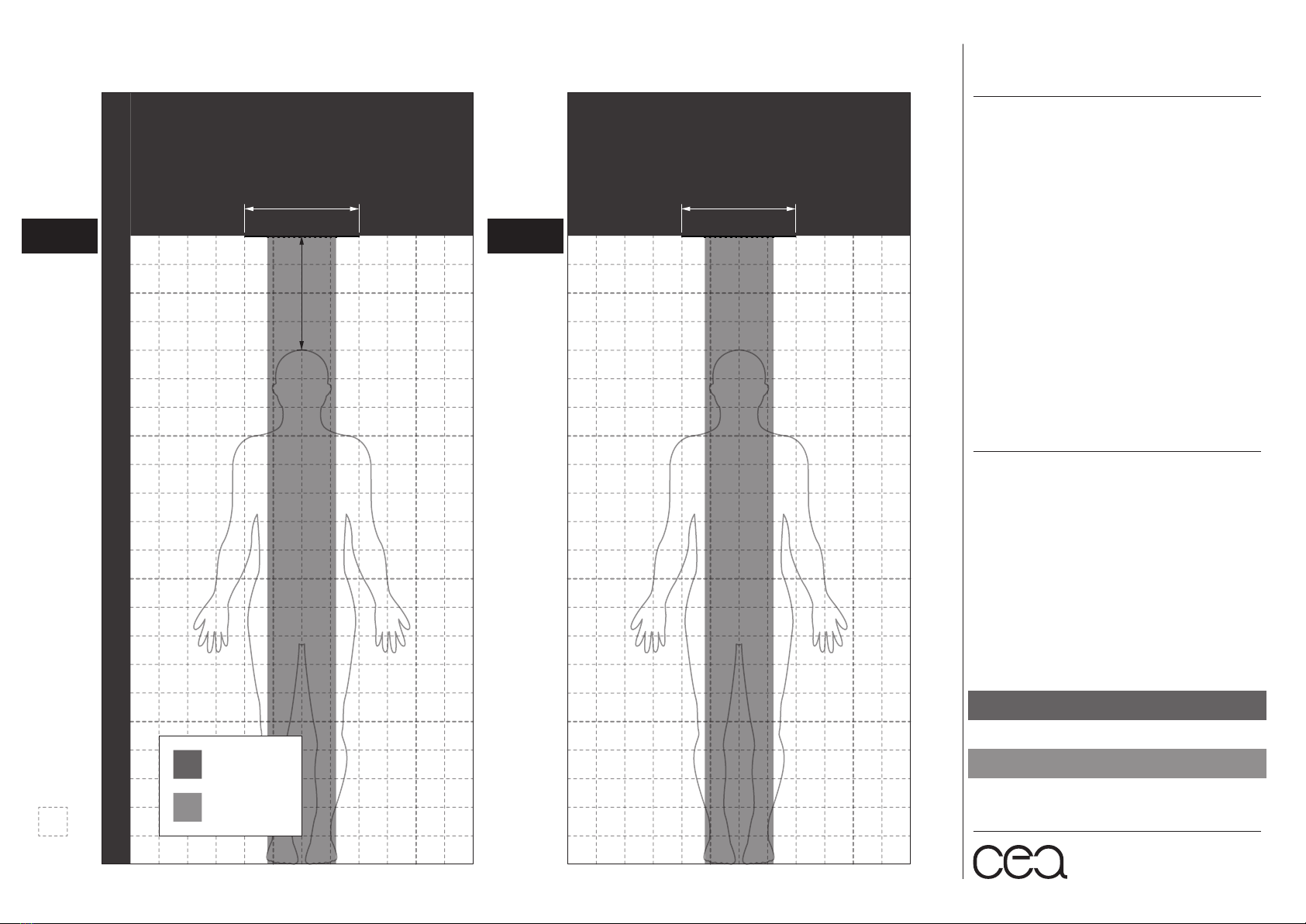
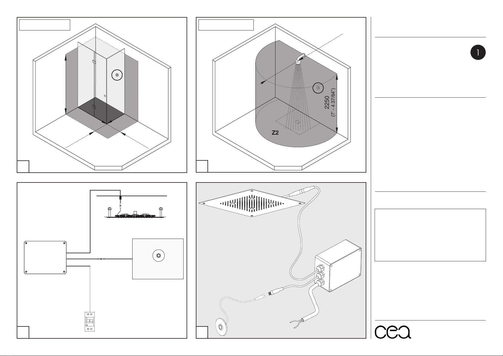
2250
(7’ - 4 37/64”)
600
(1’ - 11 5/8”)
Z0
Z2
Z3
Z1
600
(1’ - 11 5/8”)
2250
(7’ - 4 37/64”)
Z2
Z3
1200
(3’ - 11 1/4”)
Configurazione con box doccia
Configuration with shower box
Configurazione senza box doccia
Configuration without shower box
CONNECTOR
IP65 - 4 poles
LED CONTROL UNIT
POWER SUPPLY
220 V
RCD ≤ 30 mA
PUSH POWER
BUTTON
(ART. CODE BOT02)
(ART. CODE BOT02)
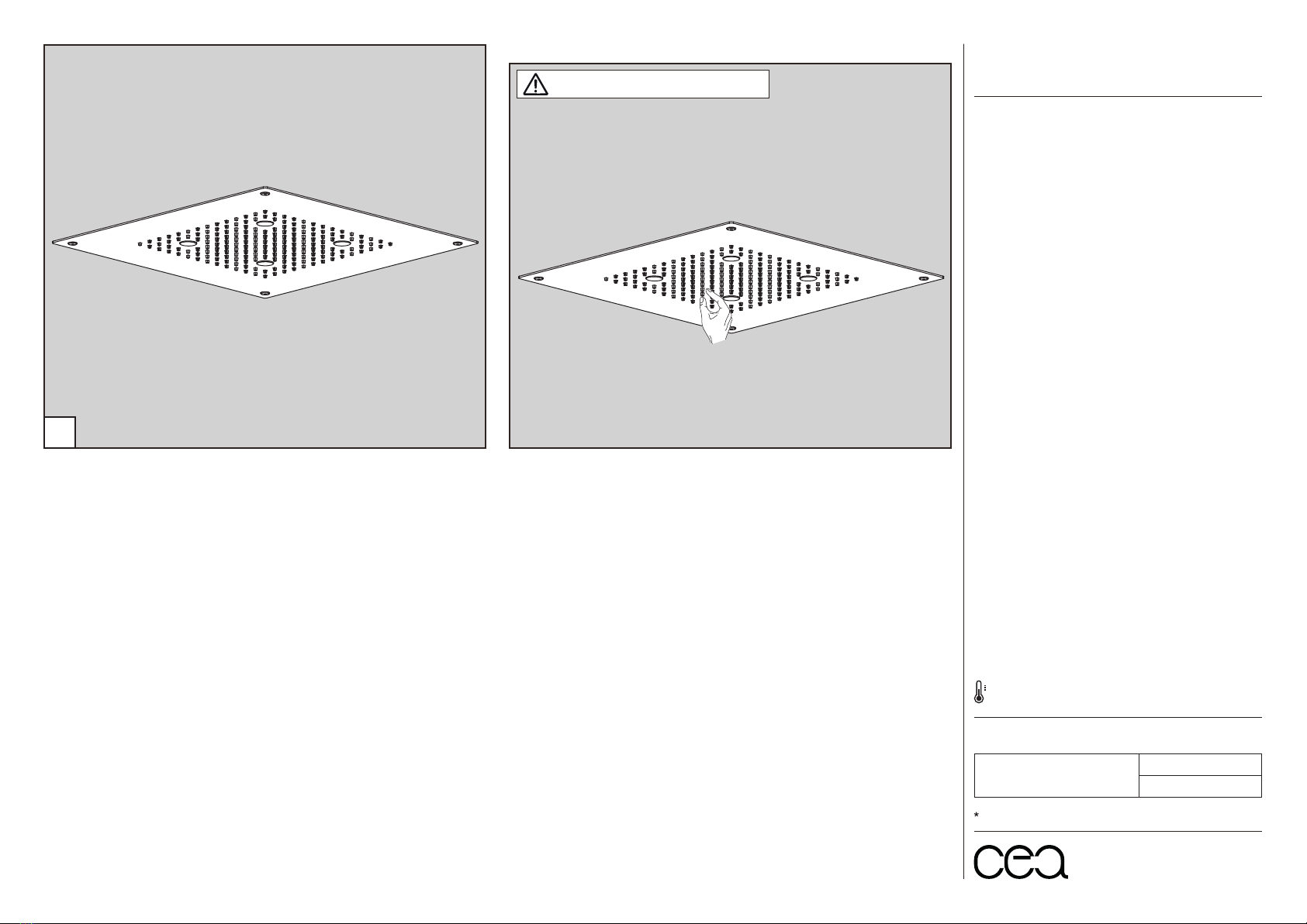
SHOWER HEAD
1
34
2
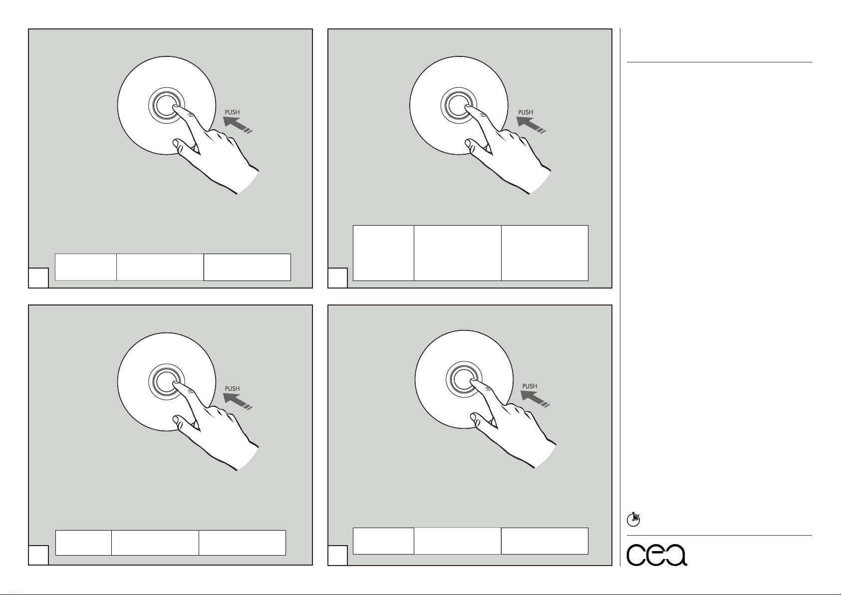
FUNZIONAMENTO LED
/
LED OPERATION
5
CONFIGURAZIONE 1: interruttore On/Off BOT02
/
SETTING 1: push power button BOT02
NORMATIVE IN MATERIA DI SICUREZZA ELETTRICA
ELECTRICAL SAFETY REGULATIONS
Europe EN 60598-1,2
Germany VDE 100, Teil 701
Austria ÖVE-EN 1, Teil 4, § 49
Switzerland NIN 100
France NF.C. 15-100, section 7-701
Luxembourg EVU/VDE 100, Teil 701
Great Britain BS 7671
Netherlands NEN 1010, 727.1+2
Belgium R.G.I.E., Art. 86.10
Italy CEI 64-8/7 sez. 701
1. L’interruttore On/Off BOT02 deve essere posizionato
nella zona Z1, Z2 o Z3, in conformità con le norme UE sulla
sicurezza.
2. La centralina deve essere collegata prima ai LED del soffione
e solo successivamente alla rete elettrica.
3. L’impianto deve essere eseguito da tecnici qualificati e
conformemente alle norme vigenti.
1. The push power button BOT02 must be placed inside zone
Z1, Z2 or Z3, in compliance with the EU safety regulations.
2. The electronic control unit must be connected first to the head
shower LED lights and then to the electric system.
3. The electric system needs to be carried out by skilled technicians
and has to be compliant to the national and international standards.
AVVERTENZE TECNICHE
TECHNICAL WARNINGS