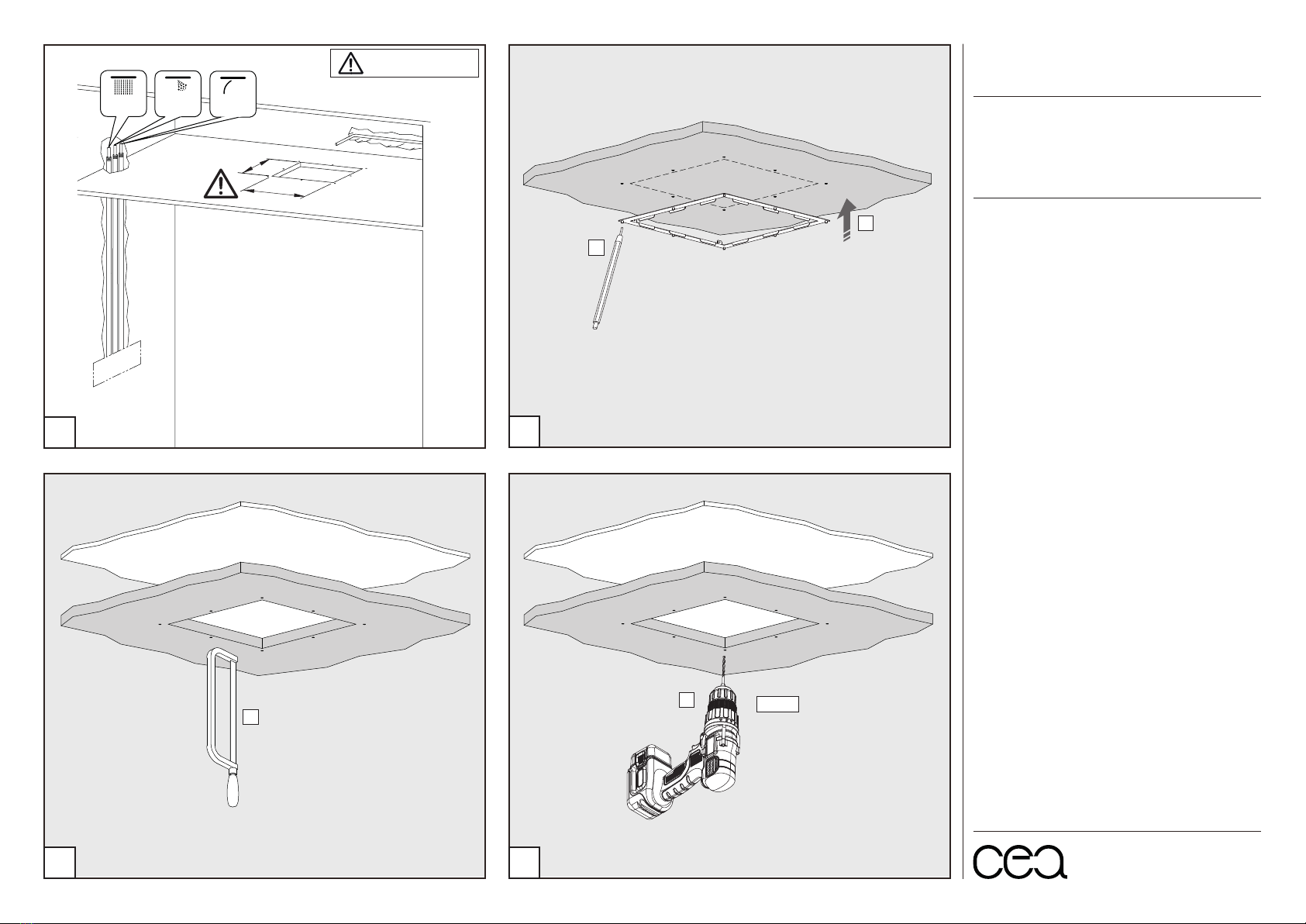
MANUTENZIONE / MAINTENANCE
acido clorico e muriatico
cloric and muriatic acid
acido fluoridrico
hydrofluoric acid
sapone a PH neutro
neutral PH soap
NON UTILIZZARE
DO NOT USE
UTILIZZARE
TO USE PH
7
NaClO
HFl
HCl
ipoclorito di sodio
chlorine bleach
ceadesign.it
Questi disegni sono proprietà di CEADESIGN SRL s.u. pertanto non potranno
essere utilizzati e/o comunicati a terzi, anche in forma parziale, senza preventiva
autorizzazione. CEADESIGN SRL s.u. si riserva il diritto di apportare modifiche ai
disegni al fine di migliorare il prodotto.
CEADESIGN SRL s.u. has the property rights on these drawings, therefore they
cannot be used and/or transferred to third party, even in partial form, without any
prior authorization. Furthermore CEADESIGN SRL s.u. reserves the right to apply
any change to these drawings in order to upgrade the product.
AQC27_ REV11
CEA DESIGN STUDIO
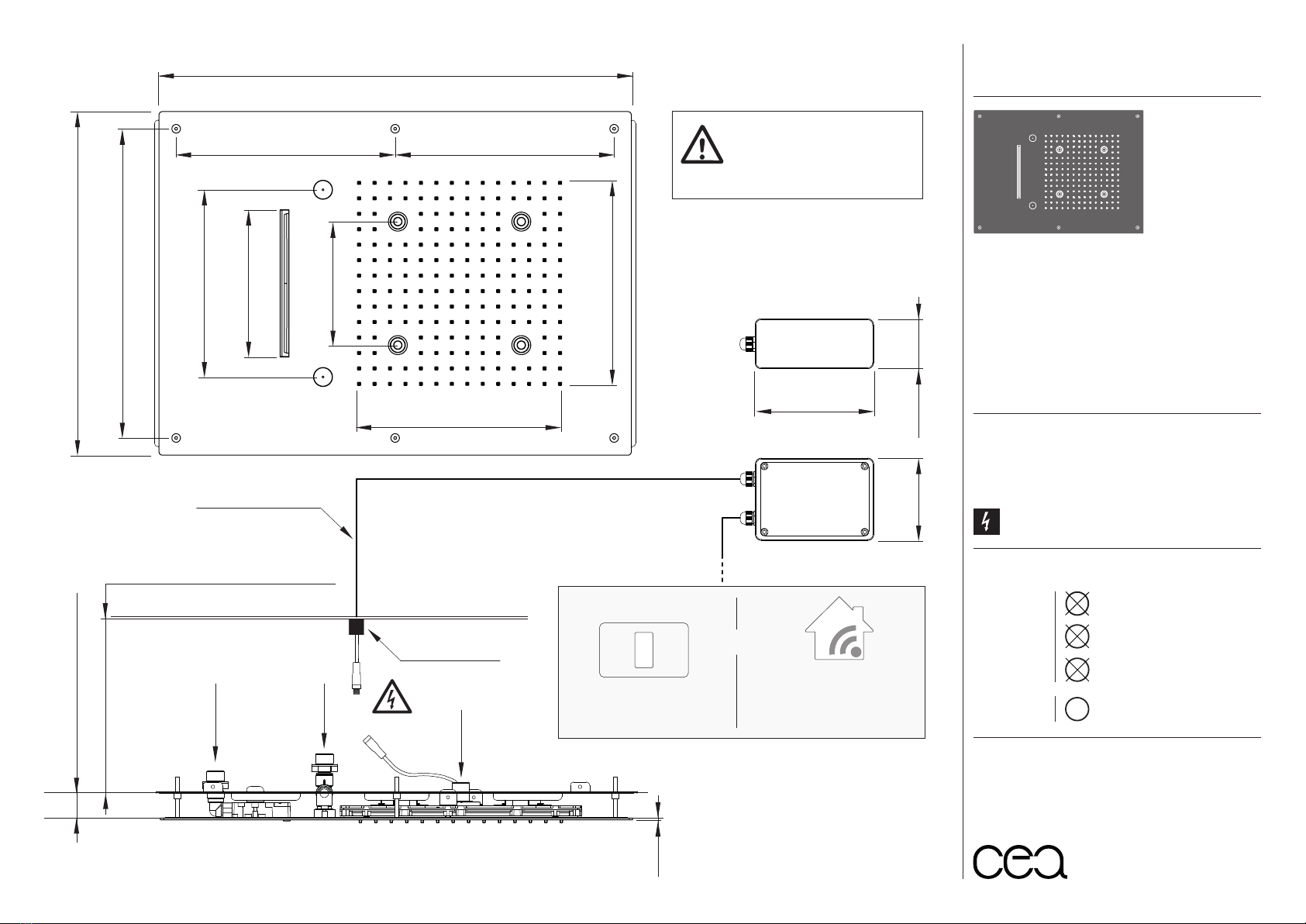
AQC27/FREE IDEAS
AISI 316/L STAINLESS STEEL
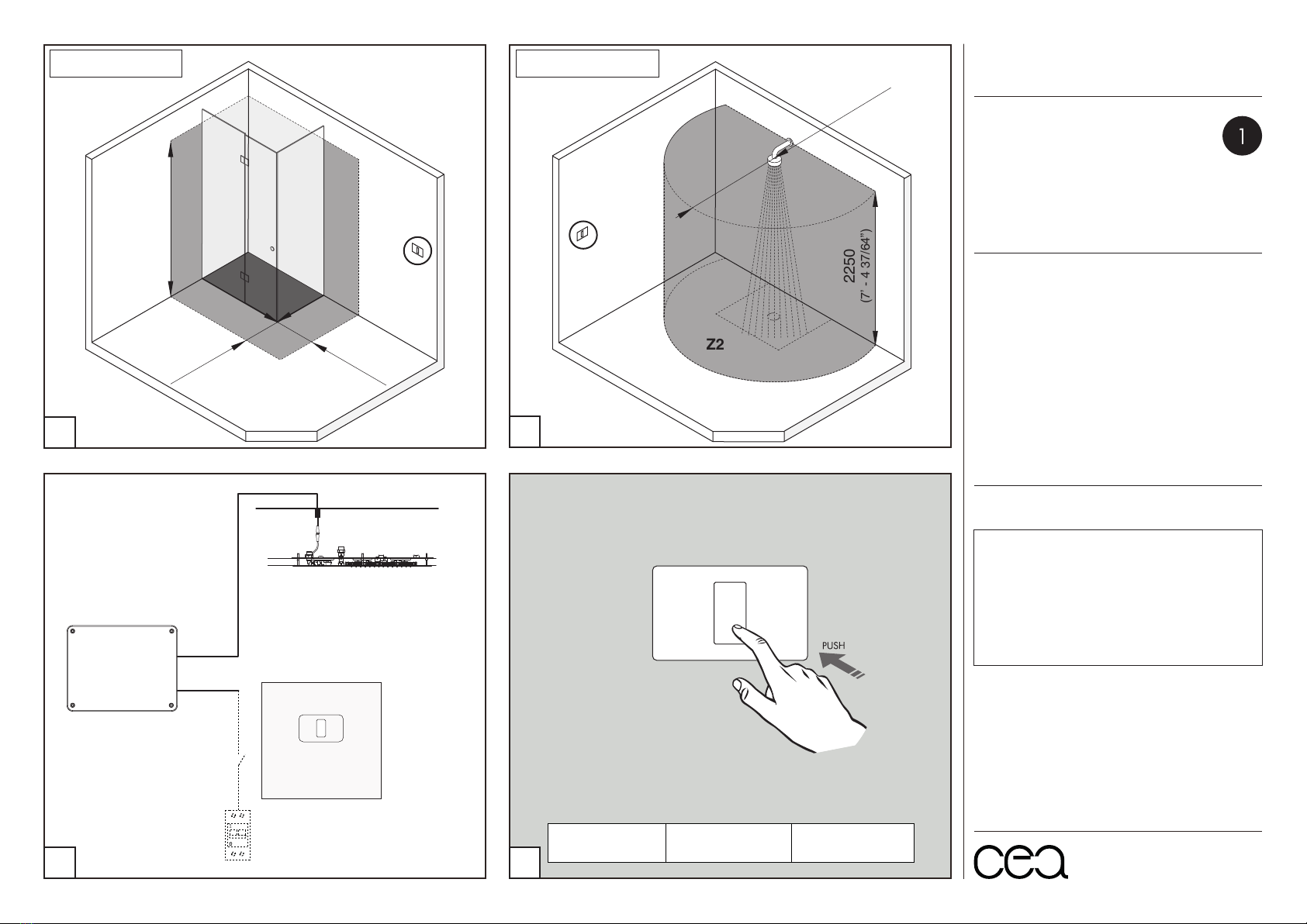
Soffione ad incasso con getto a pioggia, getto nebulizzato, getto a
cascata, LED luce bianca e ugelli in silicone, completo di centralina
di controllo. Da abbinare ad interruttore On/Off non incluso
Built-in shower head with rain, mist, waterfall jets, LED white
light and silicone nozzles. LED control unit included to combine
with an On/Off switch not included
Prodotto che necessita di collegamento elettrico
Product that needs electrical connection
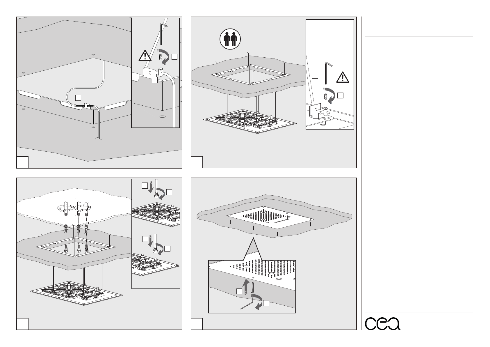
G 1/2”
G 1/2”
G 1/2”
400
(1’ - 3 3/4”)
MIN. 10 mm - MAX. 40 mm
(min. 25/64” - max. 1 37/64”)
MIN. Ø20 mm
(MIN. Ø25/32”)
2
(5/64”)
240
(9 29/64”)
255
(10 3/64”)
255
(10 3/64”)
550
(1’ - 9 21/32”)
240
(9 29/64”)
145
(5 45/64”)
170
(6 11/16”)
220
(8 21/32”)
360
(1’ - 2 11/64”)
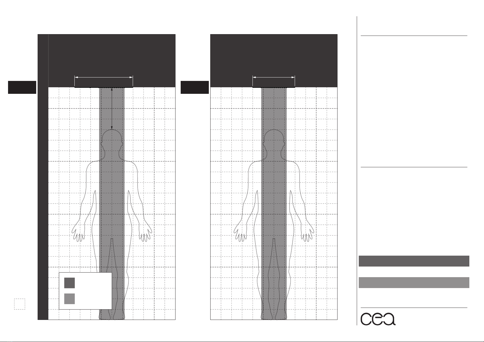
MIN. 160 mm - MAX. 700 mm
(min. 6 19/64” - max. 2’ - 3 9/16”)
130
(5 1/8”)
LED CONTROL UNIT
CENTRALINA
INPUT: 100 - 220VAC 50/60HZ
OUTPUT: 12V
Una centralina di controllo
gestisce un solo soffione /
Each LED control unit operates
only one shower head
90
(3 35/64”)
60
(2 23/64”)
L. 5000 mm (5 m)
(L. 16’ - 4 27/32”)
HOME AUTOMATION
SYSTEMS
SISTEMI DI DOMOTICA
(NOT INCLUDED)
OR
ON/OFF SWITCH
INTERRUTTORE ON/OFF