CEA MATRIX 2200 E Guide

MATRIX 2200 E
IT Manuale d’istruzioni
Lista ricambi
2
67-70
LEGGERE
ATTENTAMENTE
EN Operator’s manual
Spare parts list
7
67-70
READ
CAREFULLY
FR Manuel d’instructions
Liste pièce de rechange
12
67-70
LIRE
ATTENTIVEMENT
DE Bedienungsanleitung
Ersatzteilliste
17
67-70
SORGFÄLTIG
LESEN
ES Manual de instrucciones
Lista repuestos
22
67-70
LEER
ATENTAMENTE
NL Gebruikershandleiding
Onderdelenlijst
27
67-70
EERST GOED
DOORLEZEN
PT Manual de instruções
Lista de peças de substituição
32
67-71
LER
ATENTEMENTE
SV Ågarhandbok
Reservdelslista
37
67-71
LÄS
NOGAS
FI Omistajankäsikirja
Varaosaluettelo
42
67-71
LUE
HUOLELLISESTI
NEierens håndbox
Reservedelliste
47
67-71
LES
NØYE
EL Οδηγιές χρήσεως
Κατάλογος ανταλλακτικών
52
67-71
ΔΙΑΒΑΣΤΕ
ΠΡΟΣΕΚΤΙΚΑ
RU Инструкция по эксплуатации
Список запасных частей
57
67-71
ПЕРЕД НАЧАЛОМ
РАБОТЫ
ВНИМАТЕЛЬНО
ПРОЧТИТЕ
ИНСТРУКЦИЮ
Dis. n° 1020H825/D Cod. n° 200476 Vers. D 03/2013
CEA COSTRUZIONI ELETTROMECCANICHE ANNETTONI S.p.A.
C.so E. Filiberto, 27 - 23900 Lecco - Italy
Tel. ++39.0341.22322 - Fax ++39.0341.422646
Cas. Post. (P.O.BOX) 205

2
ITALIANO
IT
Premessa 2
Descrizione 2
Dati tecnici 3
Limiti d’uso (IEC 60974-1) 3
Metodi di sollevamento dell’impianto 3
Apertura degli imballi 3
Installazione 3
Allacciamento alla linea di utenza 3
Norme d’uso 4
Saldatura elettrodo MMA 4
Saldatura TIG 5
Manutenzione 5
Comandi a distanza e accessori 5
Rilievo di eventuali inconvenienti
e loro eliminazione 6
Sostituzione scheda interfaccia digitale 6
Schema elettrotopografico 62
Legenda schema elettrotopografico 63
Legenda colori 63
Significato dei simboli grafici riportati
sulla macchina 66
Lista ricambi 67-69
Ordinazione dei pezzi di ricambio 70
Descrizione
Potenti, compatti e leggeri, i MATRIX 2200 E grazie all’innovativo
controllo digitale della saldatura sono di quanto più performante e
tecnicamente all’avanguardia si possa trovare fra i generatori per
la saldatura ad elelttrodo.
Grazie al dispositivo PFC Power Factor Correction, che ren-
de sinusoidale la forma d’onda della corrente assorbita con con-
seguente assenza di disturbi armonici in rete ed ottimizzazione
dell’assorbimento di energia dalla rete, i MATRIX 2200 E possono
essere collegati a reti di alimentazione con fusibile da 16 A e que-
sto li rende la soluzione ideale in tutte le applicazioni di saldatura
qualificate ed in lavori di manutenzione dove siano richieste po-
tenza e portabilità. Costruiti con la più recente tecnologia inverter
basata su IGBT, grazie al controllo digitale della saldatura, i MA-
TRIX 2200 E assicurano un’assoluta stabilità dei parametri di sal-
datura e garantiscono saldature di qualità con tutti i tipi di elettrodi,
cellulosici inclusi, ed in TIG con innesco tipo “Lift”.
CARATTERISTICHE
• Design innovativo e compatto.
•
Dimensioni e pesi ridotti per una facile trasportabilità (anche con
cinghia a tracolla).
• Struttura portante in metallo con pannelli in fibra antiurto.
• Visiera di protezione del pannello di controllo.
• Robusta maniglia integrata nel telaio.
•
Frontale inclinato con ampia visibilità da ogni angolazione per
una facile lettura e regolazione dei parametri.
•
Amperometro e voltmetro digitale di serie con pre-impostazione
della corrente di saldatura e memorizzazione dell’ultimo valore.
• Controllo digitale di tutti i parametri di saldatura.
•
Possibilità di memorizzazione dei parametri di saldatura (99 pun-
ti automatici di saldatura - JOB).
• Dispositivo di autodiagnosi.
•
Eccezionali caratteristiche di saldatura con ogni tipo di elettro-
do, cellulosico incluso.
• Saldatura MMA:
- “Arc Force” regolabile digitalmente per la selezione della mi-
gliore caratteristica dinamica dell’arco di saldatura.
-
“Hot Start” regolabile digitalmente per migliorare l’innesco con
elettrodi particolarmente difficili.
- Funzione Antisticking per evitare l’incollaggio degli elettrodi.
• Saldatura TIG:
-
Saldatura TIG con innesco tipo “Lift” a controllo termico (TCS)
che riduce al minimo le inclusioni di tungsteno e permette l’in-
nesco anche sullo spigolo.
-
Esclusivo dispositivo SWS “Smart Welding Stop” per la fine
della saldatura in TIG. Sollevando la torcia senza spegne-
re l’arco si introduce uno slope down con spegnimento au-
tomatico.
• Protezione termostatica contro le sovratemperature.
• Compensazione automatica della tensione di rete ±20%.
• Protezione elettronica contro le variazioni della tensione di rete
e contro le sovracorrenti.
•
Possibilità di attivare il dispositivo vrd (Voltage Reduction Device
- Dispositivo per la riduzione della tensione) che consente l’utiliz-
zo della macchina in ambienti dove il rischio di scossa elettrica
o folgorazione causate dalla saldatura ad arco è enormemen-
te accresciuta per la presenza di acqua, umidità o calore, par-
ticolarmente ove la temperatura ambiente è superiore ai 32°C.
•
Funzione “Energy Saving” che attiva la ventilazione del genera-
tore solo quando necessario.
• Il grado di protezione IP 23 S e le parti elettroniche protette dal-
la polvere, grazie all’innovativo sistema di ventilazione a Tun-
nel ne consentono l’impiego nei più gravosi ambienti di lavoro.
•
Collegabile con elevata affidabilità ai motogeneratori di potenza
adeguata (9 kVA) grazie anche al circuito PFC che garantisce
una maggiore protezione della saldatrice contro le fluttuazioni
della tensione di alimentazione.
• Utilizzabile con cavi di alimentazione oltre 100 m.
• Ridotto consumo di corrente assorbita.
•
Il generatore è inoltre conforme a tutte le normative e direttive
in vigore nella Comunità Europea.
Premessa
Vi ringraziamo per l’acquisto di un nostro prodotto. Per ottenere
dall’impianto le migliori prestazioni ed assicurare alle sue parti la
massima durata, è necessario leggere ed attenersi scrupolosa-
mente alle istruzioni per l’uso contenute in questo manuale e alle
norme di sicurezza contenute nel fascicolo allegato. Se l’im-
pianto necessitasse di manutenzione o di un intervento di ripara-
zione questo manuale vi aiuterà a trovare la soluzione più adatta
a risolvere tutti i vostri problemi, tuttavia si consiglia alla clientela
di far eseguire la manutenzione ed eventualmente la riparazione
dell’impianto, presso le officine della nostra organizzazione di as-
sistenza, in quanto provviste di appropriate attrezzature e di perso-
nale particolarmente qualificato e costantemente addestrato. Tutte
le nostre macchine ed apparecchiature sono soggette ad un con-
tinuo sviluppo. Dobbiamo quindi riservarci modifiche riguardanti
la costruzione e la dotazione.

3
Dati tecnici
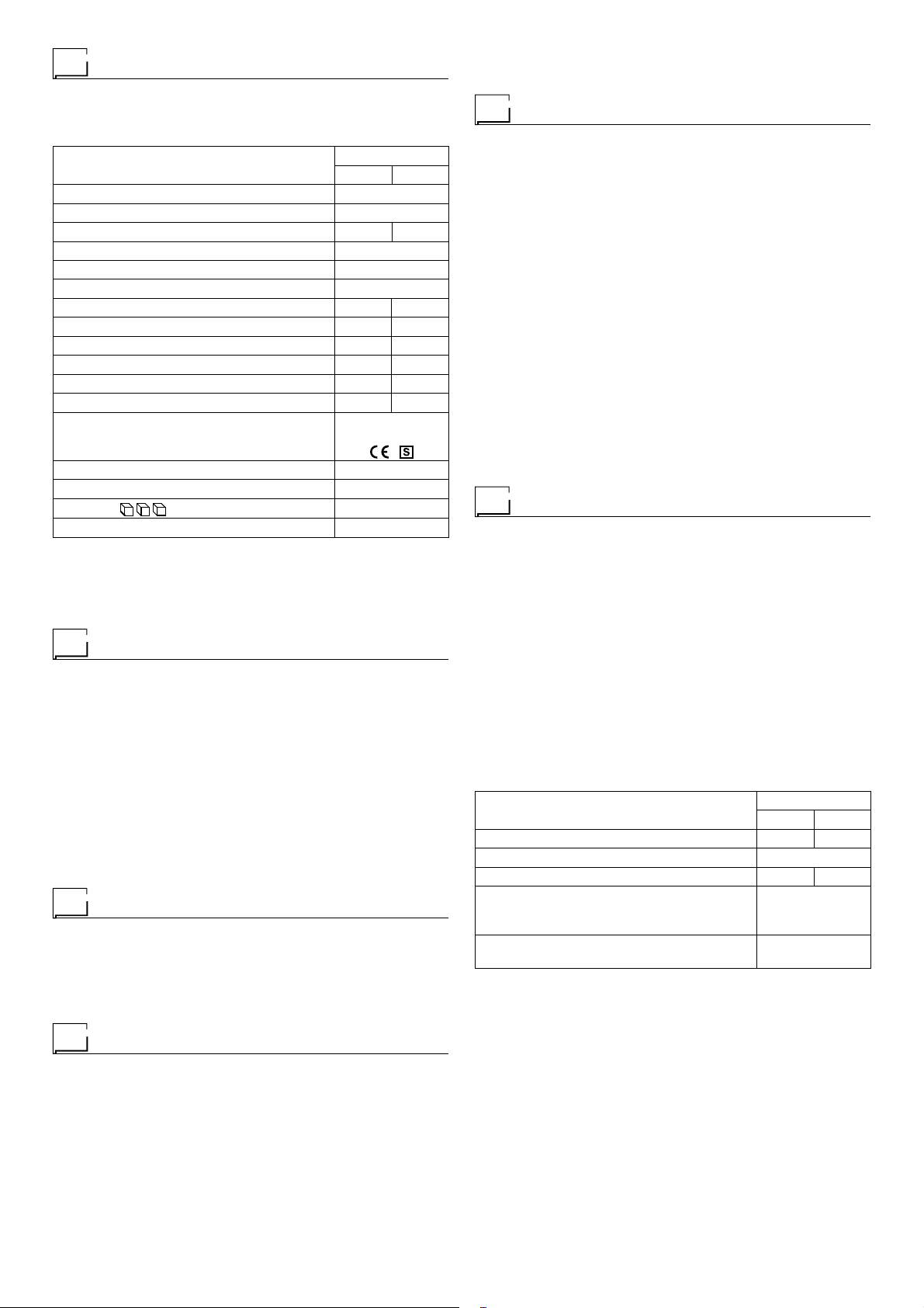
I dati tecnici generali dell’impianto sono riassunti in tabella 1.
Tabella 1
Modello MATRIX 2200 E
MMA TIG
Alimentazione monofase 50/60 Hz V 230 ± 20%
Rete di alimentazione: Zmax (*)
Potenza assorbita @ I2Max kVA 6,2 5,8
Fusibile ritardato (I2@ 100%) A16
Fattore di potenza / cos0,99 / 0,99
Rendimento 0,80
Tensione secondaria a vuoto V 100 10
Campo di regolazione A 5 ÷ 180 5 ÷ 220
Corrente utilizzabile @ 100% (40°C) A 120 140
Corrente utilizzabile @ 60% (40°C) A 150 180
Corrente utilizzabile @ 30% (40°C) A 180 220
Elettrodi utilizzabili mm 1,6÷4,0 1,0÷3,2
Norme di riferimento
IEC 60974-1
IEC 60974-10
Grado di protezione IP 23 S
Classe di isolamento F
Dimensioni mm 430 - 390 - 185
Peso kg 12
(*) IMPORTANTE:
•
Questo impianto soddisfa i requisiti prescritti dalla norma EN/IEC
61000-3-12 in merito alle emissioni armoniche.
•
Questo impianto, collaudato secondo quanto prescritto dalla nor-
ma EN/IEC 61000-3-3, soddisfa i requisiti prescritti dalla norma EN/
IEC 61000-3-11.
Limiti d’uso (IEC 60974-1)
L’utilizzo di una saldatrice è tipicamente discontinuo in quanto com-
posto da periodi di lavoro effettivo (saldatura) e periodi di riposo
(posizionamento pezzi, sostituzione filo, operazioni di molatura,
ecc.). Questa saldatrice è dimensionata per erogare la corrente
I
2
max nominale, in tutta sicurezza, per un periodo di lavoro del
30% rispetto al tempo di impiego totale. Le norme in vigore stabi-
liscono in 10 minuti il tempo di impiego totale. Come ciclo di lavo-
ro viene considerato il 30% di tale intervallo. Superando il ciclo di
lavoro consentito si provoca l’intervento di una protezione termi-
ca che preserva i componenti interni della saldatrice da pericolosi
surriscaldamenti. L’intervento della protezione termica è segnala-
to dal lampeggio del display sul pannello di controllo della scritta
“t °C” (per maggiori informazioni vedi paragrafo sul manuale del
pannello di controllo MX). Dopo qualche minuto la protezione ter-
mica si riarma in modo automatico e la saldatrice è nuovamente
pronta all’uso.
Metodi di sollevamento dell’impianto
La saldatrice è dotata di una robusta maniglia, integrata nel telaio,
che serve esclusivamente per il trasporto manuale della macchina.
NOTA: Questi dispositivi di sollevamento e trasporto sono confor-
mi alle disposizioni prescritte nella norme europee. Non usare altri
dispositivi come mezzi di sollevamento e trasporto.
Apertura degli imballi
L’impianto è costituito essenzialmente da:
• Unità per la saldatura MATRIX 2200 E.
• Cavi di saldatura o RTA torcia TIG (optional).
• Cinghia a tracolla CB 2 (optional).
Eseguire le seguenti operazioni al ricevimento dell’impianto:
•
Togliere il generatore di saldatura e tutti i relativi accessori-com-
ponenti dai relativi imballi.
•
Controllare che l’impianto di saldatura sia in buono stato o al-
trimenti segnalarlo immediatamente al rivenditore distributore.
•
Controllare che tutte le griglie di ventilazione siano aperte e
che non vi siano oggetti che ostruiscano il corretto passaggio
dell’aria.
Installazione
Il luogo di installazione dell’impianto deve essere scelto con cura,
in modo da assicurare un servizio soddisfacente e sicuro.
L’utilizzatore è responsabile dell’installazione e dell’uso dell’im-
pianto in accordo con le istruzioni del costruttore riportate in que-
sto manuale.
Prima di installare l’impianto l’utilizzatore deve tenere in conside-
razione i potenziali problemi elettromagnetici dell’area di lavoro.
In particolare, suggeriamo di evitare che l’impianto sia installato
nella adiacenza di:
• Cavi di segnalazione, di controllo e telefonici.
• Trasmettitori e ricevitori radiotelevisivi.
• Computers o strumenti di controllo e misura.
• Strumenti di sicurezza e protezione.
I portatori di pace-maker, di protesi auricolari e di apparecchiatu-
re similari devono consultare il proprio medico prima di avvicinar-
si all’impianto in funzione. L’ambiente di installazione dell’impianto
deve essere conforme al grado di protezione della carcassa. Que-
sto impianto è raffreddato mediante circolazione forzata di aria e
deve quindi essere disposto in modo che l’aria possa essere fa-
cilmente aspirata ed espulsa dalle aperture praticate nel telaio.
L’unità di saldatura è caratterizzata dalle seguenti classi:
• Classe di protezione IP 23 S indica che il generatore può esse-
re usato sia in ambienti interni che all’aperto.
•
Classe di utilizzo “S” significa che il generatore può essere usato
in ambienti con rischio accresciuto di scosse elettriche.
Allacciamento alla linea di utenza
L’allacciamento della macchina alla linea di utenza è un’ope-
razione che deve essere eseguita solo ed esclusivamente da
personale qualificato.
Prima di collegare la saldatrice alla linea di utenza, controllare
che i dati di targa della stessa corrispondano al valore della
tensione e frequenza di rete e che l’interruttore di linea della
saldatrice sia sulla posizione “O”.
L’allacciamento alla rete di alimentazione deve essere esegui-
to mediante l’utilizzo della spina in dotazione alla saldatrice. Nel
caso si renda necessaria la sostituzione della spina procedere nel
seguente modo:
•
2 conduttori servono per il collegamento della macchina alla rete.
•
Il terzo, di colore GIALLO-VERDE, serve per eseguire il colle-
gamento di “TERRA”.
Il MATRIX 2200 E funziona con interruttori di potenza automati-
ci o fusibili.
La tabella 2 riporta i valori di portata consigliati per fusibili di li-
nea ritardati.
Tabella 2
Modello MATRIX 2200 E
MMA TIG
Potenza assorbita @ I2Max kVA 6,2 5,8
Fusibile ritardato (I2@ 100%) A16
Corrente utilizzabile @ 30% (40°C) A 180 220
Cavo allacciamento rete
Lunghezza
Sezione
m
mm23,5
2,5
Cavo di massa
Sezione mm225
NOTA: Eventuali prolunghe del cavo di alimentazione devono es-
sere di sezione adeguata, in nessun caso inferiore a quella del
cavo di dotazione.

4
Norme d’uso
APPARECCHI DI COMANDO E CONTROLLO (Fig. A)
Pos. 1 Pannello di comando e controllo MX 22. Per informazio-
ni dettagliate sul pannello di controllo, consultare il ma-
nuale istruzioni allegato.
Pos. 2 Connettore 6 poli per comando a distanza.
Pos. 3 Attacco rapido polarità positiva.
Pos. 4 Attacco rapido polarità negativa.
Pos. 5 Interruttore di linea. Nella posizione “O” la saldatrice è
spenta.
Pos. 6 Cavo alimentazione.
Saldatura elettrodo MMA
La saldatura elettrodo si utilizza per saldare la maggior parte dei
metalli (diversi tipi di acciai ecc.) usando degli elettrodi rutilici, ba-
sici e cellulosici che hanno diametri da Ø 1,6 mm a Ø 4,0 mm.
1) Collegamento cavi di saldatura (Fig. B):
Allacciare, sempre a macchina disinserita dalla rete, i cavi di
saldatura ai morsetti d’uscita (Positivo e Negativo) della salda-
trice, collegandoli alla pinza e alla massa con la polarità pre-
vista per il tipo di elettrodo da impiegarsi (Fig. B). Attenersi,
comunque, alle indicazioni fornite dai fabbricanti di elettrodi.
Non toccare contemporaneamente la pinza portaelettrodo e
il morsetto di massa.
2) Mettere in funzione la saldatrice selezionando la posizione 1
sull’interruttore di linea (Pos. 5, Fig. A).
3) Effettuare le regolazioni, selezionare i parametri sul pannello
di controllo MX 22 (leggere attentamente il manuale allegato).
4) Effettuare la saldatura avvicinando la torcia al pezzo da salda-
re. Innescando l’arco (premere velocemente l’elettrodo contro
il metallo e quindi sollevarlo) si provoca la fusione dell’elettro-
do, il cui rivestimento forma una scoria protettiva. In seguito,
continuare la saldatura muovendo l’elettrodo da sinistra ver-
so destra, tenendo un’inclinazione di circa 60° rispetto al me-
tallo in relazione alla direzione di saldatura.
PEZZO DI SALDATURA
Il pezzo da saldare dovrebbe essere sempre collegato a terra per
ridurre le emissioni elettromagnetiche. Occorre però prestare mol-
ta attenzione che il collegamento di terra del pezzo da saldare non
aumenti il rischio di infortuni all’utilizzatore o di danni ad altre ap-
parecchiature elettriche. Quando è necessario collegare il pezzo
da saldare a terra, è opportuno eseguire un collegamento diretto
fra il pezzo ed il pozzetto di terra. Nei Paesi in cui questa connes-
sione non è permessa, collegare il pezzo da saldare alla terra me-
diante opportuni condensatori in accordo con le norme Nazionali.
PARAMETRI DI SALDATURA
La tabella 3 riporta alcune indicazioni generali per la scelta dell’e-
lettrodo in funzione degli spessori da saldare. Nella tabella 4 sono
indicati i valori di corrente da utilizzare con i rispettivi elettrodi per
la saldatura degli acciai comuni e basso legati. Tali dati non han-
no un valore assoluto ma semplicemente orientativo; per una scel-
ta precisa seguire le indicazioni date dai fabbricanti di elettrodi.
La corrente da impiegare dipende dalle posizioni di saldatura, dal
tipo di giunto e varia in modo crescente in funzione dello spesso-
re e delle dimensioni del pezzo.
Il valore dell’intensità di corrente da utilizzare per i vari tipi di sal-
datura, entro il campo di regolazione indicato sulla tabella 4 è:
•
Elevato per le saldature in piano, in piano frontale e verticale
ascendente.
• Medio per le saldature sopratesta.
•
Basso per la saldatura verticale discendente e per unire pezzi
di piccole dimensioni preriscaldati.
1
2
4
5
6
3
FIG. A
Tabella 3
SPESSORE DI SALDATURA
(mm) Ø ELETTRODO (mm)
1,5 ÷ 3
3 ÷ 5
5 ÷ 12
12
2
2,5
3,2
4
Tabella 4
Ø ELETTRODO (mm) CORRENTE (A)
1,6
2
2,5
3,2
4
30 ÷ 60
40 ÷ 75
60 ÷ 110
95 ÷ 140
140 ÷ 190

5
-
Collegare la relativa pinza massa al pezzo da saldare
o al piano portapezzi in zona libera da ruggine, vernice,
grasso, ecc.
-
Collegare il cavo di potenza della torcia TIG alla con-
nessione rapida contrassegnata dal simbolo - (negativo).
2) Mettere in funzione la saldatrice selezionando la posizione 1
sull’interruttore di linea (Pos. 5, Fig. A).
3) Effettuare le regolazioni, selezionare i parametri sul pannello
di controllo MX 22 (leggere attentamente il manuale allegato).
4) Aprire la bombola del gas e regolare il flusso ruotando ma-
nualmente la valvola posta sulla torcia TIG.
5) Innescare, per contatto, alla corrente di saldatura impostata,
l’arco voltaico con un movimento deciso e rapido (innesco tipo
“Lift” - Fig. D).
Per ultimare la saldatura:
• Sollevare lentamente la torcia, ad un certo punto la corren-
te di saldatura decresce, quindi fermarsi.
• La saldatrice esegue uno slope down automatico con rela-
tivo spegnimento dell’arco.
6) A saldatura ultimata ricordarsi di chiudere la valvola della tor-
cia e della bombola del gas.
Manutenzione
ATTENZIONE: Prima di effettuare qualsiasi ispezione all’interno
del generatore togliere l’alimentazione all’impianto.
RICAMBI
I ricambi originali sono stati specificatamente progettati per il no-
stro impianto. L’impiego di ricambi non originali può causare va-
riazioni nelle prestazioni e ridurre il livello di sicurezza previsto.
Per danni conseguenti dall’uso di ricambi non originali decliniamo
ogni responsabilità.
GENERATORE
Essendo questi impianti completamente statici, procedere nel se-
guente modo:
• Rimozione periodica degli accumuli di sporco e polvere dall’in-
terno del generatore per mezzo di aria compressa. Non dirigere
il getto d’aria direttamente sui componenti elettrici che potreb-
bero danneggiarsi.
•
Ispezione periodica al fine di individuare cavi logori o connessio-
ni allentate che sono la causa di surriscaldamenti.
Comandi a distanza e accessori
I generatori MATRIX 2200 E possono essere equipaggiati con di-
versi comandi a distanza ed accessori, quali:
• Comando a distanza manuale CD 6.
Con questo accessorio inserito si può regolare a distanza solo la
corrente di saldatura, il cui valore verrà visualizzato sul display
della saldatrice.
Il controllo digitale del generatore è dotato di un dispositivo di au-
toriconoscimento del comando utilizzato che gli consente di ca-
pire quale dispositivo è collegato e comportarsi di conseguenza.
Il comando a distanza può essere connesso, indifferentemente,
sia a saldatrice spenta che accesa.
NOTA: Il pannello di controllo MX è dotato della funzione STAND-
BY che, quando è inserito il comando a distanza, spegne l’inver-
ter al raggiungimento del valore minimo della corrente di saldatura
(per ripristinare il normale e corretto funzionamento della macchi-
FIG. B
FIG. C
2000HA912000HA94
Un’indicazione, abbastanza approssimata, della corrente media
da impiegare nella saldatura di elettrodi per acciaio normale è for-
nita dalla seguente formula:
I = 50 × (Øe - 1)
Dove:
I = intensità di corrente di saldatura
Øe = diametro dell’elettrodo
Esempio:
Diametro elettrodo 4 mm
I = 50 × (4 - 1) = 50 × 3 = 150A
Saldatura TIG
La saldatura TIG fonde il metallo del pezzo da saldare, utilizzan-
do un arco innescato da un elettrodo di tungsteno. Il bagno di fu-
sione e l’elettrodo sono protetti dal gas (Argon). Si rivela utile per
saldare lamiere sottili e quando è richiesta una elevata qualità.
1) Collegamento cavi di saldatura (Fig. C):
• Allacciare il tubo gas da un’estremità all’attacco gas posto
sul dinse della torcia TIG e dall’altra estremità alla bombo-
la di gas Argon.
• A macchina spenta:
- Collegare il cavo di massa alla connessione rapida con-
trassegnata dal simbolo + (positivo).
FIG. D
2000HA86

6
na aumentare il valore della corrente di saldatura ruotando la ma-
nopola del comando a distanza).
Rilievo di eventuali inconvenienti
e loro eliminazione
Alla linea di alimentazione va imputata la causa dei più frequenti
inconvenienti. In caso di guasto procedere come segue:
1) Controllare il valore della tensione di linea.
2) Controllare il perfetto allacciamento del cavo di alimentazione
alla spina e all’interruttore di rete.
3) Verificare che i fusibili di rete non siano bruciati o allentati.
4) Controllare se sono difettosi:
• L’interruttore che alimenta la macchina.
• La presa a muro della spina.
• L’interruttore del generatore.
NOTA: Date le necessarie conoscenze tecniche che richiede la
riparazione del generatore, si consiglia, in caso di rottura, di rivol-
gersi a personale qualificato oppure alla nostra assistenza tecnica.
Sostituzione scheda interfaccia digitale
• Svitare le 4 viti che fissano il pannello rack frontale.
• Rimuovere la manopola di regolazione.
• Estrarre i connettori elettrici della scheda.
• Svitare le colonnine di supporto.
• Rimuovere la scheda sollevandola dai propri supporti.
• Per montare la nuova scheda procedere in senso inverso.

7
ENGLISH
EN
Introduction 7
Description 7
Technical data 8
Usage limits (IEC 60974-1) 8
How to lift up the machine 8
Open the packaging 8
Installation 8
Connection to the electrical supply 8
Instructions for use 9
MMA electrode welding 9
TIG welding 10
Maintenance 10
Remote controls and accessories 10
The pointing out of any difficulties and their
elimination 11
Digital interface PCB replacement 11
Electro topographical diagram 62
Electro topographical diagram key 63
Colour key 63
Meaning of graphic symbols on machine 66
Spare parts list 67-69
Ordering spare parts 70
Description
Powerful, compact, and light-weight - thanks to the innovative
digital welding control the MATRIX 2200 E units are the highest
performance and most technically advanced electrode welding
generators you can find.
Thanks to the PFC (Power Factor Correction) device that gives
the wave for the absorbed current a sinusoidal shape, and so does
away with harmonic disturbance in the network and optimises the
absorption of energy from the mains, the MATRIX 2200 E can
be connected to the mains power supply with a 16 A fuse, which
makes them the ideal solution for all approved welding applica-
tions, as well as maintenance work that requires power and port-
ability. Made using the latest inverter technology based on IGBT,
thanks to the digital welding control the MATRIX 2200 E machines
ensure absolute stability of welding parameters and guarantee
quality welds with all types of electrodes, including cellulose, as
well as TIG with “Lift” ignition.
FEATURES
• Innovative and compact design.
•
Compact size and light weight for easy transportation (also with
strap).
• Metallic main structure with shock-proof plastic front panel.
• Protective visor on the control panel.
• Robust handle integrated into the chassis.
• Slanting front panel with wide range of visibility from all angles
to facilitate reading and adjusting parameters.
• Digital ammeters and voltmeters are standard fittings, with pre-
setting of welding current and saving of the latest value.
• Digital control of all welding parameters.
•
Possibility of saving the welding parameters (99 automatic weld-
ing points - JOBS).
• Self-diagnosis device.
•
Exceptional welding characteristics for all types of electrode, in-
cluding cellulosic.
• MMA welding:
-
“Arc Force” adjustable to select the best dynamic character-
istics for the welding arc.
- “Hot Start” adjustable to improve ignition with particularly dif-
ficult electrodes.
- Anti-sticking function to avoid the electrodes sticking.
• TIG welding:
-
TIG welding with thermal controlled (TCS) “Lift” type striking
reducing tungsten inclusions to a minimum and allowing to
also strike on sharp edges.
-
Exclusive SWS “Smart Welding Stop” system to finish TIG
welding. Lifting up the torch without turning off the arc will
achieve a slope down and it automatically switches off.
• Overheating thermostatic protection.
•
Automatic compensation for mains voltage fluctuations within
±20%.
• Safety barrier against excess voltage from mains.
• Possibility of activating a VRD (Voltage Reduction Device) that
makes it possible to use the machine in environments in which
the risk of electric shock or electrocution caused by arc weld-
ing is much higher due to the presence of water, damp, or heat,
particularly where the ambient temperature is higher than 32°C.
• “Energy Saving” function that starts ventilation of the generator
only when necessary.
• IP 23 S protection class and dust-proof electronic components,
thanks to the innovative “Tunnel” fan cooling system, allow op-
eration in the toughest work environments.
•
Connectable with a high degree of reliability to motor powered
generators of adequate power (9 kVA), thanks also to the PFC
circuit that guarantees greater protection of the welding machine
against fluctuations in the power supply voltage.
• Useable with power supply cables more than 100 m long.
• Low absorbed current consumption.
•
This generator also conforms to all the standards and directives
in force in the European Community.
Introduction
Thank you for purchasing one of our products. Please read instruc-
tions on use in this manual as well as the safety rules given in
the attached booklet and follow them carefully to get the best
performance from the equipment and be sure that the parts have
the longest service life possible. In the interest of customers, you
are recommended to have maintenance and, where necessary,
repairs carried out by the workshops of our service organisation,
since they have suitable equipment and specially trained person-
nel available. All our machinery and systems are subject to con-
tinual development. We must therefore reserve the right to modify
their construction and properties.

8
Technical data
The general technical data of the system are summarized in ta-
ble 1.
Table 1
Model MATRIX 2200 E
MMA TIG
Single-phase input 50/60 Hz V 230 ± 20%
Power supply: Zmax (*)
Input power @ I2Max kVA 6,2 5,8
Delayed fuse (I2@ 100%) A16
Power factor / cos0,99 / 0,99
Efficiency degree 0,80
Open circuit voltage V 100 10
Current range A 5 ÷ 180 5 ÷ 220
Duty cycle @ 100% (40°C) A 120 140
Duty cycle @ 60% (40°C) A 150 180
Duty cycle @ 30% (40°C) A 180 220
Usable electrodes mm 1,6÷4,0 1,0÷3,2
Standards
IEC 60974-1
IEC 60974-10
Protection class IP 23 S
Insulation class F
Dimensions mm 430 - 390 - 185
Weight kg 12
(*) IMPORTANT:
•
This equipment meets the requirements laid down in the EN/IEC
61000-3-12 standard on harmonic currents.
•
This system, tested according to EN/IEC 61000-3-3, meets the re-
quirements of EN/IEC 61000-3-11.
Usage limits (IEC 60974-1)
The use of a welder is typically discontinuous, in that it is made up
of effective work periods (welding) and rest periods (for the posi-
tioning of parts, the replacement of wire and underflushing opera-
tions etc. This welder is dimensioned to supply a I2max nominal
current in complete safety for a period of work of 30% of the to-
tal usage time. The regulations in force establish the total usage
time to be 10 minutes. The work cycle is considered to be 30% of
this period of time. If the permitted work cycle time is exceeded,
an overheat cut-off occurs to protect the components around the
welder from dangerous overheating. Activation of thermal protec-
tion is signaled by “t° C” flashing on control panel display (for fur-
ther information see the paragraph in the manual for the MX control
panel). After several minutes the overheat cut-off rearms automat-
ically and the welder is ready for use again.
How to lift up the machine
The weld machine has a strong handle all in one with the frame,
used for transporting the machine manually only.
NOTE: These hoisting and transportation devices conform to Eu-
ropean standards. Do not use other hoisting and transportation
systems.
Open the packaging
The system essentially consists of:
• MATRIX 2200 E weld unit.
• Welding cables or RTA TIG torch (optional).
• Neck strap CB 2 (optional).
Upon receiving the system:
•
Remove the welding generator and all relevant accessories-
components from their packaging.
•
Check that the weld machine is in good condition, if not report
any problems immediately to the seller-distributor.
•
Make sure all ventilation grilles are open and that no foreign bod-
ies are blocking the air circulation.
Installation
The installation site for the system must be carefully chosen in or-
der to ensure its satisfactory and safe use. The user is responsi-
ble for the installation and use of the system in accordance with
the producer’s instructions contained in this manual. Before install-
ing the system the user must take into consideration the potential
electromagnetic problems in the work area. In particular, we sug-
gest that you should avoid installing the system close to:
• Signalling, control and telephone cables.
• Radio and television transmitters and receivers.
• Computers and control and measurement instruments.
• Security and protection instruments.
Persons fitted with pace-makers, hearing aids and similar equip-
ment must consult their doctor before going near a machine in op-
eration. The environment in which the equipment is installed must
be suitable for the casing’s protection level. This system is cooled
by means of the forced circulation of air, and must therefore be
placed in such a way that the air may be easily sucked in and ex-
pelled through the apertures made in the frame.
The welding unit is characterised by the following levels:
•
Protection level IP 23 S indicates that the equipment can be used
both indoors and outdoors.
• Use class “S” means that the equipment can be used in condi-
tions subject to heightened electrical shock.
Connection to the electrical supply
Connection of the machine to the user line (electrical current)
must be performed by qualified personnel.
Before connecting the welder to the electrical supply, check
that the machine’s plate rating corresponds to the supply volt-
age and frequency and that the line switch of the welder is in
the “O” position.
Use the welder’s own plug to connect it up to the main power sup-
ply. Proceed as follows if you have to replace the plug:
•
2 conducting wires are needed for connecting the machine to
the supply.
• The third, which is YELLOW GREEN in colour is used for mak-
ing the “GROUND” connection.
MATRIX 2200 E works with circuit breaker or fusible power switch-
es.
Table 2 shows the capacity values that are recommended for fus-
es in the line with delays.
Table 2
Model MATRIX 2200 E
MMA TIG
Input power @ I2Max kVA 6,2 5,8
Delayed fuse (I2@ 100%) A16
Duty cycle @ 30% (40°C) A 180 220
Mains cable
Length
Section
m
mm23,5
2,5
Ground cable
Section mm225
NOTE: Any extensions to the power cable must be of a suitable
diameter, and absolutely not of a smaller diameter than the spe-
cial cable supplied with the machine.

9
Instructions for use
COMMAND AND CONTROL UNITS (Fig. A)
Pos. 1 MX 22 command and control panel. For detailed infor-
mation on the control panel, see the instruction manual
enclosed.
Pos. 2 6 pole remote control connector.
Pos. 3 Positive pole quick connection.
Pos. 4 Negative pole quick connection.
Pos. 5 Supply switch. In the “O” position the welder is off.
Pos. 6 Mains cable.
MMA electrode welding
Electrode welding is used for welding most metals (various types
of steels, etc.) using rutilic, basic, and cellulosic electrodes with
diameters from 1.6 mm to 4.0 mm.
1) Connecting the welding cables (Fig. B):
Disconnect the machine from the mains power supply and con-
nect the welding cables to the output terminals (Positive and
Negative) of the welding machine, attaching them to the clamp
and ground with the polarity specified for the type of electrode
being used (Fig.B). Always follow the electrode manufactur-
er’s instructions. The welding cables must be as short as pos-
sible, they must be near to one another, positioned at or near
floor level. Do not touch the electrode clamp and the ground
clamp simultaneously.
2) Start the welding machine by selecting position 1 on the line
switch (Pos. 5, Fig. A).
3) Make the adjustments and select the parameters on the MX
22 control panel (read the enclosed manual carefully).
4) Carry out welding by moving the torch to the workpiece. Strike
the arc (press the electrode quickly against the metal and then
lift it) to melt the electrode, the coating of which forms a protec-
tive residue. Then continue welding by moving the electrode
from left to right, inclining it by about 60° compared with the
metal in relation to the direction of welding.
PART TO BE WELDED
The part to be welded must always be connected to ground in or-
der to reduce electromagnetic emission. Much attention must be
afforded so that the ground connection of the part to be welded
does not increase the risk of accident to the user or the risk of dam-
age to other electric equipment. When it is necessary to connect
the part to be welded to ground, you should make a direct con-
nection between the part and the ground shaft. In those countries
in which such a connection is not allowed, connect the part to be
welded to ground using suitable capacitors, in compliance with the
national regulations.
WELDING PARAMETERS
Table 3 shows some general indications for the choice of elec-
trode, based on the thickness of the parts to be welded. The val-
ues of current to use are shown in the table with the respective
electrodes for the welding of common steels and low-grade alloys.
These data have no absolute value and are indicative data only.
For a precise choice follow the instructions provided by the elec-
trode manufacturer.
The current to be used depends on the welding positions and the
type of joint, and it increases according to the thickness and di-
mensions of the part.
The current intensity to be used for the different types of welding,
within the field of regulation shown in table 4 is:
• High for plane, frontal plane and vertical upwards welding.
• Medium for overhead welding.
•
Low for vertical downwards welding and for joining small pre-
heated pieces.
1
2
4
5
6
3
FIG. A
Table 3
WELDING THICKNESS (mm) Ø ELECTRODE (mm)
1,5 ÷ 3
3 ÷ 5
5 ÷ 12
12
2
2,5
3,2
4
Table 4
Ø ELECTRODE (mm) CURRENT (A)
1,6
2
2,5
3,2
4
30 ÷ 60
40 ÷ 75
60 ÷ 110
95 ÷ 140
140 ÷ 190

10
A fairly approximate indication of the average current to use in
the welding of electrodes for ordinary steel is given by the follow-
ing formula:
I = 50 × (Øe - 1)
Where:
I = intensity of the welding current
Øe = electrode diameter
Example:
For electrode diameter 4 mm
I = 50 × (4 - 1) = 50 × 3 = 150A
TIG welding
TIG welding melts the metal of the workpiece, using an arc struck
by a tungsten electrode. The fusion bath and the electrode are
protected by gas (Argon). This type of welding is used to weld thin
sheet metal or when elevated quality is required.
1) Connecting the welding cables (Fig. C):
•
Connect one end of the gas hose to the gas connecter on
the TIG torch and the other end to the Argon cylinder and
open it.
• With the machine switched off:
-
Connect the ground cable to the snap-on connector
marked + (positive).
-
Connect the relative ground clamp to the workpiece or
to the workpiece support in an area free of rust, paint,
grease, etc..
FIG. B
FIG. C
-
Connect the TIG torch power cable to the snap-on con-
nector marked - (negative).
2) Start the welding machine by selecting Pos. 1 on the line
switch (Pos. 5, Fig. A).
3) Make the adjustments and select the parameters on the MX
22 control panel (read the enclosed manual carefully).
4) Open the gas cylinder and regulate the flow by adjusting the
valve on the TIG torch by hand.
5) Ignite the electric arc by contact, using a decisive, quick move-
ment at the welding current set (“Lift” type ignition - Fig. D).
To end welding:
•
Lift the torch slowly, at a certain point the welding current
decreases, and then stop.
•
The welding machine follows an automatic down slope
along with extinguishing of the arc.
6) When you have finished welding remember to shut the valve
on the torch and the gas cylinder.
Maintenance
ATTENTION: Before carrying out any inspection of the inside of
the generator, disconnect the system from the supply.
SPARE PARTS
Original spare parts have been specially designed for our equip-
ment. The use of non-original spare parts may cause variations in
performance or reduce the foreseen level of safety.
We decline all responsibility for the use of non-original spare parts.
GENERATOR
As these systems are completely static, proceed as follow:
•
Periodic removal of accumulated dirt and dust from the inside
of the generator, using compressed air. Do not aim the air jet
directly onto the electrical components, in order to avoid dam-
aging them.
• Make periodical inspections in order to individuate worn cables
or loose connections that are the cause of overheating.
Remote controls and accessories
MATRIX 2200 E generators can be fitted with various remote con-
trol devices and accessories, including:
• CD 6 manual remote control.
When this accessory is activated the welding current can only be
remote controlled, and this value will be shown on the welding ma-
chine’s display.
The digital control unit of the generator is fitted with a control rec-
ognition device which allows it to identify which device is connect-
ed and take action accordingly.
The remote control can be connected whether the welding ma-
chine is on or off.
NOTE: The MX control panel has a STAND-BY function that, when
the remote control is on, switches off the inverter when the mini-
mum welding current value is reached (to reinstate normal, correct
functioning of the machine, increase the welding current value by
rotating the remote control knob).
2000HA912000HA94
FIG. D
2000HA86

11
The pointing out of any difficulties
and their elimination
The supply line is attributed with the cause of the most common
difficulties. In the case of breakdown, proceed as follows:
1) Check the value of the supply voltage
2) Check that the power cable is perfectly connected to the plug
and the supply switch
3) Check that the power fuses are not burned out or loose
4) Check whether the following are defective:
• The switch that supplies the machine.
• The plug socket in the wall.
• The generator switch.
NOTE: Given the required technical skills necessary for the repair
of the generator, in case of breakdown we advise you to contact
skilled personnel or our technical service department.
Digital interface PCB replacement
• Unscrew the 4 screws fastening the front rack panel.
• Remove the adjustment knob.
• Extract wiring connectors from the digital interface PCB.
• Unscrew small supporting columns.
• Remove the digital interface PCB by lifting it out of its supports.
• Proceed vice versa to assemble the new digital interface PCB.

12
FRANÇAIS
FR
Avant-propos 12
Description 12
Donnees techniques 13
Limites d’utilisation (IEC 60974-1) 13
Méthodes de levage de l’installation 13
Ouverture des emballages 13
Installation 13
Branchement a la ligne d’utilisation 13
Mode d’emploi 14
Soudage électrode MMA 14
Soudage TIG 15
Maintenance 15
Commandes à distance et accessoires 15
Releve des eventuels inconvenients et leur
elimination 16
Substitution fiche interface numérique 16
Schéma électrophotographique 62
Légende schéma électrophotographique 63
Légende couleurs 63
Interprétation des symboles graphiques reportés
sur la machine 66
Liste pièces de rechange 67-69
Commade des pièces de rechange 70
Description
MATRIX 2200 E: puissants, compacts et légers. Grâce au nou-
veau contrôle numérique du soudage, ces générateurs pour sou-
dage à électrode sont à la de pointe de la technique et les plus
performants du marché.
Grâce au dispositif PFC Power Factor Correction, qui rend la
forme d’onde du courant absorbé sinusoïdale, permettant ainsi
d’éliminer les parasites harmoniques sur le réseau et d’optimiser
l’absorption d’énergie par ce dernier, les MATRIX 2200 E peuvent
être reliés à des réseaux d’alimentation dotés de fusibles de 16
A, ce qui en fait la solution idéale pour toutes les applications
de soudage qualifiées et pour tous les travaux de maintenance
où puissance et portabilité sont requises. Conçus au moyen de
la technologie inverter la plus récente, basée sur IGBT, les MA-
TRIX 2200 E assurent, grâce au contrôle numérique du soudage,
une stabilité absolue des paramètres de soudage, des soudures
de qualité avec tout type d’électrodes, y compris cellulosiques, et
un soudage TIG avec amorçage de type «Lift».
CARACTÉRISTIQUES
• Design compact et innovatif.
•
Dimensions et poids réduits pour faciliter le transport (même
en bandoulière).
•
Structure principale métallique avec panneau frontal anti-choc
en plastique.
• Visière de protection du panneau de contrôle.
• Poignées robustes faisant partie du châssis.
•
Avant incliné avec grande visibilité avec n’importe quel angle,
permettant de lire et régler facilement les paramètres.
•
Ampèremètre et voltmètre numérique de série avec pré-confi-
guration du courant de soudage et mémorisation de la dernière
valeur.
• Contrôle numérique de tous les paramètres de soudage.
•
Possibilité de mémoriser les paramètres de soudage (99 points
automatiques de soudage - JOBS).
• Dispositif d’autodiagnostic.
•
Exceptionnelles caractéristiques de soudage avec tous les types
d’électrode, y compris cellulosique.
• Soudage MMA:
-«Arc Force» réglable pour la sélection de la meilleure carac-
téristique dynamique de l’arc de soudage.
-
«Hot Start» réglable pour améliorer l’amorçage avec des élec-
trodes particulièrement difficiles.
-
Fonction Antisticking pour éviter que les électrodes se collent.
• Soudage TIG:
-
Soudure TIG avec amorçage «Lift» à contrôle thermique
(TCS) pour réduire au maximum les inclusions de tungstène
et avoir un amorçage même sur l’arête.
- Dispositif unique SWS «Smart Welding Stop» de fin du sou-
dage TIG. Si vous soulevez la torche sans éteindre l’arc, une
lente diminution s’engage avec extinction automatique.
• Protection thermique.
•
Compensation automatique des fluctuations de la tension du
réseau entre ±20%.
• Dispositif de protection contre les sur-tensions de réseau.
•
Possibilité d’activer le dispositif VRD (Voltage Reduction Device
= Dispositif de réduction de la tension), qui permet d’utiliser la
machine dans les endroits où la présence d’eau, d’humidité ou
de chaleur accroît le risque d’électrocution ou de fulguration
dû au soudage à l’arc, surtout si la température ambiante dé-
passe 32°C.
•
Fonction «économie d’énergie» (Energy Saving) qui n’active la
ventilation du générateur qu’en cas de besoin.
• Classe de protection IP 23 S et protection de la poussière pour
les éléments électroniques grâce au nouveau système de re-
froidissement ventilé via un «Tunnel» permettant le travail dans
des conditions difficiles.
•
L’appareil peut être relié de manière tout à fait fiable aux mo-
teurs-générateurs de puissance appropriée (9 kVA), grâce, no-
tamment, au circuit PFC qui assure une plus grande protection
de la machine à souder contre les fluctuations de la tension
d’alimentation.
Avant-propos
Nous vous remercions d’avoir acheté notre produit. Veuillez lire
attentivement et respecter scrupuleusement le mode d’emploi de
ce manuel et les mesures de sécurité du fascicule joint afin
de garantir de meilleures performances à l’installation et la durée
maximum de ses éléments. Dans l’intérêt de la clientèle, nous
conseillons de faire suivre la maintenance ainsi que les éventuelles
réparations, aux ateliers de notre organisation d’assistance, car
ils ont tout l’équipement nécessaire et le personnel est particuliè-
rement bien formés. Toutes nos machines et nos appareils sont
sujets à un développement continu. Par conséquent nous devons
modifier les données concernant la construction et l’équipement.

13
•
Utilisable avec des câbles d’alimentation mesurant plus de 10
mètres de long.
• Réduction de la consommation de courant absorbé.
• Le générateur est en outre conforme à toutes les normes et di-
rectives en vigueur dans la Communauté européenne.
Donnees techniques
Les données techniques générales de l’installation sont résumées
dans le tableau 1.
Tableau 1
Modèle MATRIX 2200 E
MMA TIG
Alimentation monophasée 50/60 Hz V 230 ± 20%
Réseau d’alimentation: Zmax (*)
Puissance d’installation @ I2Max kVA 6,2 5,8
Fusible (fusion lente) (I2@ 100%) A16
Facteur de puissance / cos0,99 / 0,99
Rendement 0,80
Tension secondaire à vide V 100 10
Courant de soudage A 5 ÷ 180 5 ÷ 220
Courant de soudage @ 100% (40°C) A 120 140
Courant de soudage @ 60% (40°C) A 150 180
Courant de soudage @ 30% (40°C) A 180 220
Electrodes utilisables mm 1,6÷4,0 1,0÷3,2
Normes internationales
IEC 60974-1
IEC 60974-10
Degré de protection IP 23 S
Classe d’isolement F
Dimensions mm 430 - 390 - 185
Poids kg 12
(*) IMPORTANT :
• Cette installation remplit les conditions prescrites par la norme EN/
IEC 61000-3-12 sur les émissions harmoniques.
•
Cette installation, testée conformément aux dispositions prévues par
la norme EN/IEC 61000-3-3, remplit les conditions prévues par la
norme EN/IEC 61000-3-11.
Limites d’utilisation (IEC 60974-1)
L’utilisation typique d’une soudeuse n’est pas continue, car elle a
des périodes de travail effectif (soudures) et des périodes de repos
(positionnement pièces, substitution fil, opérations de meulage,
etc.). Cette soudeuse est dimensionnée pour distribuer le courant
I2max. nominal, en toute sécurité, pendant une période de travail
de 30% par rapport au temps d’utilisation total. Les normes en vi-
gueur établissent à 10 min. le temps d’utilisation total. Le 30% de
cet intervalle est considéré cycle de travail. En dépassant le cycle
de travail admis, l’intervention de protection thermique qui préserve
les composants internes de la soudeuse d’échauffements dange-
reux se déclenche. L’intervention de la protection thermique est
signalée par le clignotement de l’inscription «t°C» sur l’afficheur
(pour en savoir davantage consultez le paragraphe sur le manuel
du tableau de commande MX). Après quelques minutes la protec-
tion thermique s’actionne à nouveau automatiquement et la sou-
deuse est à nouveau prête à l’emploi.
Méthodes de levage de l’installation
La machine à souder est munie d’une robuste poignée, intégrée
au châssis, ne servant qu’au transport manuel de la machine.
REMARQUE :Ces dispositifs de levage et de transport sont
conformes aux prescriptions des normes européennes. N’utilisez
pas d’autres dispositifs comme moyens de levage et de transport.
Ouverture des emballages
L’installation est essentiellement formée par:
• Unité de soudage MATRIX 2200 E.
• Câbles de soudage ou RTA torche TIG (option).
• Courroie en bandoulière CB 2 (option).
Exécutez les opérations suivantes à la réception de l’installation:
• Sortez le générateur de soudage et tous ses accessoires-com-
posants de leurs emballages respectifs.
• Vérifiez si l’installation de soudage est en bon état ou signalez
immédiatement les problèmes au revendeur distributeur.
•
Vérifiez si toutes les grilles d’aération sont ouvertes et l’absence
d’objets susceptibles de gêner le passage de l’air.
Installation
L’endroit pour installer la soudeuse doit être choisi avec soin de
façon à pouvoir assurer un service satisfaisant et sûr.
L’utilisateur est responsable de l’aménagement et de l’utilisation de
l’installation suivant les instructions du constructeur qui se trouvent
dans ce manuel.
Avant d’installer la soudeuse, l’utilisateur doit prendre en consi-
dération les éventuels problèmes électromagnétiques de la sur-
face de travail. Nous proposons de ne pas effectuer d’installation
en proximité de:
• Câbles de signalisation, de contrôle et téléphoniques.
• Transmetteurs et receveurs de radiotélévision.
• Ordinateurs ou instruments de contrôle et de mesure.
• Instruments de sécurité et de protection.
Les porteurs de pacemaker, de prothèses auriculaires et d’appa-
reils de ce genre doivent consulter leur médecin avant de s’appro-
cher à l’installation en fonction. L’environnement d’installation de la
machine doit être conforme au degré de protection de la carcasse.
Cette installation est refroidie avec circulation forcée d’air et elle
doit donc être placée de façon à laisser facilement passer l’air as-
piré et expulsé par les ouvertures qui se trouvent dans les châssis.
Les classes suivantes caractérisent le poste de soudage:
• Classe de protection IP 23 S: elle indique que l’installation peut
être utilisée aussi bien à l’intérieur qu’à l’extérieur.
•
Classe d’utilisation «S»: cela signifie que l’installation peut être
utilisée dans des environnements présentant des risques accrus
de décharges électriques.
Branchement a la ligne d’utilisation
Le branchement de l’appareil sur le réseau est une opération
qui ne doit être effectuée que par un personnel qualifié et ex-
clusivement par celui-ci.
Avant de brancher la soudeuse à la ligne d’utilisation, contrô-
ler les données de la plaque pour voir si elles correspondent
à la valeur de la tension et fréquence de réseau et que l’inter-
rupteur de ligne de la soudeuse se trouve sur la position « O ».
Branchez la machine sur le réseau d’alimentation à l’aide de la
prise qui équipe la machine. Si vous devez remplacer la prise,
procédez de la façon suivante:
• 2 conducteurs servent pour brancher la machine au réseau.
• Le 3, de couleur JAUNE-VERT, pour effectuer le branchement
de «LA MISE A LA TERRE».
MATRIX 2200 E fonctionne à l’aide de disjoncteurs automatiques
ou de fusibles.
Le tableau 2 fournit les valeurs de débit conseillées pour des fu-
sibles de ligne retardés.
Tableau 2
Modèle MATRIX 2200 E
MMA TIG
Puissance d’installation @ I2Max kVA 6,2 5,8
Fusible (fusion lente) (I2@ 100%) A16
Courant de soudage @ 30% (40°C) A 180 220
Câble de branchement réseau
Longueur
Section
m
mm23,5
2,5
Câble de masse
Section mm225
REMARQUE :Les éventuelles rallonges du câble d’alimentation
doivent avoir une section adaptée, en aucun cas elle ne doit être
inférieure à celle.

14
Mode d’emploi
APPAREILS DE COMMANDE ET DE CONTROLE (Fig. A)
Pos. 1 Tableau de commande et de contrôle MX 22. Pour en
savoir davantage sur le tableau de commande, consul-
tez le manuel d’instructions joint à l’appareil.
Pos. 2 Connecteur à 6 pôles pour commande à distance.
Pos. 3 Raccordement rapide polarité positive.
Pos. 4 Raccordement rapide polarité négative.
Pos. 5 Interrupteur de ligne. Sur la position «O» la soudeuse
est éteinte.
Pos. 6 Câble d’alimentation.
Soudage électrode MMA
Le soudage à électrode permet de souder la plupart des métaux
(différents types d’acier, etc..) à l’aide d’électrodes rutiles, basiques
et cellulosiques mesurant de 1,6 à 4,0 mm de diamètre.
1) Connexion câbles de soudage (Fig. B):
Lorsque la machine est débranchée (et uniquement lorsqu’elle
est débranchée), relier les câbles de soudage aux bornes de
sortie (Positive et Négative) de la machine à souder, en les
branchant sur la pince et la masse selon la polarité prévue par
le type d’électrode à utiliser (Fig. B). Se conformer aux indi-
cations fournies par les fabricants des électrodes. Les câbles
de soudage doivent être les plus courts possibles. Ils doivent
être proches les uns des autres et placés au niveau du sol
ou à proximité du sol. Ne pas toucher simultanément la pince
porte-électrode et le bornier de masse.
2) Mettre en marche la machine à souder en choisissant la po-
sition 1 sur l’interrupteur de ligne (Pos. 5, Fig. A).
3) Effectuer les réglages, sélectionner les paramètres sur le ta-
bleau de commande MX 22 (lire attentivement le manuel ci-
joint).
4) Procéder au soudage en approchant la torche de la pièce à
souder. L’amorçage de l’arc (appuyer rapidement l’électrode
contre le métal et l’éloigner) entraîne la fusion de l’électrode
dont l’enrobage forme une couche de protection. Ensuite,
continuer à souder en déplaçant l’électrode de gauche à
droite, tout en conservant une inclinaison d’environ 60° par
rapport au métal et par rapport au sens de soudage.
PIÈCE DE SOUDURE
La pièce à souder devrait toujours être branchée à la terre pour
diminuer les émissions électromagnétiques. Mais il faut faire très
attention de ne pas augmenter le risque d’accidents ou de dom-
mages à d’autres appareils électriques en branchant la terre à la
pièce à souder. S’il faut brancher la pièce à souder à terre, il faut
effectuer un branchement direct entre la pièce et la partie de terre.
Dans les Pays où cette connexion n’est pas admise, brancher la
pièce à souder à la terre à l’aide de condensateurs, en accord aux
normes Nationales.
PARAMÈTRES DE SOUDURE
Le tableau 3 reporte quelques indications générales pour le choix
de l’électrode en fonction des épaisseurs à souder. Dans le tableau
sont indiquées les valeurs de courant à utiliser avec les électrodes
respectives pour la soudure des aciers communs et bas liés. Ces
données n’ont pas une valeur absolue mais simplement d’orien-
tation, pour un choix précis suivre les indications données par les
fabricants d’électrodes.
Le courant à utiliser dépend des positions de soudure, du type de
joint et varie de façon croissante en fonction de l’épaisseur et des
dimensions de la pièce.
La valeur et l’intensité de courant à utiliser pour les différents types
à souder, entre le camps de réglage indiqué sur le tableau 4 est:
• Elevée pour la soudure à plat, plat frontal et vertical ascendant.
• Moyen pour les soudures au-dessus de la tête.
•
Bas pour la soudure verticale descendante et pour unir des
pièces de petites dimensions préchauffées.
1
2
4
5
6
3
FIG. A
Tableau 3
EPAISSEUR DE SOUDURE
(mm) Ø ÉLECTRODE (mm)
1,5 ÷ 3
3 ÷ 5
5 ÷ 12
12
2
2,5
3,2
4
Tableau 4
Ø ÉLECTRODE (mm) COURANT (A)
1,6
2
2,5
3,2
4
30 ÷ 60
40 ÷ 75
60 ÷ 110
95 ÷ 140
140 ÷ 190

15
Une indication, très approximative, du courant moyen à utiliser
pour la soudure d’électrodes en acier normal est fournie par la
formule suivante:
I = 50 × (Øe - 1)
Où:
I = intensité du courant de soudure
Øe = diamètre de l’électrode
Exemple:
Électrode diamètre 4 mm
I = 50 × (4 - 1) = 50 × 3 = 150A
Soudage TIG
Le soudage TIG fond le métal de la pièce à souder au moyen
d’un arc amorcé par une électrode en tungstène. Le bain de fu-
sion et l’électrode sont protégés par le gaz (Argon). Ce procédé
est utile pour souder des tôles fines et lorsqu’une qualité élevée
est requise.
1) Connexion câbles de soudage (Fig. C):
•
Relier une extrémité du tuyau de gaz au connecteur gaz si-
tué sur le support de la torche TIG et l’autre extrémité à la
bombonne de gaz Argon et l’ouvrir.
• Lorsque la machine est arrêtée:
-
Relier le câble de masse au connecteur portant le sym-
bole + (positif).
FIG. B
FIG. C
-
Relier la pince masse correspondante à la pièce à souder
ou au porte-pièces sur une surface dépourvue de rouille,
de peinture, de graisse, etc.
-
Relier le câble de puissance de la torche TIG au connec-
teur portant le symbole - (négatif).
2) Mettre en marche la machine à souder en choisissant la po-
sition 1 sur l’interrupteur de ligne (Pos. 5, Fig. A).
3) Effectuer les réglages, sélectionner les paramètres sur le ta-
bleau de commande MX 22 (lire attentivement le manuel ci-
joint).
4) Ouvrir la bouteille de gaz et régler le débit en tournant à la
main la vanne située sur la torche TIG.
5) Amorcer, par contact, avec le courant de soudage configuré,
l’arc voltaïque d’un mouvement sec et rapide (amorce type
«Lift» - Fig. D).
Pour achever le soudage:
• Soulever lentement la torche, à un certain point le courant
commence à diminuer puis il cesse.
•
La machine à souder accomplit automatiquement une
rampe vers le bas et l’arc s’éteint.
6) Au terme du soudage, ne pas oublier de fermer le robinet de
la torche et la bonbonne de gaz.
Maintenance
ATTENTION :Avant d’effectuer n’importe quelle inspection à l’inté-
rieur du générateur, enlever l’alimentation à l’installation.
PIECES DE RECHANGE
Les pièces de rechanges originales ont été étudiées spécifique-
ment pour notre installation. L’utilisation de pièces de rechange
qui ne sont pas originales peut provoquer des variations dans les
prestations et diminuer le niveau de sécurité prévu.
Nous déclinons toute responsabilité pour les dégâts causés par
des pièces ce rechange non originelles.
GENERATEUR
Vu que ces installations sont complètement statiques, procédez
de la façon suinante:
• Nettoyage périodique des accumulations de saleté et de pous-
sière à l’intérieur du générateur à l’aide de l’air comprimé. Ne
pas diriger le jet d’air directement sur les composants électriques
qui pourraient être endommagés.
•
Inspection périodique pour contrôler les câbles usés ou les
connexions dévissées qui sont la cause d’échauffement.
Commandes à distance et accessoires
Les générateurs MATRIX 2200 E peuvent être dotés de différentes
commandes à distance et d’accessoires tels que:
• Commande manuelle à distance CD 6.
Une fois connecté, cet accessoire ne permet de régler à distance
que le courant de soudage, dont la valeur apparaîtra sur l’afficheur
de la machine à souder.
Le contrôle digital du générateur est doté d’un dispositif de recon-
naissance automatique de la commande employée, qui lu permet
de comprendre quel dispositif est branché et de se comporter en
conséquence.
La télécommande peut être branchée, au choix, sur la machine à
souder éteinte ou allumée.
REMARQUE :Le tableau de commande MX dispose d’une fonc-
tion STAND-BY qui, lorsque la télécommande est connectée, éteint
2000HA912000HA94
FIG. D
2000HA86

16
le convertisseur lorsque la valeur minimum du courant de soudage
est atteinte (pour rétablir le fonctionnement normal et correct de la
machine, augmenter la valeur du courant de soudage en faisant
tourner la manette de la télécommande).
Releve des eventuels inconvenients
et leur elimination
La cause des inconvénients les plus fréquents dépendent de la
ligne d’alimentation. En cas de panne procéder comme suit:
1) Contrôler la valeur de tension de ligne.
2) Les fusibles de réseau ne doivent pas être brûlés ou desser-
rés.
3) Le câble du réseau doit être parfaitement branché à la fiche
et à l’interrupteur.
4) Contrôler s’ils sont défectueux:
•
L’interrupteur et les prises en saillie qui alimentent la ma-
chine.
• La fiche du câble ligne.
• L’interrupteur de la soudeuse.
REMARQUE :La réparation du générateur demande des connais-
sances techniques, donc en cas de rupture, il faut s’adresser au
personnel qualifié ou bien à notre assistance technique.
Substitution fiche interface numérique
• Dévissez les 4 vis de fixation du panneau du bâti avant.
• Retirer la manette de réglage.
• Sortez les connecteurs électriques de la carte.
• Dévissez les colonnes de support.
• Enlevez la carte en la soulevant de ses supports.
• Pour monter la nouvelle carte, procédez en sens inverse.

17
DEUTSCH
DE
Vorwort 17
Anlagebeschreibung 17
Technische eigenschaften 18
Anwendugsbereich (IEC 60974-1) 18
Hebemethoden der Anlage 18
Öffnung der Verpackungen 18
Maschinenaufstellung 18
Netzanschluss 18
Bedienungsanleitung 19
Schweißen der MMA-Elektrode 19
WIG-Schweißen 20
Instandhaltung 20
Fernbedienung und Zubehör 21
Fehlersuche und fehlerbeseitigung 21
Auswechseln der Digitale Schnittstellenkarte 21
Elektrotopografischer Plan 62
Legende elektrotopografischer Plan 63
Farbenlegende 63
Bedeutung der grafischen Symbole
auf der Maschine 66
Ersatzteilliste 67-69
Bestellung Ersatzeile 70
Anlagebeschreibung
MATRIX 2200 E sind stark, kompakt und leicht. Und dank der in-
novativen Digitalsteuerung der Schweißung sind sie noch leis-
tungsfähiger und technisch auf dem neuesten Stand unter den
Generatoren für Elektrodenschweißen.
Dank der PFC-Vorrichtung, welche die Wellenform des aufgenom-
menen Stroms sinusförmig werden lässt, und demzufolge, des
Nichtvorhandenseins von harmonischen Störungen im Netz und
Optimierung der Energieaufnahme aus dem Netz, können MAT-
RIX 2200 E mit einer Sicherung von 16 A an die Versorgungsnet-
ze angeschlossen werden, weshalb sie die ideale Lösung für alle
hochwertigen Schweißanwendungen und Wartungsarbeiten dar-
stellen, bei denen Leistung und Transportierbarkeit gefragt sind.
Mit der neuesten, auf IGTB basierenden Invertertechnologie her-
gestellt, garantieren MATRIX 2200 E dank der digitalen Schweiß-
steuerung, vollkommene Stabilität der Schweißparameter und
gewährleisten mit allen Elektrodentypen, einschl. des cellulosi-
schen, und bei WIG, mit Zündungen vom „Lift“-Typ hochwertige
Schweißprozesse.
LUSTATTUNGSMERKMALE
• Kompaktes und Innovatives Design.
•
Reduzierte Maße und Gewicht zwecks einfacher Transportier-
barkeit (auch mit Schulterriemen).
•
Stabiles Metallgehäuse - Front- und Rückseite aus stoß- u.
schlagfestem Kunststoff.
• Schutzblende am Bedienfeld.
• Robuste Tragegriffe in das Gehäuse integriert.
•
Schräge Vorderseite mit großzügiger Sicht aus jeder Richtung
für ein leichtes Ablesen und Einstellen der Parameter.
•
Serienmäßiger Strommesser und Spannungsmesser mit vorein-
gestelltem Schweißstrom und Speicherung des letzten Wertes.
• Digitalsteuerung sämtlicher Schweißparameter.
•
Möglichkeit, Schweißparameter zu speichern (99 Automatische
Schweißpunkte - JOBS).
• Eigendiagnose-Einrichtung.
•
Außerordentliche Schweißeigenschaften mit jeder Art Elektro-
de, einschließlich cellulosischer Elektrode.
• MMA-Schweißen:
-
„Arc Force“ für Auswahl der besten dynamischen Eigenschaft
des Schweißbogens einstellbar.
-
„Hot Start“ Einstellbar, um die Zündung mit besonders schwie-
rigen Elektroden zu verbessern.
-
Antisticking-Funktion, um ein Verkleben der Elektroden zu ver-
hindern.
• WIG-Schweißen:
-
WIG-Schweißen mit „Lift“-Füllung und Thermosteuerung
(TCS), um die Wolfram-Einschlüsse zu minimieren und Kan-
tenschweißen zu ermöglichen.
-
Exklusive Vorrichtung SWS - „Smart Welding Stop“ für das
Ende der WIG-Schweißung. Beim Anheben der Lampe ohne
Abschalten des Schweißbogens fügt sich ein Slope-down ein
mit automatischer Abschaltung.
• Niedriger Energieverbrauch.
•
Automatischer Spannungsausgleich von ±20% Netzeingangs-
schwankungen.
• Einbauteile durch Temperaturwächter geschützt.
•
Möglichkeit, die vrd-Einrichtung (Voltage Reduction Device - Ein-
richtung für die Herabsetzung der Spannung) einzuschalten, mit
der die Maschine in Umgebungen benutzt werden kann, in de-
nen das Risiko eines durch Lichtbogenschweißen verursach-
ten Stromschlags oder Blitzschlags wegen Vorhandenseins von
Wasser, Feuchtigkeit oder Wärme, vor allem wenn die Raum-
temperatur höher als 32° C ist, besonders hoch ist.
• „Energy Saving“-Funktion, welche die Generatorlüftung nur bei
Bedarf einschaltet.
•
IP 23 S Isolierklasse und die durch eine innovative „Tunnel“-
Lüfter-Kühlkonstruktion geschützten staubempfindlichen elekt-
ronischen Bauteile ermöglichen einen Einsatz auch unter rauen
Arbeitsbedingungen.
•
Kann, auch dank des PFC-Kreises, der einen höheren Schutz
der Schweißmaschine gegenüber Schwankungen der Versor-
Vorwort
Wir danken Ihnen für die Anschaffung unseres Produktes. Um mit
der Anlage die bestmöglichen Leistungen zu erzielen und um eine
möglichst lange Lebensdauer aller Teile zu gewährleisten, muss
die in diesem Handbuch enthaltene Bedienungsanleitung sorgfäl-
tig gelesen und beachtet werden, ebenso wie die Sicherheitsvor-
schriften des beiliegenden Handbuchs. Im Interesse unserer
Kundschaft empfehlen wir, alle Wartungarbeiten und nötigenfalls
alle Reparaturarbeiten bei unseren Servicestellen durchführen zu
lassen, wo speziell geschultes Personal mittels der geeignetsten
Ausrüstung Ihre Anlage am besten pfegen wird. Da wir mit den
neuesten Stand der Technik Schritt halten wollen, behalten wir uns
das Recht vor, unsere Anlagen und deren Ausrüstung zu ändern.

18
gungsspannung garantiert, mit absoluter Zuverlässigkeit an
Motorgeneratoren mit angemessener Leistung (9 kVA) ange-
schlossen werden.
•
Kann mit über 100 Meter langen Speisekabeln benutzt werden.
• Geringere Stromaufnahme.
•
Außerdem entspricht der Generator allen in der Europäischen
Gemeinschaft geltenden Vorschriften und Richtlinien.
Technische eigenschaften
Die wichtigsten Technischen Eigenschaften der Anlage sind in der
Tabelle 1 zusammengefaßt.
Tabelle 1
Modell MATRIX 2200 E
MMA WIG
Anschlusspannung - 1 ph 50/60 Hz V 230 ± 20%
Versorgungsnetz: Zmax (*)
Max. Leistungsaufnahme @ I2Max kVA 6,2 5,8
Absicherung (träge) (I2@ 100%) A16
Nennleistung / cos0,99 / 0,99
Wirkungsgrad 0,80
Sekundärleerlaufspannung V 100 10
Regelbereich A 5 ÷ 180 5 ÷ 220
Einschaltdauer @ 100% ED (40°C) A 120 140
Einschaltdauer @ 60% ED (40°C) A 150 180
Einschaltdauer @ 30% ED (40°C) A 180 220
Einzusetzende Elektroden mm 1,6÷4,0 1,0÷3,2
Normen
IEC 60974-1
IEC 60974-10
Schutzklasse IP 23 S
Isolierklasse F
Abmessungen mm 430 - 390 - 185
Gewicht kg 12
(*) WICHTIG:
• Diese Anlage erfüllt die von der Norm EN/IEC 61000-3-12 hinsicht-
lich harmonischer Emissionen vorgeschriebenen Anforderungen.
•
Diese, gemäß den Vorschriften der Norm EN/IEC 61000-3-3 geprüf-
te Anlage, erfüllt die von der Norm EN/IEC 61000-3-11 vorgeschrie-
benen Anforderungen.
Anwendugsbereich (IEC 60974-1)
Eine Schweißmaschine wird in der Norm diskontinuirlich ge-
braucht, da Betriebsperioden (Schweissen) und Stillstandzeiten
(Positionieren, Drahtwechsel, Schleifarbeiten u.s.w.) abwechseln.
Die vorliegende Schweißmaschine ist so gebaut, daß sie einen
max. I2Nennstrom während einer Betriebszeit, die 30% der Ge-
samteinsatzzeit ist, in aller Sicherheit abgeben kann. Den gültigen
Normen nach darf die Gesamteinsatzzeit 10 Minuten betragen. Als
Arbeitszyklus wird 30% dieses Intervalls angesehen. Wird der zulä-
ßige Betriebszeitzyklus überschritten, so schaltet eine thermische
Absicherung ein, welche die Innenbestandteile der Schweißma-
schine vor gefährlichen Überhitzungen schützt. Das Ansprechen
der Thermoschutzsicherung wird durch Blinken der Schrift „t° C“
auf dem Display der Steuertafel angezeigt (Zwecks näherer Infor-
mationen siehe Abschnitt im Handbuch der Steuertafel MX). Nach
wenigen Minuten schaltet sie automatisch aus und die Schweiß-
maschine ist wieder einsatzbereit.
Hebemethoden der Anlage
Die Schweißmaschine ist mit einem robusten Griff ausgestattet,
der in das Gestell eingelassen ist und der ausschließlich für den
manuellen Transport der Maschine dient.
HINWEIS: Diese Hebe- und Transporteinrichtungen entsprechen
den Verfügungen, die von den europäischen Normen vorgeschrie-
ben sind. Keine anderen Einrichtungen als Hebe- und Transport-
mittel verwenden.
Öffnung der Verpackungen
Die Anlage besteht im Wesentlichen aus:
• Schweißeinheit MATRIX 2200 E.
• Schweißkabel oder RTA WIG-Schweißbrenner (Optional).
• Schultergurt CB 2 (Optional).
Bei Erhalt der Anlage folgende Arbeiten ausführen:
• Den Schweißgenerator und alle entsprechenden Zubehörteile-
Komponenten aus den Verpackungen nehmen.
•
Prüfen, ob die Schweißanlage in gutem Zustand ist, andernfalls
dies sofort dem Fach-/Vertriebshändler mitteilen.
•
Prüfen, ob alle Lüftungsgitter geöffnet sind und ob es keine Ge-
genstände gibt, die den korrekten Luftdurchfluss behindern.
Maschinenaufstellung
Der Aufstellungsort der Schweißmaschine ist in Hinsicht auf ei-
nen sicheren und einwandfreien Maschinenbetrieb sorgfältig zu
bestimmen.
Der Anwender soll bei der Installierung und dem Einsatz der Ma-
schine die in diesem Handbuch enthaltenen Anweisungen von
dem Anlagehersteller beachten
Vor dem Maschinenaufstellen soll sich der Benutzer mit even-
tuellen elektromagnetischen Problemen im Maschinenbereich
auseinandersetzen. Im besonderen wird empfohlen, die Schweiß-
maschine nicht in der Nähe von:
• Signal - Kontroll - und Telephonkabeln.
• Fernseh - und Rundfunksendern und Empfangsgeräten.
• Computers oder Kontroll - und Meßgeräten.
• Sicherheits - und Schutzgeräten zu installieren.
Benutzer mit Pace - Maker - Geräten oder mit Ohrprothesen dür-
fen sich nur auf die Erlaubnis ihres Arztes in dem Bereich der lau-
fenden Maschine aufhalten. Die Installationsumgebung der Anlage
muss mit der Schutzklasse des Gehäuses übereinstimmen. Die
vorliegende Schweißmaschine wird mittels eines Zwangsluftum-
laufs abgekühlt und soll darum so installiert werden, daß die Luft
durch die Luftausläße im Maschinengestell leicht abgesaugt und
ausgeblast wird.
Die Schweißeinheit zeichnet sich durch folgende Klassen aus:
• Schutzklasse IP 23 S gibt an, dass die Anlage sowohl in Innen-
räumen als auch draußen benutzt werden kann.
•
Gebrauchsklasse „S“ bedeutet, dass die Anlage in Umgebungen
mit erhöhter Stromschlaggefahr benutzt werden kann.
Netzanschluss
Der Anschluss der Maschine an die Benutzerlinie ist ein Vor-
gang, der einzig und allein durch Fachpersonal durchgeführt
werden darf.
Vor dem Anschliessen der Schweissmaschine an das Ver-
sorgungsnetz kontrollieren, daß die Spannung und die Fre-
quenz am Maschinenschild denen des Versorgungsnetzes
entsprechen und daß der Leitungsschalter der Schweißma-
schine auf „O“ ist.
Der Netzanschluss muss mit dem Stecker erfolgen, der mit dem
Schweißgerät mitgeliefert wird. Muss der Stecker ausgewechselt
werden, ist folgendermaßen vorzugehen:
•
2 Leiter zum Maschinenanschliessen an das Versorgungsnetz
bestimmt sind.
• Der 3, GELB - GRÜN Leiter für die ERDUNG vorgesehen ist.
MATRIX 2200 E funktioniert mit automatischen Leistungsschal-
tern oder Sicherungen.
In Tabelle 2 sind die für Sicherungen von Verzögerungsleitungen
empfohlenen Nutzlastwerte angegeben.
Tabelle 2
Modell MATRIX 2200 E
MMA WIG
Max. Leistungsaufnahme @ I2Max kVA 6,2 5,8
Absicherung (träge) (I2@ 100%) A16
Einschaltdauer @ 30% ED (40°C) A 180 220
Leitungskabel
Länge
Durchmesser
m
mm23,5
2,5
Massekabel
Durchmesser mm225

19
HINWEIS: Eventuelle Verlängerungen des Speisekabels sollen
einen passenden Durchmesser aufweisen, der keinesfalls kleiner
sein darf als der des serienmäßig gelieferten Kabels.
Bedienungsanleitung
STEUER - UND KONTROLLGERAETE (Abb. A)
Pos. 1 Steuer- und Kontrolltafel MX 22. Für nähere Informati-
onen bezüglich der Kontrolltafel konsultieren Sie bitte
das beiliegende Bedienungshandbuch.
Pos. 2 6-poliger Steckverbinder für Fernsteuerung.
Pos. 3 Schnellanschluss positive Polarität.
Pos. 4 Schnellanschluss negative Polarität.
Pos. 5 Leistungskabel. Auf „O“ ist die Schweissmaschine aus-
geschaltet.
Pos. 6 Netzkabel.
Schweißen der MMA-Elektrode
Elektrodenschweißen wird zum Schweißen der meisten Metallar-
ten (unterschiedliche Stahlarten etc.) verwendet, hierzu werden
rutilische, basische und cellulosische Elektroden mit einem Durch-
messer von Ø 1,6 mm bis Ø 4,0 mm benutzt.
1) Anschluss der Schweißkabel (Abb. B):
Die Schweißkabel, wenn die Maschine vom Netz getrennt ist,
an den Ausgangsklemmen (positiv und negativ) der Schweiß-
maschine anschließen, indem sie mit der für die zu verwen-
dende Elektrodenart (Abb. B) vorgesehenen Polarität mit
Zange und mit Erde verbunden werden. Auf jeden Fall die
von den Elektrodenherstellern gegebenen Anweisungen be-
folgen. Die Schweißkabel müssen so kurz wie möglich sein,
nah nebeneinander liegen, in Höhe des Fußbodens oder et-
was darüber positioniert sein. Die Zange der Elektrodenhal-
terung und die Erdklemme nicht gleichzeitig berühren.
2) Schweißmaschine in Betrieb setzen, indem auf dem Netz-
schalter die Position 1 (Pos. 5, Abb. A) gewählt wird.
3) Die Einstellungen vornehmen, Parameter auf der Steuertafel
MX 22 wählen (beiliegendes Handbuch aufmerksam lesen).
4) Schweißvorgang durchführen, indem die Düse dem zu schwei-
ßenden Werkstück genähert wird. Durch die Zündung des
Lichtbogens (Elektrode rasch gegen das Metall drücken und
anschließend anheben) wird die Fusion der Elektrode, deren
Beschichtung eine Schutzschlacke bildet, erzeugt. Anschlie-
ßend mit dem Schweißen fortfahren, indem die Elektrode mit
einer Neigung von ungefähr 60° zum Metall im Hinblick auf
die Schweißrichtung, von links nach rechts bewegt wird.
SCHWEISSTÜCK
Das Schweisstück ist immer zu erden, um elektromagnetische
Emissionen zu reduzieren. Dabei darauf achten, daß die Erdung
dem Bediener und den Elektroapparaten keine Schäden anrich-
tet. Im Falle von Erdung ist das Schweisstück mit dem Masse-
schacht direkt zu verbinden. In Ländern, wo das verboten ist, das
Schweisstück mittels passender Kondensatoren den Nationalen
Vorschriften gemäß erden.
SCHWEISSPARAMETER
In der Tabelle 3 sind Anweisungen über die Wahl einer passenden
Elektrode je nach den zu schweissenden Stärken zu lesen. Hier
sind auch die Stromwerte zusammen mit den entsprechend ein-
zusetzenden Elektroden zum Schweissen von Massenstahl und
niedrig legiertem Stahl angegeben. Es handel sich um Richtwer-
te; für eine zweckorientierte Wahl sich an den Anweisungen der
Elektrodenhersteller halten.
Schweisstelle, Schweissnaht, Stärke und Abmessungen des
Schweisstücks bestimmen den einzusetzenden Strom.
1
2
4
5
6
3
ABB. A
Tabelle 3
SCHWEISSTAERKE (mm) Ø ELEKTRODE (mm)
1,5 ÷ 3
3 ÷ 5
5 ÷ 12
12
2
2,5
3,2
4
Tabelle 4
Ø ELEKTRODE (mm) STROM (A)
1,6
2
2,5
3,2
4
30 ÷ 60
40 ÷ 75
60 ÷ 110
95 ÷ 140
140 ÷ 190

20
Die einzustellende Stromstärke ändert innerhalb des Regelbe-
reichs der Tabelle 4 und wird so bestimmt:
• Hoch beim Flachschweissen, Flach - Stirnschweissen und Ver-
tikal -Aufwärtsschweissen.
• Mittelmäßig beim Überkopfschweissen.
•
Niedrig bei Fallnahtschweissen und bei Zusammenschweissen
von vorgewärmten Schweisstückchen.
Durch die folgende Formel ist der mittelmäßige, annähernde Richt-
wert des Stromes zu ermitteln, der beim Schweissen von Elektro-
den für Normstahl in Frage kommt:
I = 50 × (Øe - 1)
Wo:
I = Stärke des Schweisstromes
Øe = Elektrodendurchmesser
Beispiel:
Elektrodendurchmesser 4 mm
I = 50 × (4 - 1) = 50 × 3 = 150A
ABB. B
ABB. C
WIG-Schweißen
Beim WIG-Schweißen wird das Metall des zu schweißenden Werk-
stücks mithilfe einer Wolframelektrode, die den Lichtbogen zün-
det, geschmolzen. Das Schmelzbad und die Elektrode sind durch
das Gas (Argon) geschützt. Nützlich zum Schweißen von Blechen
und wenn exzellente Qualität benötigt wird.
1) Anschluss der Schweißkabel (Abb. C):
•
Gasschlauch an einem Endstück an den Gasanschluss, der
sich am Dinse der WIG-Düse befindet, und am anderen an
die Gasflasche (Argon) anschließen und dieselbe öffnen.
• Bei abgeschalteter Maschine:
-
Das Massekabel an dem Schnellanschluss anschließen,
der mit dem (positiv)+ Symbol gekennzeichnet ist.
-
Die entsprechende Masse-Zange am zu schweißenden
Werkstück oder in einem Bereich der Werkstückaufnah-
meebene anschließen, der frei von Rost, Lack, Fett etc. ist
-
Das Kraftstromkabel der WIG-Düse an dem Schnellan-
schluss anschließen, der mit dem (negativ) -Symbol ge-
kennzeichnet ist.
2) Schweißmaschine in Betrieb setzen, indem auf dem Netz-
schalter die Position (Pos. 5, Abb. A) gewählt wird.
3) Die Einstellungen vornehmen, Parameter auf der Steuertafel
MX 22 wählen (beiliegendes Handbuch aufmerksam lesen).
4) Gasflasche öffnen und den Strom regulieren, indem das am
WIG-Brenner positionierte Ventil manuell gedreht wird.
5) Lichtbogen mit einer entschiedenen und raschen Bewegung,
mit dem eingestellten Schweißstrom, durch Kontakt, zünden
(Zündung vom „Lift“-Typ - Abb. D).
Um den Schweißvorgang zu beenden:
•
Die Düse langsam anheben, an einem bestimmten Punkt
nimmt der Schweißstrom ab, anschließend anhalten:
•
Die Schweißmaschine führt einen automatischen slope
down mit entsprechender Abschaltung des Bogens durch.
6) Sich nach abgeschlossenem Schweißvorgang daran erinnern,
das Ventil der Düse und der Gasflasche zu schließen.
Instandhaltung
WICHTIG: Vor jeglichen Wartungsarbeiten im Generatorinnern
Strom ausschalten.
ERSATZTEILE
Die Originalersatzteile sind speziell für unsere Anlage gedacht.
Andere Ersatzteile können zu Leistungsänderungen führen und
die Sicherheit der Maschine beeinträchtigen.
Für Schäden, die auf den Einsatz von Nicht - Originalersatzteilen
zurückzuführen sind,lehnen wir jegliche Verantwortung ab.
GENERATOR
Die vorliegenden Schweißmaschinen sind statisch Folgerdenma-
ßen:
• Entfernen von Schmutz - und Staubpartikeln aus dem Genera-
torinnern mittels Druckluft. Elektrokomponenten mit Luftstrahl
nicht direkt belüften, um keine Schaden anzurichten.
• Periodische Inspektion zur Ermittlung von abgenutzten Kabeln
oder von lokkeren Verbindungen, die Überhitzungen verursa-
chen.
2000HA912000HA94
ABB. D
2000HA86
Table of contents
Languages:
Other CEA Welding System manuals

CEA
CEA CONVEX 330 basic User manual

CEA
CEA TREOSTAR 2000 PULSE User manual

CEA
CEA DIGITECH vision PULSE 3200 User manual

CEA
CEA COMPACT 364 User manual

CEA
CEA PROJECT 1800 HF User manual

CEA
CEA MAXIQ 400 User manual

CEA
CEA MATRIX X220 AC/DC User manual

CEA
CEA DIGITECH vision PULSE Series User manual

CEA
CEA TREO 1800 Synergic MIG-MAG User manual

CEA
CEA MAXI 405 User manual

CEA
CEA PROJECT 1600 Guide

CEA
CEA COMPACT 240M User manual

CEA
CEA MATRIX 250 HF User manual

CEA
CEA SMARTMIG T21 Guide

CEA
CEA ROCK 160 User manual

CEA
CEA DIGITECH 400 PULSED User manual

CEA
CEA Rainbow 180 User manual

CEA
CEA Digistar 250 Dual Pulsed User manual

CEA
CEA DIGISTAR Series User manual

CEA
CEA SMARTMIG T25 User manual