4
Ambient conditions
The manufacturer does not accept any responsibility for dam-
age that may result from the plant being used or stored in am-
bient conditions that do not conform.
• The ambient air temperature range must be as follows:
-
When in use: from -10 °C to +40 °C (from 14 °F to 104 °F).
-
When being transported and stored: from -20 °C to +55 °C
(from -4 °F to 131 °F).
• The relative humidity of the air must be as follows:
- Up to 50% at 40 °C (104 °F).
- Up to 90% at 20 °C (68 °F).
• Altitude (above sea level): up to 2000 m (6561 feet 8.16 in.).
•
Ambient air: free of dust, acids, corrosive substances or gas-
es, etc.
How to lift up the system
Before lifting the unit, open the bag containing the eyebolts (at-
tached to machine), remove the two eyebolts complete with fi-
bre washers and mount them on the upper part of the cover.
Only lift the unit using the two eyebolts.
These lifting and conveying devices conform to the require-
ments laid down by the international standard. Do not use oth-
er hoisting and transportation systems.
The angle of incidence on the chains or cables must be as
small as possible.
Always remove the gas cylinder and feeder.
Serial number
The welding machine’s serial number is shown on the unit’s
data plate.
The serial number provides the key to tracing the production lot
applicable to the product. The serial number may be essential
with ordering spare parts or planning maintenance.
Opening the packaging
The system essentially consists of:
• MAXIQ weld unit.
• Separately:
- MF4 wire-feeder unit (supplied separately).
- MIG-MAG welding torch (optional).
-
Wire-feeder/generator interconnection cable (supplied sep-
arately).
Perform the following operations on receiving the apparatus:
•
Remove the welding generator and all accessories and com-
ponents from the packaging.
•
Check that the welding apparatus is in good condition; other-
wise immediately inform the retailer or distributor.
• Check that all the ventilation grilles are open and that there
is nothing to obstruct the correct air flow.
Installation and connections
The installation site for the system must be carefully chosen
in order to ensure its satisfactory and safe use. The user is re-
sponsible for the installation and use of the system in accord-
ance with the producer’s instructions contained in this manual.
Before installing the system the user must take into consider-
ation the potential electromagnetic problems in the work area.
In particular, we suggest that you should avoid installing the
system close to:
• Signalling, control and telephone cables.
• Radio and television transmitters and receivers.
• Computers and control and measurement instruments.
• Security and protection instruments.
Persons fitted with pace-makers, hearing aids and similar
equipment must consult their doctor before going near a ma-
chine in operation. The equipment’s installation environment
must comply to the protection level of the frame.
The welding unit is characterized by the following classes:
• IP 23 S protection class indicates that the generator can be
used in both interior and exterior environments.
•
The “S” usage class indicates that the generator can be em-
ployed in environments with a high risk of electrical shocks.
This system is cooled by means of the forced circulation of air,
and must therefore be placed in such a way that the air may
be easily sucked in and expelled through the apertures made
in the frame.
Assemble the system in the following way:
• Fitting the feeder unit to the generator.
• Connect up the welder to the mains.
•
Connect up the wire-feeder/generator interconnection cable.
• Connect up the welding cables.
Instructions for fitting the individual components / optional ex-
tras are contained in the relevant packaging.
Connection to the electrical supply
Connection of the machine to the user line (electrical cur-
rent) must be performed by qualified personnel.
Before connecting the welding machine to the mains pow-
er supply, make sure that rated voltage and frequency cor-
respond to those provided by the mains power supply and
that the welding machine’s power switch is turned to “O”.
Use the welder’s own plug to connect it up to the main pow-
er supply. Proceed as follows if you have to replace the plug:
•
3 conducting wires are needed for connecting the machine
to the supply.
•
The fourth, which is YELLOW GREEN in colour is used for
making the “GROUND” connection.
Connect a suitable load of normalised plug (3P+T) to the
power cable and provide for an electrical socket complete
with fuses or an automatic switch. The ground terminal
must be connected to the ground conducting wire (YEL-
LOW-GREEN) of the supply.
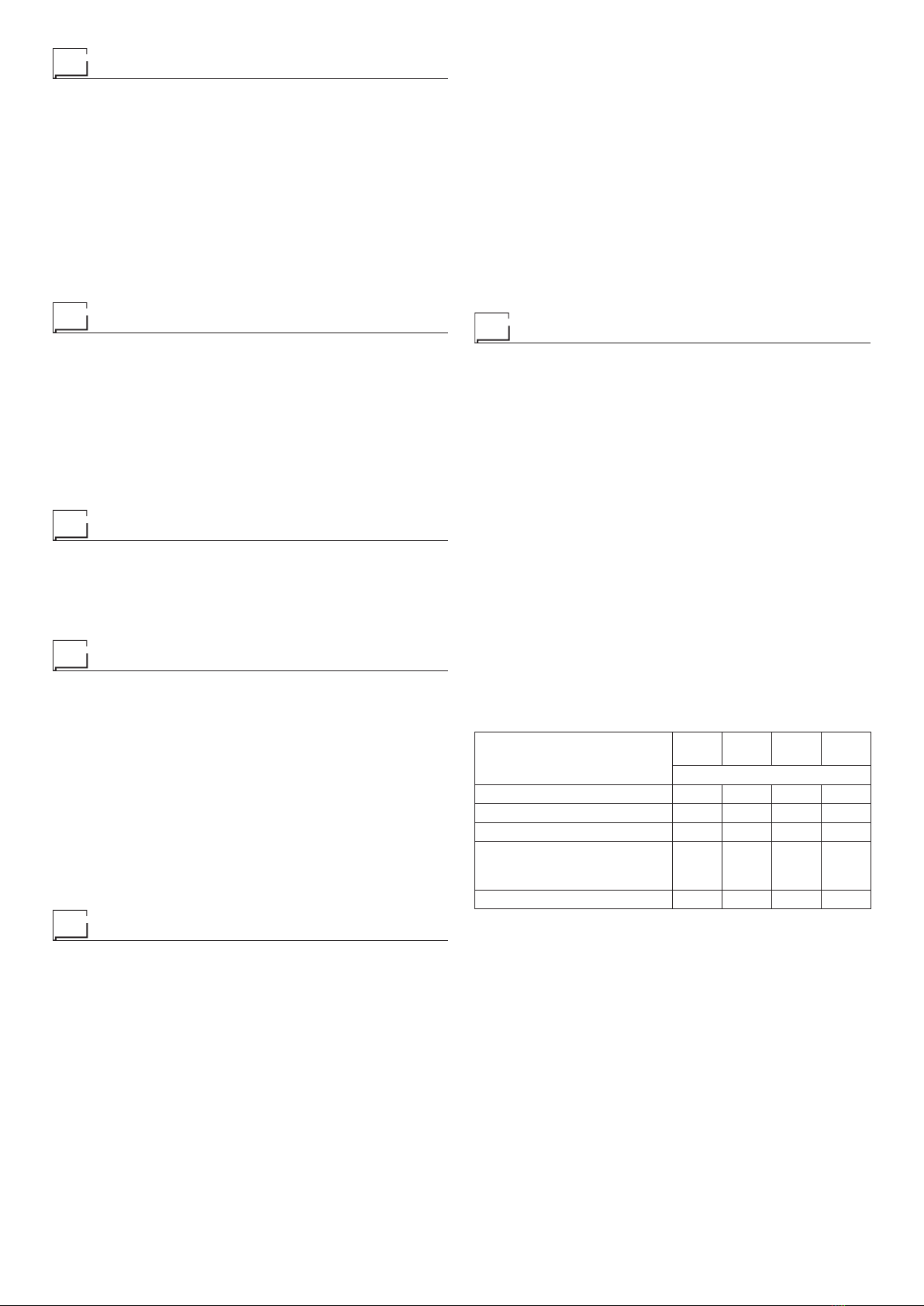
Table 3 shows the capacity values that are recommended for
fuses in the line with delays.
NOTE: Any extensions to the power cable must be of a suita-
ble diameter, and absolutely not of a smaller diameter than the
special cable supplied with the machine.
Table 2
Model
MAXIQ
400
MAXIQ
400w
MAXIQ
500
MAXIQ
500w
MIG-MAG welding
Input power @ I2Max kVA 19 19,5 25,5 26
Delayed fuse (I eff) A32 32 32 32
Duty cycle @ 35% (40°C) A400 400 500 500
Mains cable
Length / Section m
mm2
4,5
4 × 6
4,5
4 × 6
4,5
4 × 6
4,5
4 × 6
Ground cable mm250 50 70 70