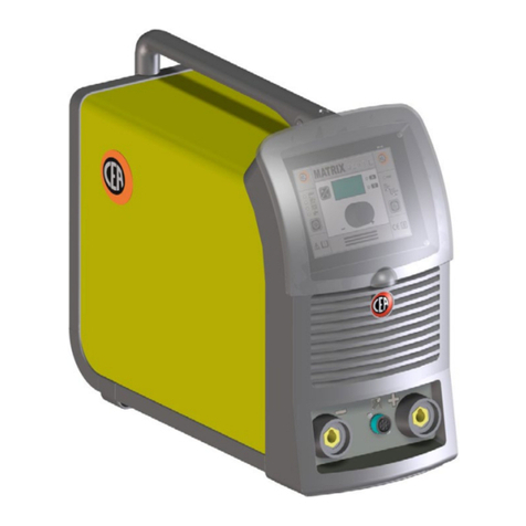
CEA COMPACT 240M User manual

IT
Manuale d’istruzioni
Lista ricambi
2
90-96
L
E
GGE
RE
ATTENTAMENTE
EN
Operator’s manual
Spare parts list
8
90-96
READ
CAREFULLY
FR
Manuel d’instructions
Liste pièce de rechange
14
90-96
L
IRE
ATTENTIVEMENT
DE
Bedienungsanleitung
Ersatzteilliste
20
90-96
SORGFÄLTIG
LESEN
ES
Manual de instrucciones
Lista repuestos
26
90-96
LEER
ATENTAMENTE
NL
Gebruikershandleiding
Onderdelenlijst
32
90-96
EERST GOED
DOORLEZEN
PT
Manual de instruções
Listadepeçasdesubstituição
38
90-97
LER
ATENTEMENTE
DA
Brugerhåndbog
Liste over reservedele
44
90-97
L
ÆS
OMHYGGELIGT
SV
Ågarhandbok
Reservdelslista
50
90-97
LÄS
NOGAS
FI
Omistajankäsikirja
Varaosaluettelo
56
90-97
LUE
HUOLELLISESTI
N
Eierens håndbox
Reservedelliste
62
90-97
LES
NØYE
EL 68
90-97
RU 74
90-97
Dis. n° 1020H650/E Cod. n° 200339 Vers. E 10/2011
CEA COSTRUZIONI ELETTROMECCANICHE ANNETTONI S.p.A.
C
.
so
E.
F
iliberto, 27 - 23900 Lecco - Italy
Tel.
++39.0341.22322 - Fax ++39.0341.422646
Cas. Post. (P.
O.BOX) 205
e-
mail: cea
@ceaweld.com - web: www.ceaweld.com

8
ENGLISH
EN
Introduction 8
Description 8
Technical data 8
Usage limits (IEC 60974-1) 8
How to lift up the system 8
Assembling the welding machine 9
Installation 10
Connection to the electrical supply 10
Gas connection 10
Instructions for use 10
Connection of torch and ground wire 11
Loading wire 11
Welding 11
Aluminium welding 11
Maintenance 12
Possible problems and remedies 12
Troubleshooting table 13
Welding defects 13
Wiring diagram 80
Key to the electrical diagram 81
Colour key 84
Adjustment of electronic PCB 85
Meaning of graphic symbols on machine 86
Meaning of graphic symbols on rating plate 88
Spare parts list 90-93
Entrainment mechanism 94
Drive mechanism 95
Ordering spare parts 96
Description
Semiautomatic single-phase continuous wire welder with switch
adjustments and incorporated feeder, suitable for use with a
gas mixture or CO
2
and with cored wires with and without gas;
suitable for use in medium carpentry and body shops, in agri-
culture and for maintenance.
The main features of
COMPACT 240M
welders are:
•
Exceptional welding characteristics with all materials as a re-
sult of inductance levelling.
• Excellent welding performance on thin metal sheets.
•
Provided with standard gas cylinder trolley with sturdy wheels
to facilitate movement.
•
Free-standing metal structure with front panel in special
shockproof fibre.
• Tough handle for ease of movement.
•
Adequate internal space for conveniently storing metal spools
(Max 300 mm - Max 20 kg).
• Euro torch connection.
•
42 V D.C. geared motor with electronic control of wire speed.
• 2 roll wire drawing unit.
• Agas solenoid valve.
• Switch for selecting 2-step and 4-step modes.
• Potentiometer for the wire speed adjustment.
• Potentiometer for “Burn back” with external adjustment.
• Potentiometer for motor start-up adjustment.
• Potentiometer with switch for adjusting spot-welding times.
Technical data
The technical data for this equipment is summarized in the ta-
ble 1.
Usage limits (IEC 60974-1)
The use of a welder is typicallydiscontinuous, in that it is made
up of effective work periods (welding) and rest periods (for the
positioning of parts, the replacement of wire andunderflushing
operations etc). This welding machine is dimensioned to supply
I2max nominal current (250A), in complete safety, for a work
period amounting to (20%) of total usage time.The regulations
in force establish the total usage time to be 10 minutes. If the
permitted work cycle time is exceeded, an overheat cut-off oc-
curs to protect the components around the welder from dan-
gerous overheating. The yellow thermostat LED located on the
machine rack panel lights up when the overheating protection
trips. After several minutes the overheat cut-off rearms auto-
matically (yellow LED off) and the welder is ready for use again.
How to lift up the system
Before lifting the unit, open the bag containing the eyebolts (at-
tached to machine),remove the two eyebolts complete with fi-
bre washers and mount them on the upper part of the cover.
IMPORTANT:
Only lift the unit using the two eyebolts.
The wire-feeder has a handle and a hook so that it can be
hung up.
NOTE:
The lifting and transporting devices conform with Eu-
ropean regulations. Do not use other equipment to lift or trans-
port the feeder.
Introduction
Thank you for purchasing one of our products. Please read in-
structions on use in this manual as well as the safety rules
given in the attached booklet and follow them carefully to get
the best performance from the plant and be sure that the parts
have the longest service life possible. In the interest of custom-
ers, you are recommended to have maintenance and, where
necessary, repairs carried out by the workshops of our service
organisation, since they have suitable equipment and specially
trained personnel available.All our machinery and systems are
subject to continual development. We must therefore reserve
the right to modify their construction and properties.

9
Assembling the welding machine
The standard composition of this welding installation consists
of:
•
COMPACT 240M
generator.
• Ground lead integrated with the machine 3 m long.
The supply also includes the rear wheels for moving the weld-
er, a chain for securing the gas cylinder to the cylinder trolley,
a handle for moving the machine by hand and two eyebolts for
lifting the machine.
Perform the following operations before using the machine:
•
Remove the welding generator and all relative accessories
and components from the packaging.
•
Check that the welding apparatus is in good condition, other-
wise immediately inform the retailer or distributor.
•
Check that all ventilation grilles are open and that no objects
obstruct the free passage of air.
• Assemble the machine as shown in figure A.
Table 1
Model
COMPACT
240M
Single-phase power supply 50/60 Hz
V 230
Mains supply: Z
max
(*)
Power input @ I
2
Max
kVA 11,9
Delayed fuse (I
2
@ 60%)
A25
Powerfactor/cos
0,96
Maximum efficiency degree
0,58
Open circuit voltage (max)
V22÷50
of switch positions
7
Current range
A 50 ÷ 250
Duty cycle @ 100% (40
°
C)
A110
Duty cycle @ 60% (40
°
C)
A 150
Duty cycle @ 35% (40
°
C)
A 200
Duty cycle @ 20% (40
°
C)
250
Wire diameter
mm 0,6 ÷ 1,2
Standards
IEC 60974-1
IEC 60974-10
Insulation class
IP 23 S
Protection class
H
Dimensions
mm 860-540-790
Weight
kg 59
(*) IMPORTANT:
•
This plant meets the requirements laid down in the EN/IEC 61000-
3-12 standard on harmonic currents.
•
This system, tested according to EN/IEC 61000-3-3, meets the re-
quirements of EN/IEC 61000-3-11.
FIG. A
2000H917

10
Installation
Select the location of the machine to ensure satisfactory and
reliable service. Before installing the welding set the user must
take into account possible electromagnetic problems of the
working area. In particular, we suggest installing the equip-
ment away from:
• Signalling, control and telephone cables.
• Radiotelevision transmitters and receivers.
• Computers or controlling and measuring instrument.
• Safety and protection devices.
The welder must not be rested on a slant of more than 10°.
These welding machines are cooled through air forced-circula-
tion. That is why they must be disposed to facilitate the suction
and the emission of air through the slots of the frame.
The welding unit is characterized by the following classes:
• IP 23 S protection class indicates that the generator can be
used in both interior and exterior environments
.
•
The “S” usage class indicates that the generator can be em-
ployed in environments with a high risk of electrical shocks.
Connection to the electrical supply
Connection of the machine to the user line (electrical cur-
rent) must be performed by qualified personnel.
All connections must be made in conformity with existing regu-
lations while fully respecting the accident-prevention laws (see
CEI 26-10 CENELEC HD 427 regulations).
Before connecting the cutting equipment to the mains sup-
ply, check that the data on the machine plate correspond
to the supply voltage and frequency and its main switch
is on the “O” position.
The connection to the supply, should be made with bipolar ca-
ble which is supplied with the machine, connecting:
• Two wires the supply.
• The third one, yellow-green, to earth.
Connect a suitable plug (3p+t) to the primary cable and fix
to a socket fitted with fuses or automatic switch; the prop-
er earth terminal must be connected to the earth connec-
tor (yellow-green) of the main supply.
Table 2
Model COMPACT
240M
Power input @ I
2
Max
kVA 11,9
Delayed fuse (I
2
@ 60%)
U1=220V-230V-240V
A25
Duty cycle @ 20% (40
°
C)
A 250
Supply connection cable
Length
Section
m
mm
2
4
3×2,5
Gas connection
The units are supplied with a pressure reducer complete with
pressure gauge for adjustment of the pressure of the gas used
in welding (optional). The gas cylinders must be placed on the
rear cylinder-support platform of the welding machine and se-
cured with the chain supplied. They must be installed in a way
that does not interfere with the stability of the welding ma-
chine. The connections between the gas tank, reducer and
gas pipe, from the back panel of the welder, to be made as
showninFig.B.
Open the gas cyclinder and regulate the flowmeter to about
8/12 l/min.
WARNING:
Check that the gas used is compatible with the
material to be welded.
Instructions for use
COMMAND AND CONTROL UNITS (Fig. C-D)
Pos. 1
On/off switch.
Pos. 2 Green LED. This LED lights up when the welder is
powered and ready to work.
Pos. 3
Potentiometer for adjustment of wire speed.
Pos. 4
Welding process switch. It can be set to the following
positions:
•
2strokes-In position the torch key must be
kept pressed down throughout the entire welding
procedure.
•
4 strokes - In position you only have to press
andthenreleasethetorchkeytostartwelding;
press again to stop.
Pos. 5 Potentiometer with switch for regulating the spot weld-
ing time.
Pos. 6 Potentiometer for adjusting “Burn back”.
Pos. 7 Potentiometer for adjusting motor startup (RAMP).
If motor speed is set to maximum, do not select the
ramp under position 2. A motor brush protection de-
vice prevents this from happening.
1234
5
6
7
8
9
FIG. CFIG. B
10
11
FIG. D

11
Pos. 8 Yellow thermostat protection LED. This LED lights up
when the overheating protection trips.You are work-
ing beyond the work cycle (see “Limits of use”). Wait
a few minutes before continuing the welding.
Pos. 9
Welding voltage selection switch.
Pos. 10
Centralized torch connection.
Pos. 11
Snap-in connector for ground line.
Connection of torch and ground wire
• Connect the rear end of the welding torch to the centralized
connector on the front panel (Pos. 10, Fig. D).
•
Insert the ground wire in the snap connectors(Pos. 11,
Fig. D).
Loading wire
•
Open the moving part of the cover and fit the coil (Ø 300
mm) onto the support in such a way that the wire unwinds in
a clockwise direction and centres the projecting reference of
the support with the matching hole in the coil.
•
Thread the end of the wire into the back guide (Pos. 1, Fig. E)
on the drawing mechanism.
•
Raise the idle roller (Pos. 7, Fig. E) to release the roller pres-
sure device (Pos. 5, Fig. E). Check that the diameter of the
wire used is punched on the outer face of the drive roller
(Pos.3,Fig.E).
•
Thread the wire into the wire guide of the centralized attach-
ment (Pos. 4, Fig. E) for a few centimetres. Lower the idle
roll-holder arm making sure the wire goes into the slot of the
drive roll. If necessary, adjust the pressure between the roll-
ers with the screw provided (Pos. 5, Fig. E). The correct pres-
sure is the minimum that does not allow the rollers to skid
on the wire. Excessive pressure will case deformation of the
wire and tangling on the entrance of the sheath; insufficient
pressure can cause irregular welding.
27
1
5
6
3
4
FIG. E
FIG. F
Welding
IMPORTANT:
Before welding,check that the data on the power
source plate correspond to the supply voltage and frequency.
•
Start the welder by pressing the luminous switch (Pos. 1,
Fig. C).
•
The green LED (Pos. 1, Fig. C) lights up to show that the
welder is working and ready to use.
• Turn the welding voltage switch (Pos. 9, Fig. C) to the most
suitablepositionfortheworktoperform.
• Remove the gas-guide and wire-guide nozzles, allowing the
wire to flow freely during loading. Remember that the con-
tact tip must correspond to the wire diameter.
•
Set the wire speed potentiometer on position 3 (Pos. 3,
Fig. C).
• Push the torch push button or the motor check push button
until the wire end comes out from the torch.
• Tighten the contact tip on the torch.
• Attach the correct gas-guide nozzle.
•
Protect the gas-guide nozzle and the wire-guide nozzle of
the torch from sprays of solder.
•
Connect the clamp of the ground lead to the piece to be weld-
ed (see Fig. G).
• The welding machine is ready for welding.
•
To begin welding, approach the point to be welded and press
the button on the torch.
• When you have finished welding, remove the waste, turn off
the machine and close the gas cylinder.
CONTINUOUS WELDING
Select the most suitable wire tension adjustment and speed,
using the respective controls, in function of the type of work to
be carried out. Press the torch button to start the welding cur-
rent and advancement of the wire and perform welding. After
completely the weld, release the torch button to stop the wire
advancement motor immediately. The generator is powered for
a few seconds, long enough to burn the excess wire emerging
from the torch. The gas solenoid remains open to provide for
maintaining an inert atmosphere around the welding zone. This
function is called “Burn Back” and is adjustable. The control cir-
cuit is powered, ready for the next welding cycle.
SPOT WELDING
This type of welding is recommended for repairs in automo-
bile body shops.
• Replace the gas-guide nozzle with the special type for spot
welding (see Fig. F)
•
Set the spot welding time with the potentiometer (Pos. 5,
Fig. C)
•
Select the most suitable tension and speed adjustment, using
the respective controls, in function of the type of work to do.
• Press the gas-guide nozzle perpendicular to the part to be
welded.
•
Press the torch button to start the welding current and ad-
vancement of the wire.
•
At the end of the set spot welding time, the wire stops ad-
vancing automatically.
•
Pressing the torch button again begins a new welding cycle.
• Release the torch button.
Aluminium welding
To weld with aluminum wire proceed as follows:
• Replace the drive rolls with special ones for aluminium wire.
• Use a torch with a 3 m cable and a carbon Teflon sheath.
•
Set the pressure between the drive rollers at the minimum,
by turning the screw provided.
• Use argon gas at a pressure of 1-1,5 bar.
12
Maintenance
IMPORTANT:
Any eventual maintenance must be carried out
by expert, qualified personnel. The guarantee is invalidated if
the final user attempts to repair any damage done to the ma-
chine by himself.
WARNING:
Before carrying out any inspection of the inside of
the generator, disconnect the system from the supply.
GENERATOR
The maintenance of this equipment is limited to the cleaning of
the inside of the frame and periodic inspection of worn cables
or loose connections.At regular intervals disconnect the weld-
er from the mains, take off the cover and use dry compressed
air to remove possible accumulations of dirt and dust. During
this operation do not direct the jet of air onto electronic com-
ponents. Check, that the gas circuit is completely free from im-
purities and that the connections are tight and that there are
no leaks. Carefully check that the electric valve does not leak.
Check the wire feeder rolls periodically and replace them when
wear impairs the regular flow of the wire (slipping etc).
TORCH
The torch is subjected to high temperatures and is also stressed
by traction and torsion. We recommend not to twist the wire and
not to use the torch to pull the welder.As a result of the above
the torch will require frequent maintenance such as:
• Cleaning welding splashes from the gas diffuser so that the
gas flows freely.
• Substitution of the contact point when the hole is deformed.
•
Cleaning of the wire guide liner using trichloroethylene or
specific solvents.
• Check of the insulation and connections of the power cable;
the connections must be in good electrical and mechanical
condition.
REPLACEMENT OF THE ELECTRONIC PCB
Proceed as follows:
•
Open the moving part of the cover on the right-hand side us-
ing the relative bolts.
•
Remove the black fibre board cover by unscrewing the 3
screws with a suitable screwdriver (Fig. H).
• Remove the circuit board connectors.
•
Take the plugsoff the handles located on the front rack panel
and then remove them with a suitable box wrench.
• The circuit board can now be removed and replaced.
• Reverse the procedure to fit the new card.
Possible problems and remedies
The detection of eventual problems and their solution. The pow-
er supply line is the major source of problems. In the event of
a fault proceed as follows:
1) Check the voltage of the supply
.
2) Check the state of the line connection at the plug and the
main switch
.
3) Check that the main fuses are not burnt out or loose
.
4) Check the following for defects:
• The switch and wall outlet that power the machine
• The plug and mains cable
• The welder switch
FIG. G
2000H921
FIG. H
2000H919

13
Troubleshooting table
Problem Cause Remedy
The line fuses burn out and
close the line circuit breaker • Wrong connection • Check and follow the
instructions for connection
• Short circuit on fan motor • Repair or replace the motor
The line fuses burn out when
the torch button is pressed • Short circuit on rectifier • Replace rectifier
• Short circuit on main transformer winding • Replace transformer
The line fuses burn out after
working for some time • Fuses not high enough capacity • Use fuses of adequate capacity
for the line absorption
The welder does not
emit current • Wrong connection • Check and follow the
instructions for connection
• Line fuses burnt out • Find the cause and replace
• Circuit open on welding cables • Check the welding cables for breakage
Welding current unsteady • Variations of voltage on the line • Check the line voltage with a voltmeter
• Section of connecting cables too small • Replace with cables of adequate section
• Loose connections • Check connections to the power mains
and welding circuit and tighten if necessary
Welding defects
Problem Cause Remedy
Porosity (external or internal) • Defective wire • Change wire
• Insufficient gas flow • Adjust flow
• Defective flow meter • Check flow meter
• Defective solenoid • Check
• Wire guide nozzle clogged • Clean nozzle
• Gas flow holes clogged • Clean with jets of air
• Drafts of air • Screen the workplace
Withdrawal cracks • Wire or piece dirty or rusty • Replace wire or clean piece
• Bead too small • Increase current
• Bead too concave • Reduce voltage
• Bead too penetrating • Reduce voltage and current
Lateral incisions • Pass speed too high • Slow down
• Current too low and voltage too high • Increase wire speed and reduce voltage
Excessive splashing • Voltage too high • Adjust voltage
• Wire guide nozzle clogged • Clean nozzle
• Torch tilted too much • Tilt correctly

80
2101E773
IT Schema elettrico
EN Wiring diagram
FR Schéma électrique
DE Schaltplan
ES Esquema eléctrico
NL Elektrisk skema

81
•1 •2 •3 •4 •5 •6 •7 •8 •9 •10 •11 •12 •13
BCL BP BS C CL CR CT D DP EVG F Ib IL
•14 •15 •16 •17 •18 •19 •20 •21 •22 •23 •24 •25 •26
L LA LT MT MV PBB PM PRM PST PT PVF R RS
•27 •28 •29 •30 •31 •32 •33 •34 •35
SE TA TM TMAX TMIN TP TR TT V
IT Legenda schema elettrico
•1 Bobina contattore di linea •2 Bobina primaria •3 Bobina secondaria
•4 Condensatore elettrolitico •5 Contattore di linea •6 Commutatore di
tensione •7 Connettore torcia •8 Diodi •9 Deviatore processo MAN-AUT
•10 Elettrovalvola gas •11 Fusibile •12 Inizio bobina •13 Interruttore di
linea •14 Induttore •15 Lampada spia alimentazione •16 Lampada spia
termostato •17 Motore meccanismo di trascinamento •18 Motore ventilatore
•19 Potenziometro BURN-BACK •20 Morsetto massa •21 Potenziometro
rampa motore •22 Potenziometro puntatura •23 Pulsante torcia •24
Potenziometro velocità filo •25 Resistore •26 Raddrizzatore secondario
•27 Scheda controllo •28 Trasformatore ausiliario •29 Torcia MIG-MAG •30
Trimmer regolazione velocità massima •31 Trimmer regolazione velocità
minima •32 Trasformatore principale •33 Termostato raddrizzatore •34
Termostato trasformatore
•35
Varistore raddrizzatore
EN Key to the electrical diagram
•1 Line contactor coil •2 Primary coil •3 Secondary coil •4 Electrolytic
condenser
•5
Line contact
•6
Voltage switch
•7
Torch connector
•8
Diodes
•9
MAN-AUT mode switch
•10
Gas solenoid valve
•11
Fuse
•12
Coil start
•13 Supply switch •14 Inductor •15 Supply signal light •16 Thermostat
intervention indicator •17 Feeding mechanism motor •18 Fan motor •19
BURN-BACK potentiometer •20 Earth terminal •21 Initial motor speed
potentiometer •22 Spotwelding potentiometer •23 Torch button •24 Wire
speed potentiometer •25 Resistor •26 Secondary rectifier •27 Control
PCB •28 Auxiliary transformer •29 MIG-MAG torch •30 Maximum speed
adjustment trimmer •31 Minimum speed adjustment trimmer •32 Main
transformer •33 Rectifier thermostat •34 Transformer thermostat •35
Varistor rectifier
FR Légende schéma électrique
•1 Bobine contacteur de ligne •2 Bobine primaire •3 Bobine secondaire
•4 Condensateur électrolytique •5 Contacteur de ligne •6 Commutateur
de tension •7 Connecteur torche •8 Diodes •9 Déviateur fonctionnement
MAN-AUT •10 Electrovanne du gaz •11 Fusible •12 Début bobine •13
Interrupteur de ligne •14 Inducteur •15 Voyant alimentation de réseau •16
Lampe intervention thermostat •17 Moteur mécanisme d’entraînement •18
Moteur ventilateur •19 Potentiomètre BURN-BACK •20 Borne masse •21
Potentiomètre rampe moteur •22 Potentiomètre soudure par points •23
Bouton poussoir de la torche •24 Potentiomètre vitesse du fil •25 Résistance
•26 Redresseur primaire •27 Fiche de contrôle •28 Transformateur auxiliaire
•29 Torche MIG-MAG •30 Trimmer réglage vitesse maximale •31 Trimmer
réglage vitesse minimale •32 Transformateur principal •33 Thermostat
redresseur •34 Thermostat transformateur •35 Varistore redresseur
DE Schaltplan-Legende
•1 Bobine von dem Leistungkontaktgeber •2 Primärspule •3 Sekundärspule
•4 Elektrolytkondensator •5 Leistungkontaktgeber •6 Spannungsumschalter
•7 Brennerverbinder •8 Dioden •9 Wechselschalter für Verfahren
MAN-AUT •10 Gaselektroventil •11 Sicherung •12 Spuleneinsatz •13
Leitungschalter •14 Drosselspule •15 Anzeigelampe Speisung •16
Kontrolleuchte Thermostateinschaltung •17 Mechanismuszugmotor
•18 Lüftermotor •19 BURN-BACK-Potentiometer •20 Masseanschluss
•21 Potentiometer Motorrampe •22 Potentiometer Punktschweißen •23
Brennerschalter •24 Potentiometer Drahtgeschwindigkeit •25 Widerstand
•26 Sekundärer Gleichrichter •27 Kontrollkarte •28 Hilfstransformator •29
MIG-MAG Brenner •30 Trimmer Einstellung Höchstgeschwindigkeit •31
Trimmer Einstellung Mindestgeschwindigkeit •32 Haupttransformator
•33 Thermostat Gleichrichter •34 Transformator-Thermostat •35 Varistor
Gleichrichter
ES Leyenda esquema eléctrico
•1 Bobina del contactor de línea •2 Bobina primaria •3 Bobina secundaria •4
Condensador electrolítico •5 Contactor de línea •6 Commutador de tensión
•7 Conector antorcha •8 Diodos •9 Desviador proceso MAN-AUT •10
Electroválvula gas •11 Fusible •12 Inicio bobina •13 Interruptor de línea •14
Inductor •15 Lámpara de alimentación de red •16 Lámpara de intervención
termostato •17 Motor mecanismo de arrastre •18 Motor ventilador •19
Potenciómetro BURN-BACK •20 Borne masa •21 Potenciómetro rampa
motor •22 Potenciómetro soldadura por puntos •23 Pulsador antorcha •24
Potenciómetro velocidad hilo •25 Resistor •26 Enderezador secundario •27
Placadecontrol•28 Transformador auxiliar •29 Antorcha MIG-MAG •30
Trimmer regulación velocidad máxima •31 Trimmer regulación velocidad
mínima •32 Transformador principal •33 Termóstato rectificador •34
Termostato transformador •35 Varistor rectificador
NL Legenda elektrisch schema
•1 Bobine contactor op lijn •2 Hoofd-bobine •3 Secundaire bobine •4
Electrolytische condensator •5 Contactor van de lijn •6 Omschakelaar
spanning •7 Stik til svejsebrænder •8 Weerstanden •9 Keerschot proces
handmatig - automatisch (MAN-AUT) •10 Elektroventil for gas •11 Zekering
•12 Begin spoel •13 Lijnonderbreker •14 Inductor •15 Stekker lijngvoeding
•16 Lampje thermostaatinschakeling •17 Motor aanvoermechanisme
•18 Ventilatormotor •19 Potentiometer BURN-BACK •20 Massaklem
•21 Potentiometer optreksnelheid motor •22 Potentiometer hechting •23
Toortsknop •24 Potentiometer draadsnelheid •25 Elektrische weerstand •26
Secundaire gelijkrichter •27 Controlekaart •28 Hulptransformator •29 MIG-
MAG toorts •30 Trimmer regeling maximale snelheid •31 Trimmer regeling
minimale snelheid •32 Hoofdtransformator •33 Thermostaat gelijkrichter
•34 Thermostaat transformator •35 Varistore gelijkriehter

82
PT Esquema eléctrico
DA Forbindelsesdiagram
SV Elektiska schema
FI Sähkökaavio
NElektriske skjema
EL
RU
2101E773

83
PT Legenda do esquema eléctrico
•1 Bobina contactor linha •2 Bobina primária •3 Bobina secundária •4
Condensador electrolítico •5 Contactor linha •6 Comutador de tensão
•7 Conector da tocha •8 Diodos •9 Desviador de processo MAN-AUT
•10 Eletro válvula de gás •11 Fusível •12 Início bobina •13 Interruptor
de alimentação •14 Indutor •15 Sinalizador luminoso de alimentação de
rede •16 Lâmpada de intervençâo do termostato •17 Motor mecanismo
de arrastamento •18 Motor ventilador •19 Poten-ciómetro BURN-BACK
•20 Borne massa •21 Potenciómetro rampa do motor •22 Potenciômetro
soldagem por pontos •23 Botãodatocha•24 Potenciómetro de velocidade
do fio •25 Resistor •26 Rectificador secundário •27 Placadecontrolo•28
Transformador auxiliar •29 Tocha MIG-MAG •30 Trimmer regulação da
velocidade máxima •31 Trimmer regulação da velocidade mínima •32
Transformador principal •33 Termostato rectificador •34 Termostato do
transformador •35 Varistor retificador
DA Nøgle til forbindelsesdiagrammet
•1 Spole til liniekontaktor •2 Primærspole •3 Sekundærspole •4 Elektrolytisk
kondensator •5 Liniekontaktor •6 Kommutator for spænding •7 Stik til
svejsebrænder •8 Dioder •9 Omskifter MAN-AUT •10 Elektroventil for
gas •11 Sikring •12 Spolens start •13 Omkobler •14 Induktansspole •15
Lysdiode til elektrisk forsyning •16 Lampe for udløsning af termostat
•17 Motor fremførermekanisme •18 Ventileret motor •19 BURN-BACK-
potentiometer •20 Klemme til jordledning •21 Styrkeregulering af motorens
tæn-ding •22 Potentiometer for trådhastighed •23 Knap på svejsebrænder
•24 Potentiometer for svejsetrådens hastighed •25 Elektrisk modstand •26
Sekundær ensretter •27 Kontrolkortet •28 Hjæipetransformer •29 MIG-
MAG brænder •30 Kondensator til regulering af maksimumhastighed •31
Kondensator til regulering af minimumhastighed •32 Hovedtransformator
•33 Transformator-ensretter •34 Termostat for transformator •35 Varistor
strømensretter
SV Förklaring av elektriskt schema
•1 Linjekontaktorspole •2 Primärspole •3 Sekundärspole •4 Elektrolystisk
kondensator •5 Linjekontakt •6 Spänningströmbrytare •7 Intag för
skärbrännaren •8 Dioder •9 Processväljare MAN-AUT •10 Elektromagnetisk
gasventil •11 Säkring •12 Startspolar •13 Linjeströmbrytare •14 Induktor •15
Indicator näkström •16 Lampa för termostat •17 Motor till dragmekanism •18
Ventilationsmotor •19 Potentiometer BURN-BACK •20 Jordledningsklämma
•21 Potentiometer motorramp •22 Potentiometer för punktsvetsning •23
Tryckknapp för skärbrännaren •24 Potentiometer trådhastighet •25 Resistor
•26 Sekundär likriktare •27 Styrkretskortet •28 Reservtransformator •29
Fackla MIG-MAG •30 Trimmer för max. hastighetsreglering •31 Trimmer
för min. hastighetsreglering •32 Huvudtransformator •33 Likriktartermostat
•34 Termostat för transformator •35 Växlare för likriktare
FI Sähkökaavion merkinnät
•1 Linjapistoke •2 Ensiökäämi •3 Toisiokäämi •4 Elektrolyyttinen
kondensaattori •5 Pistotulppa •6 Virtakatkaisija •7 Polttimen liitin •8 Diodit •9
Prosessin vaihtokytkin MAN-AUT •10 Kaasun solenoidiventtiili •11 Sulake
•12 Käämin alku •13 Pääkatkaisija •14 Induktori •15 Verkkovirran mekkivalo
•16 Termostaatin laukeamisen lamppu •17 Vetomekanismin moottori •18
Tuuletettu moottori •19 Potentiometri BURN-BACK •20 Maadoituspuristin
•21 Moottorirampin potentiometri •22 Pistehitsauksen potentiometri •23
Polttimen painike •24 Langan nopeuden potentiometri •25 Resistori •26
Toisiotasasuuntain •27 Valvontakortti •28 Varamuuntaja •29 Juottulamppu
MIG-MAG •30 Maksiminopeuden säätötrimmeri •31 Miniminopeuden
säätötrimmeri •32 Päämuunnin •33 Tasasuuntaajan termostaatti •34
Muuntimen termostaatti •35 Tasasuuntaimen varistori
•1 •2 •3 •4 •5 •6 •7 •8 •9 •10 •11 •12 •13
BCL BP BS C CL CR CT D DP EVG F Ib IL
•14 •15 •16 •17 •18 •19 •20 •21 •22 •23 •24 •25 •26
L LA LT MT MV PBB PM PRM PST PT PVF R RS
•27 •28 •29 •30 •31 •32 •33 •34 •35
SE TA TM TMAX TMIN TP TR TT V
NTegnforklaring av elektrisk skjema
•1 Spole kontaktor for linjen •2 Primærspole •3 Sekundærspole •4
Elektrolyttkondensator •5 Kontaktor for linjen •6 Kommutator spenning
•7 Brennerkopling •8 Dioder •9 Prosessbryter MAN-AUT •10 Elektronisk
gassventil •11 Sikring •12 Startspole •13 Linjebryter •14 Induktor •15
Varsellampe matenettet •16 Varsellampe for tilkopling termostat •17
Motor trekkemekanisme •18 Motor ventilator •19 Spenningsmåler
BURN-BACK •20 Masseklemme •21 Spenningsmåler motorrampe
(starter) •22 Spenningsmåler punktsveising •23 Brennerknapp •24
Punktsveisepotensiometer •25 Motstand •26 Sekundær ensretter
•27 Kontrollkort •28 Hjelpetransformator •29 MIG-MAG brenner •30
Trimmer regulering av maksimumshastighet •31 Trimmer regulering av
minimumshastighet •32 Hovedtransformator •33 Likerettertermostat •34
Termostat transformator •35 Likerettervaristor
EL
•1 •2 •3 •4
•5 •6
•7 •8 •9
-(MAN-AUT) •10 ( )
•11 •12 •13 •14
•15 •16
•17 •18
•19 BURN-BACK •20 •21
•22 •23
•24 •25 •26
•27 •28
•29 MIG-MAG •30 Trimmer
•31 Trimmer •32 •33
•34 •35
RU
•1 •2 •3
•4 •5
•6 •7 •8
•9 MAN-AUT •10
•11 •12
•13 •14 •15 •16
•17
•18 •19
«BURN-BACK»
•20 •21
•22 •23
•24 •25
•26 •27
•28 •29 -•30
•31
•32
•33 •34
•35

84
IT Legenda colori
Ar Arancio
Az Azzurro
Bc Bianco
Bl Blu
GV Giallo Verde
Gg Grigio
Gl Giallo
Mr Marrone
Nr Nero
Ro Rosa
Rs Rosso
Vd Verde
Vl Viola
EN Colour key
Ar Orange
Az Sky Blue
Bc White
Bl Blue
GV Yellow Green
Gg Grey
Gl Yellow
Mr Brown
Nr Black
Ro Pink
Rs Red
Vd Green
Vl Violet
FR Légende couleurs
Ar Orange
Az Bleu Clair
Bc Blanc
Bl Bleu
GV Jaune Vert
Gg Gris
Gl Jaune
Mr Marron
Nr Noir
Ro Rose
Rs Rouge
Vd Vert
Vl Violet
DE Farbenlegende
Ar Orange
Az Hellblau
Bc Weiß
Bl Blau
GV Gelb Grün
Gg Grau
Gl Gelb
Mr Braun
Nr Schwarz
Ro Rosa
Rs Rot
Vd Grün
Vl Violett
ES Leyenda colores
Ar Anaranjado
Az Azul
Bc Blanco
Bl Azul
GV Amarillo Verde
Gg Gris
Gl Amarillo
Mr Marrón
Nr Negro
Ro Rosa
Rs Rojo
Vd Verde
Vl Violeta
NL Kleurenlegenda
Ar Oranje
Az Blauw
Bc Wit
Bl Donkerblauw
GV Geel Groen
Gg Grijs
Gl Geel
Mr Bruin
Nr Zwart
Ro Roze
Rs Rood
Vd Groen
Vl Paars
PT Legenda cores
Ar Laranja
Az Azul
Bc Branco
Bl Azul-marinho
GV Amarelo Verde
Gg Cinza
Gl Amarelo
Mr Castanho
Nr Preto
Ro Cor-de-rosa
Rs Vermelho
Vd Verde
Vl Roxo
DA Nøgle til farver
Ar Orange
Az Lyseblå
Bc Hvid
Bl Blå
GV Gul Grøn
Gg Grå
Gl Gul
Mr Brun
Nr Sortt
Ro Rosa
Rs Rød
Vd Grøn
Vl Lilla
SV Färgförklaring
Ar Orange
Az Ljusblå
Bc Vit
Bl Blå
GV Gul Grön
Gg Grå
Gl Gul
Mr Brun
Nr Svart
Ro Rosa
Rs Röd
Vd Grön
Vl Lila
FI Väriselitykset
Ar Oranssi
Az Vaaleansininen
Bc Valkoinen
Bl Sininen
GV Keltainen Vihreä
Gg Harmaa
Gl Keltainen
Mr Ruskea
Nr Musta
Ro Vaaleanpunainen
Rs Punainen
Vd Vihreä
Vl Violetti
NFargeforklaring
Ar Oransje
Az Nyseblå
Bc Hvit
Bl Blå
GV Gul Grønn
Gg Grå
Gl Gul
Mr Brun
Nr Svart
Ro Rosa
Rs Rød
Vd Grønn
Vl Lilla
EL
Ar
Az
Bc
Bl
GV
Gg
Gl
Mr
Nr
Ro
Rs
Vd
Vl
RU
Ar
Az
Bc
Bl
GV
Gg
Gl
Mr
Nr
Ro
Rs
Vd
Vl

85
IT Regolazione scheda elettronica
Trimmer RT1:
Regolazione velocità minima filo
Trimmer RT2:
Regolazione velocità massima filo
NOTA:
I trimmer possono essere regolati agendo sulla scheda
elettronica dall'esterno mediante un cacciavite aprendo il
coperchio parte mobile e smontando la copertura, in fibra nera,
di protezione scheda elettronica.
EN Adjustment of electronic circuit board
Trimmer RT1:
Minimum wire speed adjustment
Trimmer RT2:
Maximum wire speed adjustment
NOTE:
The trimmers can be adjusted from the electronic circuit
board. Open the mobile part of the cover with a screwdriver
and remove the layer of black fibre covering the circuit board.
FR Réglage fiche électronique
Trimmer RT1:
Réglage vitesse minimale fil
Trimmer RT2:
Réglage vitesse maximale fil
NOTE:
Les trimmers peuvent être réglés en agissant de
l'extérieur sur la carte électronique avecun tournevis en ouvrant
le couvercle de la partie mobile et en démontant la couverture,
en fibre noire, de protection de la carte électronique.
DE Einstellung der Elektronikkarte
Trimmer RT1:
Einstellung der Drahtmindestgeschwindigkeit
Trimmer RT2:
Einstellung der Drahthöchstgeschwindigkeit
NOTE:
Die Trimmer können durch Eingriff an der Elektronikkarte
von außen durch einen Schraubenzieher eingestellt werdne,
indem der bewegliche Deckelteil geöffnet wird und die
Schutzabdeckung der Elektronikkarte aus schwarzer Faser
abmontiert wird.
ES Regulación tarjeta electrónica
Trimmer RT1:
Regulación de la velocidad mínima del hilo
Trimmer RT2:
Regulación de la velocidad máxima del hilo
NOTA:
Los trimmer se pueden regular manipulando desde
fuera la tarjeta electrónica, abriendo mediante un destornillador
la tapadera de la parte móvil y desmontando la cubierta, de
fibra negra, que protege la tarjeta electrónica.
NL Afstellen elektronische kaart
Trimmer RT1:
Regeling minimale snelheid van de draad
Trimmer RT2:
Regeling maximale snelheid van de draad
OPMERKING:
De trimmer kan geregeld worden door in te
werken op de elektronische fiche van buitenuit aan de hand
van een schroevedraaier. Dit door als volgt tewerk te gaan:
het beweeglijk deel van het deksel openen en de bedekking,
in zwarte vezel demonteren van de bescherming elektronische
fiche.
PT Regulação da placa electrónica
Trimmer RT1:
Regulação da velocidade mínima do fio
Trimmer RT2:
Regulação da velocidade máxima do fio
NOTA:
È possível regular os trimmer agindo no cartão
electrônico do exterior mediante uma chave de parafusos,
abrindo a tampa da parte móvel e desmontando o revestimento
de fibra preta que protege o cartão electrônico.
DA Justering af elektronisk kort
Trimmer RT1:
Indstilling af trådens minimumshastighed
Trimmer RT2:
Indstilling af trådens maksimumhastighed
BEMÆRK:
Kondensatorerne kan indstilles på det elektroniske
kredsløbskort ved at åbne den aftagelige del af låget med en
skruetrækker og derefter aftage dækpladen i sort fiber, der skal
beskytte det elektroniske kredsløbskort.
SV Reglering av kretskortet
Trimmer RT1:
Reglering av trådens minimihastighet
Trimmer RT2:
Reglering av trådens maximihastighet
OBSERVERA:
Trimmern kan regleras genom att justera det
elektroniska kortet från utsidan med hjälp av en skruvmejsel
genom att öppna den rörliga delens lock och ta loss det
elektroniska kortets svarta fiberskydd.
FI Elektronisen kortin säätäminen
Trimmer RT1:
Langan miniminopeuden säätö
Trimmer RT2:
Langan maksiminopeuden säätö
HUOMIO:
Trimmereitä voidaan säätää ulkopuolelta säätämällä
sähköistä korttia ruuvitaltalla.Avaa liikkuvan osan kansi ja irrota
elektronisen kortin mustaa kuitua oleva suojus.
NRegulering av det elektroniske kortet
Trimmer RT1:
Regulering av minimumshastighet på tråden
Trimmer RT2:
Regulering av maksimumshastighet på tråden
MERKNAD:
Trimmerene kan reguleres ved å skru på det
elektroniske kortet utenifra ved hjelp av en skrutrekker for å
åpne dekslet på enheten og demontere beskyttelsesdekket, i
sort fiber, til det elektroniske kortet.
EL
Trimmer RT1:
Trimmer RT2:
:
trimmer
.
RU
RT1:
.
RT2:
.
:
,
.
,
.

86
1 2 3 4 5 6
V
t
7
8 9 10 11 12 13 14
IT Significato dei simboli grafici
riportati sulla macchina
•1 Intervento termostato •2 Regolazione velocità filo •3 Regolazione tempo
di puntatura •4 Terra di protezione •5 Pericolo, organi in movimento •6
Tensione pericolosa •7 Regolazione rampa motore •8 Regolazione tempo
di burn-back •9 Divieto utilizzo guanti •10Attenzione! •11 Prima di utilizzare
l’impianto è necessario leggere attentamente le istruzioni contenute in
questo manuale
•12
Tensione di rete
•13
Funzione 4 tempi
•14
Funzione
2tempi
EN Meaning of graphic symbols on machine
•1 Thermostat intervention •2 Wire speed adjustment •3 Spot welding time
adjustment •4 Ground protection •5 Danger: moving parts •6 Hazardous
voltage •7 Motor capacity regulation •8 Burn-back time adjustment •9 It is
forbidden to use gloves •10 Warning! •11 Before using the equipment you
should carefully read the instructions included in this manual •12 Mains
supply voltage •13 4 strokes function •14 2 strokes function
FR Interprétation des symboles graphiques
reportés sur la machine
•1 Intervention thermostat •2 Réglage de la vitesse du fil •3 Réglage
temps de pointage •4 Mise à la terre de protection •5 Danger, partes en
mouvement •6 Tension dangereuse •7 Réglage rampe moteur •8 Réglage
durée de burn-back •9 Interdiction d’utiliser des gants •10 Attention! •11
Avant d’utiliser l’installation il est nécessaire de lire avec attention les
instructions qui se trouvent dans ce manuel •12 Tension de réseau •13 4
temps •14 2 temps
DE Bedeutung der grafischen
Symbole auf der Maschine
•1
Thermostateinschaltung
•2
EinstellungderDrahtvorschubgeschwindigkeit
•3 Einstellung Heftschweißzeit •4 Schutzerde •5 Achtung, bewegliche
Teile •6 Gefährliche Spannung •7 Einstellung Motorrampe •8 Einstellung
burn-back-Zeit •9 Keine Handschuhe benützen •10 Achtung! •11 Vor der
Anwendung derAnlage sind die Gebrauchsanweisungen des vorliegenden
Handbuches sorgfältig zu lesen •12 Netzspannung •13 4Takt•14 2 Takt
ES Significado de los símbolos gráficos
referidos en la máquina
•1 Intervención termostato •2 Regulación de la velocidad alambre •3
Regulación tiempo de punteado •4 Tierra de protección •5 Peligro,
partes en movimiento •6 Tensión peligrosa •7 Regulación rampa motor
•8 Regulación tiempo de burn-back •9 Está prohibido usar guantes •10
Atención! •11Antes de utilizar la instalación, es necesario leer atentamente
las instrucciones contenidas en este manual •12 Tensióndelared•13 4
tiempos •14 2 tiempos
NL Betekenis grafische symbolen op
het apparaat weergeven
•1 Thermostaat inschakeling •2 Regeling draadsnelheid •3 Regeling
puntlastijd •4 Beschermingsaarding •5 Gevaar, bewegende delen •6
Gevaarlijke spanning •7 Instelling optreksnelheid motor •8 Instelling burn-
back-tijd •9 Verboden handschoenen te gebruiken •10 Let op! •11 Voordat
de aansluiting in gebruik genomen wordt is het noodzakelijk om aandachtig
de gebruiksaanwijzing in deze handleiding te lezen •12 Netspanning •13
4tijden•14 2 tijden

87
1 2 3 4 5 6
V
t
7
8 9 10 11 12 13 14
PT Significado dos símbolos gráficos
relatados na máquina
•1 Intervenção do termostato •2 Regulação de velocidad do fio •3
Regulação do tempo de solda por pontos •4 Terra de protecção •5 Perigo,
partes em movimento •6 Tensão perigosa •7 Regulação da rampa do motor
•8 Regulação do tempo de burn-back •9 Proibido utilizar luvas •10Atenção!
•11Antes de usar a instalação é necessário ler atentamente as instruções
contidas neste manual •12 Tensão de rede •13 4tempos•14 2tempos
DA Betydning af symboler på apparat
•1 Termostat udløst •2 Justering af trådens hastighed •3 Justering
af punktsvejsetid •4 Jordbeskyttelse •5 Fare, dele i bevægelse •6
Farlig spænding •7 Regulering af motorens tænding •8 Burn-back-
hastighedsregulering •9 Forbud mod at anvende handsker •10 Giv act!
•11 Inden dette anlæg tages i brug er det rådeligt at læse omhyggeligt
igennem oplysninger som denne håndbog indeholder •12 Netspænding
•13 4 hastigheder •14 2 hastigheder
SV Förklaring av grafiska symboler på apparaten
•1 Termostat •2 Reglering af trådens hastighet •3 Inställning
punktsvetsningstid •4 Skyddsjord •5 Giv akt! Maskindelar i gång •6 Farlig
spänning •7 Justering av motorramp •8 Justering av burn-back-tid •9
Förbjudet att använda handskar •10 Observera! •11 Innan ibruktagandet
av anläggningen är det viktigt att uppmärksamt läsa instruktionerna i denna
manual •12 Nätstyrka •13 4faser•14 2 faser
FI Laitteessa olevien symbolien selitykset
•1 Termostaatin keskeytys •2 Langan nopeuden sää dön •3 Pistehitsauksen
ajan sää tö •4 Suojamaadoitus •5 Vaara, liikkuvia osia •6 Vaarallinen jännite
•7 Moottorirampin säätö •8 Burn-back-ajan säätö •9 Ei saa käyttää käsineitä
•10 Huomio! •11 Før du tar sveisemaski-nen i bruk, skal du lese nøye
igjennom instruksene i denne håndboken •12 Verkkovoimakkuus •13
4-tahtinen toiminto •14 2-tahtinen toiminto
NTegnforklaring av de grafiske
symbolene på maskinen
•1 Termostatinngrep •2 Regulering af trådens hastighet •3 Tidsregulering
punktsveising •4 Beskyttelsesjording •5 Gi akt! Maskindeler i gang •6
Høyspenning •7 Regulering motorrampe •8 Regulering burn-back tid
•9 Forbudt å bruke hansker •10 Merk! •11 Før du tar sveisemaskinen i
bruk, skal du lese nøye igjennom instruksene i denne håndboken •12
Nettspenning •13 4-taktsfunksjon •14 2-taktsfunksjon
EL
•1 •2 •3
•4
•5 K , •6 •7
•8 BURN-BACK •9
•10 !•11
, ,
•12 •13 4•14
2
RU Significato dei simboli grafici
riportati sulla macchina
•1 •2
•3
•4
,•5 •6 ,
•7 •8
•9 BURN-BACK
•10 •11
!
•12
,
•13 •14 4-
2-

88
IT Significato dei simboli grafici
riportati sulla targa dati
•1 Nome e indirizzo costruttore •2 Denominazione impianto •3
Trasformatore raddrizzatore •4 Corrente continua di saldatura •5 Saldatura
MIG-MAG •6 Saldatrice utilizzabile in ambienti con rischio accresciuto di
scosse elettriche •7 Tensione a vuoto secondaria •8 Alimentazione di rete
e numero delle fasi •9 Frequenza nominale di rete •10 Valore nominale
tensione di alimentazione •11 Raffreddamento ad aria forzata •12 Classe
di isolamento •13 Grado di protezione dell’involucro •14 Prodotto atto a
circolare liberamente nella Comunità Europea •15 Smaltimento speciale
•16 Massimo valore della corrente nominale di alimentazione•17 Massimo
valore della corrente effettiva di alimentazione •18 Tensione nominale del
carico •19 Corrente nominale di saldatura •20 Rapporto di intermittenza
•21 Minima e massima corrente e tensione di saldatura •22 Normativa di
riferimento •23 Numero di matricola
EN Meaning of graphic symbols on rating plate
•1 Name and address of manufacturer •2 Name of system •3 Transformer
rectifier •4 Continuous welding current •5 MIG-MAG welding •6 Welder
usable in environments with enhanced risk of electroshock •7 Secondary
no-load voltage •8 Mains power supply and number of phases •9 Nominal
supply frequency •10 Nominal value of supply voltage •11 Forced air cooling
•12 Insulation class •13 Degree of protection of casing •14 Product suitable
for free circulation in the European Community •15 Special disposal •16
Maximum value of rated supply current •17 Maximum value of effective
input current •18 Nominal load voltage •19 Nominal welding current •20
Duty cycle •21 Mimimum and maximum current and welding voltage •22
Reference standards •23 Serial number
FR Interprétation des symboles graphiques
sur la plaque de données
•1 Nom et adresse du fabricant •2 Dénomination de l’installation •3
Transformateur-redresseur •4 Courant de soudure continu •5 Soudure
MIG-MAG •6 Soudeuse pouvant être utilisée dans un environnement
avec risque croissant de décharges électriques •7 Tension secondaire
àvide•8 Alimentation de réseau et numéro des phases •9 Fréquence
nominale d’alimentation •10 Valeur nominale tension d’alimentation
•11 Refroidissement à air forcée •12 Classe d’isolation •13 Degré de
protection de l’enveloppe •14 Produit pouvant circuler librement dans la
Communauté Européenne •15 Elimination spéciale •16 Valeur maximale
du courant d’alimentation assigné
•17
Valeur maximale du courant effectif
d’alimentation •18 Tensionnominaledelacharge•19 Courant nominal de
soudure •20 Rapport d’intermittence •21 Minimum et maximum courant
et tension de soudure •22 Réglementation de référence •23 N° de série
DE Bedeutung der grafischen Symbole
auf dem Datenschild
•1 Name und Anschrift des Herstellers •2 Bezeichnung der Anlage •3
Transformator-Gleichrichter •4 Gleichstrom Schweissen •5 MIG-MAG
-Schweißen •6 Möglicher Gebrauch in Umgebung mit erhöhter Gefahr
elektrischer Schläge •7 Sekundär-Leerlaufspannung •8 Netzspeisung
und Phasenanzahl •9 Nennwert Versorgungsfrequenz •10 Nennwert
Versorgungsspannung •11 Zwangsluftkühlung •12 Isolationsklasse
•13 Gehäuse-Schutzgrad •14 Für den freien Warenverkehr in der EU
zugelassenes Produkt •15 Sonderentsorgung •16 Höchstwert des
zugeführten Nennstromes •17 Höchstwert des tatsächlich zugeführten
Stromes •18 Nennwert Ladespannung •19 Nennwert Schweißstrom
•20 Aussetzungsverhältnis •21 Min. und Max. Schweisstrom und
Schweisspannung •22 Referenznormen •23 Seriennummer
ES Significado de los símbolos
referido en la chapa datos
•1 Nombre y dirección del constructor •2 Denominación sistema •3
Transformador-rectificador •4 Corriente de saldadura continua •5
Soldadura MIG-MAG •6 Soldadora utilizable en lugares con riesgo acrecido
de choques eléctricos •7 Tensiónsecundariaenvacío•8 Alimentación de
red y número de las fases •9 Frecuencia nominal de alimentación •10 Valor
nominal de la tensión de alimentación •11 Refrigeración por aire forzado •12
Clasedeaislamiento•13 Gradodeproteccióndelacaja•14 Producto apto
para circular libremente en la Comunidad Europea •15 Eliminación especial
•16 Máximo valor de la corriente nominal de alimentación •17 Máximo
valor de la corriente efectiva de alimentación •18 Tensión nominal de la
carga •19 Corriente nominal de soldadura •20 Relación de intermitencia
•21 Corriente y tensión de soldadura mínimas y máximas •22 Normas de
referencia •23 N° de matrícula
NL Betekenis van de grafische
symbolen op gegevensplaat
•1 Naam en adres van de fabrikant •2 Benaming apparaat •3 Transformator-
gelijkrichter •4 Doorlopende soldeerstroom •5 MIG-MAG lassen •6
Lasapparaat bruikbaar in plaatsen met vehoogd risico van elektrische
schokken •7 Secundaire leegloopspanning •8 Netvoeding en aantal fasen
•9 Nominale netfrequentie •10 Nominale waarde voedingsspanning •11
Gedwongen luchtafkoeling •12 Isolatieklasse •13 Beschermingsklasse
omhulsel •14 Produkt mag overal binnen de EEG gebruikt worden •15
Speciale verwerking •16 Maximumwaarde van de nominale voedingsstroom
•17 Maximumwaarde van de effectieve voedingsstroom •18 Nominale
spanning van de lading •19 Nominale lasstroom •20 Intermittentierapport
•21 Minimale en maximale stroom en spanning van het soldeeren •22
Referentienorm •23 Registratienummer

89
PT Significado dos símbolos gráficos
relatados na placa de identificação
•1 Nome e endereço do fabricante •2 Denominação do equipamento •3
Transformador - Rectificador •4 Corrente de solda continua •5 Soldadura
MIG-MAG •6 Máquina de soldar a utilizar em ambientes com risco
acrescentado de choques eléctricos •7 Tensão secundária a vácuo •8
Alimentação de rede e número das fases •9 Frequência nominal de
alimentação •10 Valor nominal da tensão de alimentação •11 Resfriamento
a ar forçado •12 Classe de isolamento •13 Grau de protecção do invólucro
•14 Produto apto a circular livremente na Comunidade Europeia •15
Eliminao especial •16 Valor máximo da corrente de alimentação nominal
•17 Valor máximo da corrente de alimentação efectiva •18 Tensão nominal
da carga •19 Corrente nominal de soldadura •20 Relação de intermitência
•21 Mínima e máxima corrente e tensão de soldadura •22 Normativa de
referência •23 Nº de matrícula
DA Betydning af symboler på typeskilt
•1 Fabrikantens navn og adresse •2 Anlæggets betegnelse •3
Transformator-ensretter •4 Doorlopende soldeerstroom •5 MIG-
MAG svejsning •6 Må anvendes i lokaler med forhøjet elektrisk fare
•7 Secundaire leegloopspanning •8 Elnet og antal faser •9 Nominel
forsyningseffekt •10 Nominel forsyningsspænding •11 Afkøling ved forceret
luft •12 Isoleringsklasse •13 Kabelbeklædningens beskyttelsesfaktor •14
Produkt egnet til fri cirkulation inden for EU •15 Speciel bortskaffelse •16
Maksimalværdi for den nominelle strømforsyning •17 Maksimalværdi for
den reelle strømforsyning •18 Nominel spænding ved drift •19 Nominel
strøm for svejseapparat •20 Intermittensforhold •21 Minimale en
maximale stroom en spanning van het soldeeren •22 Referencenorm •23
Serienummer
SV Förklaring av grafiska symboler
för data på märkplåten
•1 Namn och adress konstruktör •2 Apparatens benämning •3
Transformator-likriktare •4 Ström för fortlöpande svetsning •5 Svetsning
MIG-MAG •6 Svetsapparat som kan användas i lokaler med förhöjd
elstötsrisk •7 Sekundär tomgångsspänning •8 Nätmatning och antal faser
•9 Märkfrekvens •10 Märkvärde för matarspänning •11 Avkylning med
forcerat drag •12 Isoleringsklass •13 Skyddsgrad hölje •14 Produkt som
får cirkulera fritt i EU •15 Specialavfall •16 Maximal nominell energitillförsell
•17 Maximal reell energitillförsel •18 Nominell urladdningsspänning •19
Märkström •20 Intermittensförhållande •21 Minimum,- och maximumström
och tryck i svetsning •22 Hänvisningsregler •23 Registreringsnummer
FI Tietokyltissä olevien symbolien selitykset
•1 Valmistajan nimi ja osoite •2 Laitteen nimi •3 Kolmivaiheinen
muunnin-tasasuuntain •4 Hitsauksen tasavirta •5 MIG-MAG hitsaus •6
Hitsauslaitetta voidaan käyttää tiloissa, joissa on kohonnut sähköiskujen
vaara •7 Toissijainen joutokäyntivirta •8 Verkkovirta ja vaiheiden mä ä
rä •9 Nimellistaajuus •10 Sähköjännitteen nimellisarvo •11 Paineilmajää
hdytys •12 Eristysluokka •13 Kuoren suojaluokka •14 Tuotetta voidaan
myydä vapaasti EU-maissa •15 Erikoissäännösten mukainen hävittäminen
•16 Syötön nimellisvirran maksimiarvo •17 Varsinaisen syöttövirran
maksimiarvo •18 Kuormituksen nimellisvirta •19 Hitsauksen nimellissähkö
•20 Jaksotussuhde •21 Hitsauksen minimi ja maksimi virta sekä jännite •22
Viitenormit •23 Sarjanumero
NTegnforklaring av de grafiske
symbolene på merkeplaten
•1 Produsentens navn og adresse •2 Benevnelse av anlegget •3
Transformator-likeretter •4 Likerettet sveisestrøm •5 MIG-MAG -sveising
•6 Sveisemaskinen kan brukes i lokales hvor det er stor risiko for elektrisk
støt •7 Sekundær tomgangsspenning •8 Elnett og antall faser •9 Nominell
tilførselsfrekvens •10 Nominell verdi nettspenning •11 Forsert luftavkjøling
•12 Isoleringsklasse •13 Emballasjens beskyttelsesgrad •14 Produkt
som kan sirkulere fritt i den Europeiske Unionen •15 Spesialavsetning
•16 Maksimalverdi nominell tilførselsstrøm •17 Maksimalverdi effektiv
tilførselsstrøm •18 Nominell ladespenning •19 Nominell sveisestrøm •20
Intermitterende forhold •21 Min. og maks sveisestrøm og - spenning •22
Referansenormer •23 Serienummer
EL
•1 •2
•3 -•4 •5
MIG-MAG •6
•7
•8
•9 •10
•11 •12 •13
•14 •15 •16
•17
•18
•19 •20 •21
•22 •23 .
RU
•1 -•2 •3
-•4 •5
-•6 ,•7
•8
•9 •10
•11
•12 •13 •14 ,
•15 •16
•17
•18 •19
•20
•21 •22
•23

90
1
2
3
4
5
6
7
8
9
10
11 12
13
13
13
14
15
IT Lista ricambi
EN Spare parts list
FR Liste pièces de rechange
DE Ersatzteilliste
ES Lista repuestos
NL Onderdelenlijst
PT Lista de peçãs de substituiçao
DA Liste over reservedele
SV Reservdelslista
FI Varaosaluettelo
NReservedelliste
EL
RU

91
Pos. Cod. Descrizione Description
1 622020 Golfare Eyebolt
2 438193 Maniglia completa Handle
3 439337C Pannello rack Rack panel
4 236637 Attacco Euro Euro connection
5 434245 Tubetto guidafilo Wire guide tube
6 403611 Attacco rapido Quick connection
7 352407 Pannello frontale Frontal panel
8 239618 Cavo massa Cable
9 404968 Basamento Base
10 420794 Coperchio parte fissa lato sinistro Left side fixed part cover
11 435364 Interruttore bipolare Bipolar switch
12 454512 Interruttore unipolare Unipolar switch
13 438845 Manopola Ø22 Ø22 Knob
14 438889 Manopola Ø29 Ø29 Knob
15 438710 Manopola commutatore Switch knob
16 447226 Ancoraggio bombola Cylinder locking bracket
17 485040 Tubo gas Gas Tube
18 427876 Pressacavo con ghiera Cable clamp with lock ring
19 414147 Cavo linea Mains cable
20 412921 Catena Chain
21 447031 Pannello posteriore Rear panel
22 402508 Sede assale Axle seat
23 459846 Ruota fissa Rear wheel
24 402545 Assale Axle
25 459690 Ruota pivot Pivot Wheel
26 420795 Coperchio parte fissa lato destro Right side fixed part cover
27 420796 Coperchio parte mobile Mobile part cover
28 414326 Chiavistello Lock
16 17
18
20
19
21
22
23
24
25
26
27
28

92
Pos. Cod. Descrizione Description
29 443114 Setto divisore Plate Support
30 241847 Mozzo bobina Hub coil
31 486569 Ventola Fan
32 444576 Motore ventilatore Fan motor
33 240073 Induttore Inductor
34 455990 Ponte raddrizzatore Rectifier
35 400000 Adattatore Adaptor
36 248513 Meccanismo di trascinamento con motoriduttore Wire feed mechanism with motorgear
37 444460 Motoriduttore Drive motor
38 352428 Copri scheda PCB Cover
39 425984 Elettrovalvola gas Gas solenoid valve
40 419937 Contattore Contactor
41 481539 Trasformatore ausiliario Auxiliary transformer
42 413647 Cablaggio ausiliario Auxiliary wiring
43 417551 Commutatore 7 posizioni 7 Positions switch
44 418744 Condensatore Capacitor
45 235243 Cavo collegamento polo positivo Positive pole connecting cable
46 478782 Termostato ponte raddrizzatore Rectifier thermostat
47 478865 Termostato trasformatore Transformer thermostat
48 212156 Bobina trasformatore Transformer coil
49 243056 Trasformatore + commutatore Transformer with switch
50 376757 Scheda controllo Control PCB
51 453033 Potenziometro 100kOhm con interruttore 100kOhm potentiometer with switch
52 428819 Fusibile 8A- 5x20 8A- 5x20 Fuse
53 453016 Potenziometro 1kOhm 1kOhm potentiometer
54 453021 Potenziometro 100kOhm 100kOhm potentiometer
35
36
37
38
29
30
31
32
33
34
Table of contents
Other CEA Welding System manuals

CEA
CEA TREO 1800 Synergic MIG-MAG User manual

CEA
CEA MATRIX 3000 AC/DC R User manual

CEA
CEA MATRIX 250 HF User manual

CEA
CEA CONVEX 330 basic User manual

CEA
CEA MATRIX 2800 User manual

CEA
CEA DIGITECH 400 PULSED User manual

CEA
CEA DIGITECH vision PULSE 3200 User manual

CEA
CEA DIGITECH vision PULSE Series User manual

CEA
CEA Digistar 250 Dual Pulsed User manual

CEA
CEA SMARTMIG T25 User manual

CEA
CEA ROCK 160 User manual

CEA
CEA MAXIQ 400 User manual

CEA
CEA COMPACT 364 User manual

CEA
CEA Rainbow 180 User manual

CEA
CEA Matrix 250 E User manual

CEA
CEA MATRIX 2200 E Guide

CEA
CEA RAINBOW HF Series User manual

CEA
CEA TREOSTAR 2000 PULSE User manual

CEA
CEA SMARTMIG T21 Guide

CEA
CEA MATRIX 420 E User manual