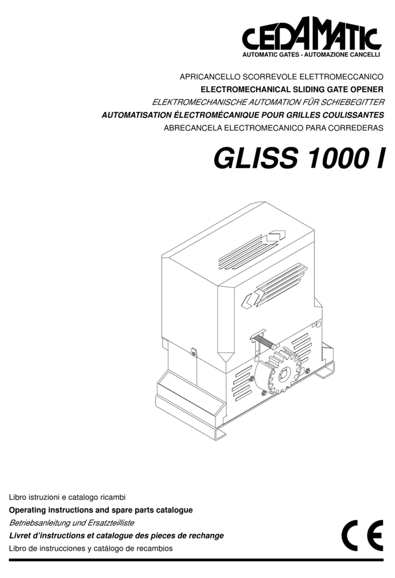
cedamatic GLISS 1000 I User manual

GLISS 1000 I
CENTRALINAA MICROPROCESSORE PER
CONTROL UNIT WITH MICROCONTROLLER FOR
MIKROCONTROLLER-STEUERUNG FÜR
CENTRALE A MICROCONTRÔLEUR POUR
CENTRALITAA MICROPROCESADOR POR
Libro istruzioni
Operating instructions
Betriebsanleitung
Livret d’instructions
Libro de instrucciones
AUTOMATIC GATES - AUTOMAZIONE CANCELLI

2
Dichiarazione CE di conformità Déclaration CE de conformité
EC declaration of confirmity Declaracion CE de conformidad
EG-Konformitatserklarung
Con la presente dichiariamo che il nostro prodotto
We hereby declare that our product
Hiermit erklaren wir, dass unser Produkt
Nous déclarons par la présente que notre produit
Por la presente declaramos que nuestro producto
GLISS 1000 I
è conforme alle seguenti disposizioni pertinenti:
complies with the following relevant provisions:
folgenden einschlagigen Bestimmungen entspricht:
correspond aux dispositions pertinentes suivantes:
satisface las disposiciones pertinentes siguientes:
Direttiva sulla compatibilità elettromagnetica (89/336/
CCE, 93/68/CEE)
EMC guidelines (89/336/EEC, 93/68/EEC)
EMV-Richtlinie (89/336/EWG, 93/68/EWG)
Directive EMV (89/336/CCE, 93/68/CEE) (Compatibilité
électromagnétique)
Reglamento de compatibilidad electromagnética (89/336/
MCE, 93/68/MCE)
Norme armonizzate applicate in particolare:
Applied harmonized standards, in particular:
Angewendete harmonisierte Normen, insbesondere:
Normes harmonisée utilisées, notamment:
Normas armonizadas utilzadas particularmente:
EN 55022, EN 61000-3-2, EN 61000-3-3, EN 50082-1
Direttiva sulla bassa tensione (73/23/CEE, 93/68/CEE)
Low voltage guidelines (73/23/EEC, 93/68/EEC)
Tiefe Spannung Richtlinie (73/23/EWG, 93/68/EWG)
Directive bas voltage (73/23/CEE, 93/68/CEE)
Reglamento de bajo Voltaje (73/23/MCE, 93/68/MCE)
Norme armonizzate applicate in particolare:
Applied harmonized standards, in particular:
Angewendete harmonisierte Normen, insbesondere:
Normes harmonisée utilisées, notamment:
Normas armonizadas utilzadas particularmente:
EN 60204-1, EN 60335-1

3
INPUT LAMP.
230VAC
Chiude
Apre
P.P.
Stop
FTC
FCA
FCC
+V
ASC
8k2
8k2
ASA
N
Chiude Apre COM.
F
230VAC 50Hz M
Sensore giri
SCA
24VAC
OUT
ANT Z8
C4
R29
D18
R8
C18
C19 R32 R40
U6
R4
Z9
C21
C15
D26
D25
D9
D8
D7
D6
D5
D4
D3
R57
C20
C16
U3
L2
R61
K4
J3 RTX
D33
Z1
Z2
Z3
Z4
Z5
Z6
Z7
U1
U7
D31
D30
C1
D23
D22
R39
R49
R48
R56
R60
R33
R30
R35
D24
R54
C22
R28
R47
R50
R53
D27
R67
R52
R51
R63
1
33
32
31
30
29
28
FUSE
IN.
230V
C24
R1
R2
R3
L3
AP.
CH.
P.P.
STOP
FTC
FCA
FCC
ASC
ASA
J1
R27
C2
R59
C3
R58
D32
R31
R12 C13
R13
C12
R14
C11
R15
C10
R17
C9
R18
C8
R16
C7
R19
R26
R11
R25
R10
R24
R9
R23
R7
R22
R6
R21
R20
D2
R36
D10
D11
D12
D13
D14
D15
D16
J2
VDR3
SW1
C6
C5 0
F2 2A
FUSE
FUSE
F1 6.3A
F3 2A
F1
D1
VDR1 C14
C17
+
F2 2A
R46 R44
Q9 D17
D19 D21 D20
R45
R43
R5
K2 K1 K3
D34Power
234567 891011121314151617181920212223
24
SW2 Select
PGM
Q4
RX
2 CH.
25
26
27

4
Centralina a microprocessore per GLISS 1000 I
La centrale a microprocessore GLISS 1000 I può essere usata per comandare motori di potenza non superiore
a 750W.
Consigli per l’installazione
a) L’installazione elettrica e la logica di funzionamento devono essere in accordo con le normative vigenti.
b) È consigliabile tenere i cavi di potenza (motore, alimentazione) distinti da quelli di comando (pulsanti,
fotocellule, radio). Per evitare interferenze è preferibile prevedere ed utilizzare due guaine separate.
c) Ricontrollare velocemente tutti i collegamenti fatti prima di dare tensione.
d) Controllare che le impostazioni dei Dip-Switch siano quelle volute.
e) Dando tensione il led “POWER” si deve illuminare, in caso contrario controllare l’integrità dei fusibili e la
presenza di 230Vac, 50Hz tra i morsetti 1 e 2 (INPUT 230VAC - rispettare fase/neutro).
f) Tutti gli ingressi normalmente chiusi che non si desidera utilizzare devono essere cortocircuitati con il rispet-
tivo DSW posto vicino al connettore di collegamento degli ingressi stessi.
g) Nel caso che il senso di rotazione del motore sia invertito, basta invertire i fili “APRE” - “CHIUDE” del motore
stesso e i fili dei finecorsa “FCA” - “FCC”.
Funzione Ingressi/Uscite
(1,2) Ingresso 230Vac= Alimentazione centrale 230Vac, 50Hz (Fase: morsetto 2, Neutro: morsetto 1).
(3,4,5) Uscita Motore= Rispettivamente Chiude (3), Apre (4) e Comune (5).
(6,7) LAMP= Al lampeggiante a 230Vac
(8) CHIUDE= Contatto N.O.
(9) APRE= Contatto N.O. (commutabile a ingresso “Pedonale”)
(10) P.P.= Ingresso PASSO/PASSO. Collegato in parallelo all’uscita del radiocomando. Contatto N.O.
(11) STOP= Contatto N.C.
(12) FTC= Da collegare al contatto di uscita della fotocellula. Contatto N.C.
(13) FCA= Ingresso finecorsa di apertura. Contatto N.C.
(14) FCC= Ingresso finecorsa di chiusura. Contatto N.C.
(15,16) +V= Uscita comune per tutti gli ingressi
(17) ASC= Ingresso per costa; provoca l’inversione di marcia per 1 secondo se il motore è in fase di chiu-
sura*.
(18) Ingresso comune delle coste= Ingresso comune delle coste; le coste NON DEVONO ESSERE COL-
LEGATE AL COMUNE DEI PULSANTI
(19) ASA= Ingresso per costa; provoca l’inversione di marcia per 1 secondo se il motore è in fase di aper-
tura*
(20,21) SCA= Contatto “Spia cancello aperto”, lampada 24Vac
(22,23) OUT 24VAC= Uscita alimentazione ausiliaria 24Vac (1A max.)
(24,25) Uscita 2°canale= Contatto N.O. comandato dal secondo canale del radiocomando
(26,27) Ingresso antenna= Collegamento antenna per scheda ricevente del radiocomando.
Schermo= morsetto 25
(28,29) Ingresso 24VAC= Collegamento al secondario del trasformatore 24V
(30,31) Condensatore= Collegamento al condensatore
(32,33) Uscita 230VAC= Collegamento al primario del trasformatore 24V
RTX= Connettore scheda ricevente del radiocomando.
*Gli ingressi delle coste sono a resistenza calibrata.
Se si usa una costa resistiva, i rispettivi ponticelli (J2 per ASC e J1 per ASA) vanno chiusi, mentre se si usa
una costa meccanica i ponticelli vanno lasciati aperti.
Nel caso in cui si decida di non installare le coste, lasciare il rispettivo ponticello aperto e mettere in ON il
DSW di cortocircuito (il n°1 per ASA ed il n°2 per ASC).
N.B.: Per la costa ci sono due ingressi dedicati, NON COLLEGARE MAI LACOSTAAL MORSETTO COMU-
NE.
ATTENZIONE: Non toccare le parti metalliche quando la centrale è sotto tensione.
Funzione Dip-Switch
DSW1 Modo di funzionamento per l’ingresso “P.P.” e del telecomando.
Off: Sequenza Apre/Stop/Chiude
On: Sequenza Apre/Chiude/Apre
DSW2 Funzione “Uomo Presente”. L’automazione esegue le manovre di apertura e chiusura per il tempo in cui
rimangono premuti i pulsanti Apre e Chiude rispettivamente.
Off: Funzione Uomo Presente disabilitata
On: Funzione Uomo Presente abilitata. In questo caso non è possibile utilizzare Apre come pedonale.
DSW3 Funzione “Condominiale”: l’ingresso “P.P.” non ferma il motore durante la fase di apertura. Ad apertura

5
completata, l’ingresso “P.P.” è abilitato per la chiusura del cancello.
Off: Funzione condominiale disabilitata
On: Funzione condominiale abilitata
DSW4 Funzione “Prelampeggio”: la luce lampeggiante viene attivata 3 secondi prima dell’inizio di ogni mano-
vra.
Off: Prelampeggio disabilitato
On: Prelampeggio abilitato
DSW5 Intervento fotocellula durante la fase di apertura: se il fascio della fotocellula viene interrotto, il motore
si ferma. La manovra riprende 1 secondo dopo che la fotocellula viene disimpegnata.
Off: Nessun intervento
On: Stop temporaneo
DSW6 Funzione “Pedonale”: l’ingresso “Apre” comanda l’apertura parziale (regolabile da 1,5 a 10 metri circa).
Off: Funzionamento come “PulsanteApre”
On: Funzionamento come “Pulsante Pedonale”
DSW7 Spunto alla partenza
Off: Spunto alla partenza disabilitato
On: Spunto alla partenza abilitato
DSW8 Chiusura automatica.
Off: Chiusura automatica disabilitata
On: Chiusura automatica abilitata
Le selezioni impostate con i Dip-Switch vengono acquisite nella fase di Stop; se si opera una variazione alla
configurazione dei Dip-Switch, il funzionamento della centrale si modificherà dopo la fermata successiva.
Funzione Dip-Switch ”Bypass”
I Dip-Switch “Bypass” consentono di cortocircuitare gli ingressi normalmente chiusi che non si desidera utilizza-
re.
DSW1 Ingresso ASA
Off: Ingresso abilitato
On: Ingresso disabilitato (lasciare aperto il ponticello).
DSW2 Ingresso ASC
Off: Ingresso abilitato
On: Ingresso disabilitato (lasciare aperto il ponticello).
DSW3 Ingresso FCC
Off: Ingresso abilitato
On: Ingresso disabilitato.
DSW4 Ingresso FCA
Off: Ingresso abilitato
On: Ingresso disabilitato.
DSW5 Ingresso FTC
Off: Ingresso abilitato
On: Ingresso disabilitato.
DSW6 Ingresso Stop
Off: Ingresso abilitato
On: Ingresso disabilitato.
Funzioni programmabili
La centrale GLISS 1000 I è dotata del connettore per la comunicazione con il display di programmazione; se
non si desidera utilizzare il display è possibile programmare la centrale nel modo seguente.
Le funzioni per le quali è possibile scegliere tra un intervallo di valori vengono impostate utilizzando il pulsante
di programmazione (PGM) assieme ai Dip-Switch. I valori predefiniti sono indicati con “(def.)”.
Per memorizzare le funzioni programmabili, posizionare i Dip-Switch come indicato in tabella, quindi premere il
pulsante PGM per almeno 2 secondi. Il led “PGM”, normalmente lampeggiante, rimane acceso a luce fissa;
quando il led si spegne la programmazione è stata eseguita, si può rilasciare il pulsante, il led ricomincia a
lampeggiare. Una volta terminata la programmazione, riportare i Dip-Switch nelle posizioni normali.
Questa centrale esegue automaticamente il test di integrità del circuito di potenza. Qualora dovesse rilevare un
malfunzionamento essa si blocca e segnala l’anomalia con due lampeggi ravvicinati del led PGM.
L’intervento della protezione termica è visto come un’anomalia del circuito di potenza, una volta che la protezio-
ne termica ripristina il collegamento, la centrale riparte automaticamente.
Se la centrale continua a segnalare il guasto anche quando il motore si è raffreddato, provare a togliere mo-
mentaneamente l’alimentazione.

6
Funzione Opzioni
Tempo di lavoro funzione "Pedonale".
Dip-switch 1÷4= On/Off/On/Off
ON
1234
Dsw5 Dsw6 Dsw7 Dsw8 Secondi
Off Off Off Off 5
On Off Off Off 10 (def.)
Off On Off Off 15
On On Off Off 20
Off Off On Off 25
On Off On Off 30
Off On On Off 35
On On On Off 40
Tempo di attesa per la chiusura automatica.
Dip-switch 1÷4= On/On/Off/Off
Il tempo d’attesa èazzerato, se il contatto dell’ingresso
FTC viene aperto o il contatto dell’ingresso Apre resta
chiuso.
ON
1234
Dsw5 Dsw6 Dsw7 Dsw8 Secondi
Off Off Off Off 5
On Off Off Off 10
Off On Off Off 15
On On Off Off 20
Off Off On Off 30
On Off On Off 40
Off On On Off 50
On On On Off 60 (def.)
Off Off Off On 80
On Off Off On 100
Off On Off On 120
On On Off On 140
Off Off On On 160
On Off On On 180
Off On On On 200
On On On On 220
Potenza di funzionamento.
Dip-switch 1÷4= Off/On/On/Off
ON
1234
Dsw5 Dsw6 Dsw7 Dsw8 Percent.
Off Off Off Off
Pot. Min.
On Off Off Off
Off On Off Off
On On Off Off
Off Off On Off
On Off On Off
Off On On Off
On On On Off (def.)
Off Off Off On
On Off Off On
Off On Off On
On On Off On
Off Off On On
On Off On On
Off On On On
On On On On
Pot. Max.

7
Funzione Opzioni
Funzioni programmabili.
Dip-switch 1÷4= Off/On/Off/Off
DSW5
On= In caso di guasto delle protezioni parte
automaticamente in Uomo Presente dopo 2 sec.
di pressione del pulsante.
Off= In caso di guasto delle protezioni non parte
neanche dopo una pressione prolungata del
pulsante (def.).
DSW6
On= Rallentamento inserito. Circa 15 secondi
prima della fine di TL, la centrale esegue un
rallentamento (def.).
Off= Rallentamento disinserito.
DSW7= Off
DSW8= Off
ON
1234
Il Tempo di lavoro viene regolato con il seguente menù, dopo la partenza del motore dal finecorsa, sette
secondi prima che sia trascorso il tempo impostato, la centrale inizia il rallentamento (se questo èselezionato).
Se il tempo di lavoro viene modificato prima di poter vedere il funzionamento corretto della centrale bisogna
fargli fare una manovra completa (cioècon arrivo su un finecorsa e ripartenza dallo stesso).
L’intervento delle coste di protezione disinserisce il rallentamento fino alla prima manovra completa successiva
(cioècon arrivo su un finecorsa e ripartenza dallo stesso).
Tempo di lavoro.
Dip-switch 1÷3= Off/Off/On
ON
123
Dsw5 Dsw6 Dsw7 Dsw8
Secondi
Off
Off
On
On
Off
Off
On
On
Off
Off
On
On
Off
Off
On
On
Off
Off
On
On
Off
Off
On
On
Off
Off
On
On
Off
Off
On
On
Off
Off
Off
Off
On
On
On
On
Off
Off
Off
Off
On
On
On
On
Off
Off
Off
Off
On
On
On
On
Off
Off
Off
Off
On
On
On
On
Off
Off
Off
Off
Off
Off
Off
Off
On
On
On
On
On
On
On
On
Off
Off
Off
Off
Off
Off
Off
Off
On
On
On
On
On
On
On
On
Off
Off
Off
Off
Off
Off
Off
Off
Off
Off
Off
Off
Off
Off
Off
Off
On
On
On
On
On
On
On
On
On
On
On
On
On
On
On
On
15
18
21
24
27
30
33
36
39
42
45
48
51
54
57 (def.)
60
63
66
69
72
75
78
81
84
87
90
93
96
99
102
105
108
Dsw4
Off
On
Off
On
Off
On
Off
On
Off
On
Off
On
Off
On
Off
On
Off
On
Off
On
Off
On
Off
On
Off
On
Off
On
Off
On
Off
On

8
GLISS 1000 I control unit with microcontroller
The control unit with microprocessor GLISS 1000 I can be used to control motors featuring a power not
exceeding 750W.
Installation instructions.
a) Wire connections and operating logic should comply with regulations in force.
b) It is recommended to keep the power cables (motor, power supply) detached from the control ones
(push-buttons, photocells, radio). To avert any interference, it is advised to use two distinct sheaths.
c) Before powering the unit, rapidly check all connections.
d) Check the correct setting of the Dip-Switches.
e) When the unit is powered, the LED “POWER”must light on. In the negative, check the good condition
of fuses and the presence of 230Vac, 50Hz between terminals 1 and 2 (INPUT 230VAC - follow phase/
neutral).
f) All normally closed inputs, which are not in use, should be short-circuited with the relevant Dip-
Switch located near the connection terminal of the inputs.
g) If the rotation direction of the motor is inverted, it is sufficient to invert the wires “APRE”- “CHIUDE”
(OPEN - CLOSE) of the motor as well as the limit switches wires “FCA”- “FCC”.
Input/Output functions
(1,2) Input, 230VAC= Power supply of the control unit 230Vac, 50Hz (Phase: terminal 2, Neutral: ter-
minal 1).
(3,4,5) Output, Motor= Respectively, Close (3), Open (4) and Common (5).
(6,7) LAMP= To the flashing light at 230Vac
(8) CHIUDE= Normally Open (N.O.) contact
(9) APRE= N.O. contact (it can be switched to “Pedestrian”input)
(10) P.P.= Input, STEP-BY-STEP. Connected in parallel to the remote control. N.O. contact.
(11) STOP= Normally closed (N.C.) contact
(12) FTC= To be connected to the output terminal of the photocell. N.C. contact
(13) FCA= Input, opening limit switch. N.C. contact
(14) FCC= Input, closing limit switch. N.C. contact
(15,16) +V= Output, common for all inputs
(17) ASC= Input, safety edge. Its activation causes the movement reversion for 1 second if the mo-
tor is in the closing phase*
(18) Input, common to the safety edges = Input, common of safety edges. The safety edges MUST
NOT BE CONNECTED TO THE COMMON OF THE PUSH-BUTTONS
(19) ASA= Input, safety edge. Its activation causes the movement reversion for 1 second if the mo-
tor is in the opening phase*
(20,21) SCA= “Open gate LED”contact, 24Vac bulb
(22,23) OUT 24VAC= Output, auxiliary power supply, 24Vac (1A max.)
(24,25) Output, 2nd channel= N.O. contact, controlled by the second channel of the remote control
(26,27) Input, antenna= Antenna connection for the receiving card of the remote control.
Display= terminal 25
(28,29) Input, 24VAC= Connection to the secondary of the transformer, 24V
(30,31) Capacitor= Connection to the capacitor
(32,33) Output, 230VAC= Connection to the primary of the transformer, 24V
RTX= Connector to the receiving card of the remote control.
* The inputs of the safety edges are at calibrated resistance. If a resistive safety edge is used, the
relevant jumpers (J2 for ASC and J1 for ASA) should be closed. Conversely, if a mechanical edge is
used the jumpers should be left open. In the event the safety edges are not mounted, leave the corre-
sponding jumper open and move the short-circuit Dip-Switch to ON (No. 1 for ASA and no. 2 for ASC).
N.B.: for the safety edge, two inputs are provided, NEVER CONNECT THE SAFETY EDGE TO THE
COMMON TERMINAL.
CAUTION: When the control unit is powered, do not touch any metallic parts.
DSW1 Operating mode of the “P.P. button”and of the remote control.
Off: Open/Stop/Close sequence
On: Open/Close/Open sequence
DSW2 “Service man”function. The automatic system carries out the opening and closing operations
as long as the Open and Close push-buttons, respectively are kept pressed.
Off: Service Man function disabled
On: Service man function enabled. In this case the Open push-button cannot be used as control
for pedestrian use.

9
DSW3 “Multiple-flat”function: the “P.P.”(STEP-BY-STEP) input does not cause the motor stopping in
the opening phase. At end of opening, the “P.P.”input is enabled for the gate closure.
Off: Multiple-flat function is disabled
On: Multiple-flat function is enabled
DSW4 “Forewarning”function: the flashing light switches on 3 seconds before the beginning of every
movement.
Off: Forewarning flashing light is disabled
On: Forewarning flashing light is enabled
DSW5 Photocell activation during the opening phase. If the photocell beam is obscured, the motor
stops. The movement starts after 1 second from the photocell reset.
Off: No activation
On: Temporary stop
DSW6 “Pedestrian”function: the “Open”input controls the temporary opening (adjustable from about
1.5 to 10 metres).
Off: Operation as “Open Push-button”
On: Operation as “Pedestrian push-button”
DSW7 Pick-up at start
Off: Pick-up at start disabled
On: Pick-up at start enabled
DSW8 Automatic closure.
Off: Automatic closure disabled
On: Automatic closure enabled
The selections which are preset with the Dip-Switches are memorized in the Stop phase. If a variation to
the configuration of the Dip-Switches is carried out, the control unit operation is modified after the
following stop.
Dip-Switch “Bypass”Function
The Dip-Switches “Bypass”allow to short-circuit the normally closed inputs that are not in use.
DSW1 Input ASA
Off= Enabled input
On= Disabled input (leave the gate open).
DSW2 Input ASC
Off= Enabled input
On= Disabled input (leave the gate open).
DSW3 Input FCC
Off= Enabled input
On= Disabled input.
DSW4 Input FCA
Off= Enabled input
On= Disabled input.
DSW5 Input FTC
Off= Enabled input
On= Disabled input.
DSW6 Input STOP
Off= Enabled input
On= Disabled input.
Programmable functions
The GLISS 1000 I control unit is equipped with connector to communicate with the programming display. If
the display is not used, the control unit can be programmed as follows:
The functions for which it is possible to choose between a range of values can be preset by using the
programming push-button (PGM) together with the Dip-switches. The fixed values are indicated with “(def.)”.
To store the programmable functions in memory, move the Dip-switches as shown in the table, then press
the push-button PGM for at least 2 seconds. The light of the “PGM”LED, which normally flashes, will be
steady. When the LED switches off, then the programming has been successfully carried out. At this point,
the push-button can be released and the LED start flashing.
At completion of the programming procedure, move the Dip-switches to the normal positions.
This control unit performs the power circuit integrity test automatically. Should a fault be detected, the unit
stops and indicates the fault through two blinks of the PGM led in rapid succession.
The triggering of the thermal switch is considered a fault in the power circuit, and once the thermal protec-
tion is reset, the control unit restarts automatically. If the control unit keeps on indicating a faulty operation,
even when the motor has cooled down, try to momentarily switch power off.

10
Function Options
Operating time of the "Pedestrian" function.
Dip-switch 1÷4= On/Off/On/Off
ON
1234
Dsw5 Dsw6 Dsw7 Dsw8 Seconds
Off Off Off Off 5
On Off Off Off 10 (def.)
Off On Off Off 15
On On Off Off 20
Off Off On Off 25
On Off On Off 30
Off On On Off 35
On On On Off 40
Dwell time for the automatic closure.
Dip-switch 1÷4= On/On/Off/Off
The dwell time is reset when the input FTC contact is opened
or the Open input contact stays open.
ON
1234
Dsw5 Dsw6 Dsw7 Dsw8 Seconds
Off Off Off Off 5
On Off Off Off 10
Off On Off Off 15
On On Off Off 20
Off Off On Off 30
On Off On Off 40
Off On On Off 50
On On On Off 60 (def.)
Off Off Off On 80
On Off Off On 100
Off On Off On 120
On On Off On 140
Off Off On On 160
On Off On On 180
Off On On On 200
On On On On 220
Operating power.
Dip-switch 1÷4= Off/On/On/Off
ON
1234
Dsw5 Dsw6 Dsw7 Dsw8 Percent.
Off Off Off Off
Min. Pow.
On Off Off Off
Off On Off Off
On On Off Off
Off Off On Off
On Off On Off
Off On On Off
On On On Off (def.)
Off Off Off On
On Off Off On
Off On Off On
On On Off On
Off Off On On
On Off On On
Off On On On
On On On On
Max Pow.

11
Function Options
Programmable functions.
Dip-switch 1÷4= Off/On/Off/Off
DSW5
On= In case of failure of the protection devices, the
system switches automatically to "Service Man"
operating mode after pressing the push-button for
2 seconds.
Off= In case of failure of the protection devices, the
system cannot be activated even after pressing the
push-button (def.).
DSW6
On= Braking enebled. About 15 seconds before the
end of the operating time, the control unit sends a
braking control signal (def.).
Off= Braking disabled.
DSW7= Off
DSW8= Off
ON
1234
The work time is regulated with the following menu, after the motor has been started from the limit switch; 7 seconds before
the set time has elapsed the control unit starts slowing down (if this has been selected). If the work time is modified before
you have been able to see the correct operation of the control unit, you must make it perform a complete manoeuvre (that
is with arrival on a limit switch and restarting from the same point). The intervention of the protection edges deactivates
slowing down until the first subsequent complete manoeuvre (that is with arrival on a limit switch and restarting from the
same point).
Operating time.
Dip-switch 1÷3= Off/Off/On
ON
123
Dsw5 Dsw6 Dsw7 Dsw8
Seconds
Off
Off
On
On
Off
Off
On
On
Off
Off
On
On
Off
Off
On
On
Off
Off
On
On
Off
Off
On
On
Off
Off
On
On
Off
Off
On
On
Off
Off
Off
Off
On
On
On
On
Off
Off
Off
Off
On
On
On
On
Off
Off
Off
Off
On
On
On
On
Off
Off
Off
Off
On
On
On
On
Off
Off
Off
Off
Off
Off
Off
Off
On
On
On
On
On
On
On
On
Off
Off
Off
Off
Off
Off
Off
Off
On
On
On
On
On
On
On
On
Off
Off
Off
Off
Off
Off
Off
Off
Off
Off
Off
Off
Off
Off
Off
Off
On
On
On
On
On
On
On
On
On
On
On
On
On
On
On
On
15
18
21
24
27
30
33
36
39
42
45
48
51
54
57 (def.)
60
63
66
69
72
75
78
81
84
87
90
93
96
99
102
105
108
Dsw4
Off
On
Off
On
Off
On
Off
On
Off
On
Off
On
Off
On
Off
On
Off
On
Off
On
Off
On
Off
On
Off
On
Off
On
Off
On
Off
On

12
Zentrale mit Mikroprozessor GLISS 1000 I
Die Zentrale mit Mikroprozessor
GLISS 1000 I
kann verwendet werden, um Motoren von einer Leistung bis maximal
750W zu steuern.
Empfehlungen für den Einbau
a) Die elektrische Installation und die Betriebslogik müssen den geltenden Normen entsprechen.
b) Wir empfehlen die Leistungskabel (Motor, Speisung) von den Kabeln der Steuerungen (Tasten, Fotozellen, Ra-
dio) getrennt zu halten. Um Störungen zu vermeiden, sollten zwei getrennte Kabelmäntel verwendet werden.
c) Alle Anschlüsse nochmals kontrollieren, bevor die Zentrale eingeschaltet wird.
d) Kontrollieren, ob die Dip-Schalter in die gewünschten Positionen geschaltet wurden.
e) Beim Einschalten muß die Leuchte “POWER” aufleuchten; sollte dies nicht der Fall sein, die Sicherungen auf
Integrität kontrollieren und sicherstellen, dass zwischen den Klemmen 1 und 2 die Stromversorgung 230Vac,
50Hz beträgt (INPUT 230VAC - Fase/Nulleiter einhalten).
f) Alle Eingänge im Ruhekontakt, die nicht verwendet werden sollen, müssen mit dem entsprechenden DSW in der
Nähe des Verbinders derselben Eingänge kurzgeschlossen werden.
g) Falls die Drehrichtung des Motors falsch sein sollte, die Leiter “ÖFFNEN” - “SCHLIESSEN” des Motors und die
Leiter der Endschalter “FCA” - “FCC” umkehren.
Funktion Eingaben/Ausgaben
(1,2) Eingang 230Vac= Speisung der Zentrale 230Vac, 50Hz (Fase: Klemme 2, Nulleiter: Klemme 1).
(3,4,5) Ausgang Motor= bzw. schließen (3), öffnen (4) und Mittelleiter (5).
(6,7) LAMP= zur Blinkleuchte zu 230Vac
(8) CHIUDE (schließen)= Kontakt N.O.
(9) APRE (öffnen)= Kontakt N.O. (kann als Eingang für “Fußgänger” verwendet werden)
(10) P.P.= Eingang SCHRITT/SCHRITT. Parallel mit dem Ausgang der Fernbedienung geschaltet. Kontakt N.O.
(11) STOP= Kontakt N.C.
(12) FTC= Mit dem Ausgangskontakt der Fotozelle zu verbinden. Kontakt N.C.
(13) FCA= Eingang Endschalter Öffnen. Kontakt N.C.
(14) FCC= Eingang Endaschalter Schließen. Kontakt N.C.
(15,16) +V= Gemeinsamer Ausgang für alle Eingänge
(17) ASC= Eingang für Flanke; bewirkt das Umschalten des Ganges für 1 Sekunde, wenn der Motor auf Schlie-
ßen geschaltet ist.*
(18) Gemeinsamer Eingang der Flanken = Gemeinsamer Eingang der Flanken; die Flanken
DÜRFEN NICHT
AN DEN MITTELLEITER DER TASTEN GESCHLOSSEN WERDEN
(19) ASA= Eingang für Flanke; bewirkt das Umschalten des Ganges für 1 Sekunde, wenn der Motor auf Öffnen
geschaltet ist.*
(20,21) SCA= Kontakt “Leuchte für offenes Tor”, Birne 24Vac
(22,23) OUT 24VAC= Ausgang Hilfsspeisung 24Vac (1A max.)
(24,25) Ausgang 2. Kanal= Kontakt N.O. durch den zweiten Kanal der Fernbedienung gesteuert
(26,27) Antenneneingang= Antennenanschluss für Empfängerkarte der Fernsteuerung.
Bildschirm= Klemme 25
(28,29) Eingang 24VAC= Anschluss zur Sekundärwicklung des Trafos 24V
(30,31) Kondensator = Anschluss zum Kondensator
(32,33) Ausgang 230VAC= Anschluss zur Primärwicklung des Trafos 24V
RTX
= Verbinder Empfängerkarte der Fernbedienung.
* Die Eingänge der Flanken haben einen kalibrierten Widerstand.
Wird eine widerstandsfähige Flanke verwendet, müssen die entsprechenden Brücken (J2 für ASC und J1 fürASA)
geschlossen werden; wenn aber mechanische Flanken verwendet werden, müssen die Brücken offen bleiben.
Falls keine Flanken vorgesehen sind, die entsprechende Brücke offen lassen und DSW für den Kurzschluss auf
ON schalten (Nr. 1 für ASAund Nr. 2 fürASC).
N.B.: Für die Flanke sind zwei Spezialeingänge vorgesehen,
DIE FLANKE NIEMALS AN DEN MITTELLEITER
SCHLIESSEN
.
ACHTUNG
: Metallteile nicht berühren, wenn die Zentrale eingeschaltet ist.
Funktion der Dip-Drucktasten
DSW1
Betriebsart des Eingangs “P.P.” und der Fernbedienung.
Off: Reihenfolge Öffnen/Stop/Schließen
On: Reihenfolge Öffnen/Schließen/Öffnen
DSW2
Funktion “Person vorhanden”. Die Automatik öffnet und schließt solange die Tasten Öffnen bzw. Schließen
gedrückt bleiben.
Off: Funktion Person vorhanden deaktiviert
On: Funktion Person vorhanden aktiviert. In diesem Fall kann die Funktion Öffnen nicht als Fußgänger-

13
funktion verwendet werden.
DSW3
Funktion “Wohngemeinschaft”: der Eingang “P.P.” hält den Motor beim Öffnen nicht an. Wenn der Öffnungs-
vorgang beendet ist, wird der Eingang “P.P.” freigegeben, um das Tor zu schließen.
Off: Wohngemeinschaftsfunktion deaktiviert
On: Wohngemeinschaftsfunktion aktiviert
DSW4
Funktion “Vorblinken”: die Blinkleuchte wird 3 Sekunden vor jeder Bewegung aktiviert.
Off: Vorblinken deaktiviert
On: Vorblinken aktiviert
DSW5
Fotozelle schaltet beim Öffnen ein: wenn der Strahl der Fotozelle unterbrochen wird, hält der Motor an. 1
Sekunde nachdem die Fotozelle wieder frei ist, wird die Bewegung wieder aufgenommen.
Off: Keine Reaktion
On: Vorübergehend anhalten
DSW6
Funktion “Fußgänger”: der Eingang “Öffnen” steuert eine Teilöffnung (von 1,5 bis 10 Meter einstellbar).
Off: Funktioniert als “Öffnungstaste ”
On: Funktioniert als “Fußgängertaste ”
DSW7
Anlassstoß
Off: Anlassstoß deaktiviert
On: Anlassstoß aktiviert
DSW8
Automatisch schließen
Off: Automatisch schließen deaktiviert
On: Automatisch schließen aktiviert
DieüberdieDip-SchaltervorgenommenenEinstellungenwerden in der Stop-Fase übernommen; wird die Konfigura-
tion der Dip-Schalter geändert, stellt sich die Zentrale nach dem darauffolgenden Halt darauf ein.
Funktion Dip-Schalter ”Bypass”
Die "Bypass“Dip-Schalter ermöglichen es, die Eingänge mit Ruhekontakt, die nicht verwendet werden sollen,
kurzzuschließen.
DSW1
Eingang ASA
Off= Eingang frei
On= Eingang gesperrt (Brücke offen lassen).
DSW2
Eingang ASC
Off= Eingang frei
On= Eingang gesperrt (Brücke offen lassen).
DSW3
Eingang FCC
Off= Eingang frei
On= Eingang gesperrt.
DSW4
Eingang FCA
Off= Eingang frei
On= Eingang gesperrt.
DSW5
Eingang FTC
Off= Eingang frei
On= Eingang gesperrt.
DSW6
Eingang STOP
Off= Eingang frei
On= Eingang gesperrt.
Programmierbare Funktionen
Die Zentrale
GLISS 1000 I
ist mit einem Verbinder zur Kommunikation mit dem Programmierungsdisplay ausgestat-
tet; soll zur Programmierung das Display nicht verwendet werden, kann die Zentrale folgendermaßen programmiert
werden.
DieFunktionen für welche ein Wertabstandgewählt werdenkann, werden über die Programmiertaste (
PGM
)und die
Dip-Schalter programmiert. Die voreingegebenen Werte sind durch “(def.)” gekennzeichnet.
Um die programmierbaren Funktionen zu speichern, die Dip-Schalter laut Angaben der Tabelle positionieren, dann
die Taste PGM mindestens 2 Sekunden lang drücken. Die normalerweise blinkende Leuchte “PGM” leuchtet fest;
wenn sie erlischt ist die Programmierung gespeichert und die Taste kann losgelassen werden; die Leuchte blinkt
wieder. Wenn die Programmierung beendet ist, die Dip-Schalter wieder in ihre Ausgangspositionen bringen.
Diese Zentrale testet automatisch die Funktionstüchtigkeit des Leistungskreislaufes. Falls eine Störung ermit-
telt wird, blockiert sie sich und meldet die Störung durch zweimaliges kurz aufeinander folgendes Blinken der
Led
PGM
.
Das Einschalten des Schutzschalters bedeutet, dass der Leistungskreislauf gestört ist. Wenn der Schutzschalter
den Anschluss wieder herstellt, schaltet die Zentrale automatisch wieder ein. Falls die Zentrale auch bei abge-
kühltem Motor weiterhin die Störung melden sollte, vorübergehend die Speisung abtrennen.

14
Funktion Optionen
Arbeitszeit Funktion “Fußgänger”.
Dip-switch 1÷4= On/Off/On/Off
ON
1234
Dsw5 Dsw6 Dsw7 Dsw8
Sekunden
Off Off Off Off 5
On Off Off Off 10 (def.)
Off On Off Off 15
On On Off Off 20
Off Off On Off 25
On Off On Off 30
Off On On Off 35
On On On Off 40
Wartezeit für den automatischen Schließvorgang.
Dip-switch 1÷4= On/On/Off/Off
Die Wartezeit wird auf Null gestellt, wenn der Kontakt des
Einganges FTC geöffnet wird oder der Kontakt des
Eingangs Öffnen geschlossen bleibt.
ON
1234
Dsw5 Dsw6 Dsw7 Dsw8
Sekunden
Off Off Off Off 5
On Off Off Off 10
Off On Off Off 15
On On Off Off 20
Off Off On Off 30
On Off On Off 40
Off On On Off 50
On On On Off 60 (def.)
Off Off Off On 80
On Off Off On 100
Off On Off On 120
On On Off On 140
Off Off On On 160
On Off On On 180
Off On On On 200
On On On On 220
Betriebsleistung.
Dip-switch 1÷4= Off/On/On/Off
ON
1234
Dsw5 Dsw6 Dsw7 Dsw8
Prozents.
Off Off Off Off
Min. Leist.
On Off Off Off
Off On Off Off
On On Off Off
Off Off On Off
On Off On Off
Off On On Off
On On On Off (def.)
Off Off Off On
On Off Off On
Off On Off On
On On Off On
Off Off On On
On Off On On
Off On On On
On On On On
Max. Leist.

15
Funktion Optionen
Programmierbare Funktionen.
Dip-switch 1÷4= Off/On/Off/Off
DSW5
On= Bei defekten Schutzvorrichtungen schaltet
es automatisch 2 Sekunden nachdem die Taste
gedrückt wurde, auf Person vorhanden.
Off= Bei defekten Schutzvorrichtungen schaltet
es überhaupt nicht ein, auch nicht wenn die
Taste längere Zeit gedrückt bleibt (def.).
DSW6
On= Geschwindigkeitsabnahme ein. Circa 15
Sekunden vor dem Ende des TL nimmt die Zen-
trale eine Geschwindigkeitsabnahme vor (def.).
Off= Geschwindigkeitsabnahme aus.
DSW7= Off
DSW8= Off
ON
1234
Die Betriebszeit wird mit dem folgenden Menüreguliert, nach dem Anlaufen des Motors vom Endschalter, löst das
Steuergerät sieben Sekunden vor Ablauf der eingestellten Zeit die Verlangsamung aus (sofern diese selektiert ist).
Wenn die Betriebszeit verändert wird, bevor die korrekte Funktion des Steuergerätes erprobt wurde, muss ein kom-
plettes Manöver ausgeführt werden (das heißt mit Eintreffen an einem Endschalter und erneutesAnlaufen ab diesem).
Das Auslösen der Sicherheitsleisten deaktiviert die Verlangsamung bis zum folgenden kompletten Manöver (das heißt
mit Eintreffen an eine Endschalter und erneutesAnlaufen ab diesem).
Arbeitszeit.
Dip-switch 1÷3= Off/Off/On
ON
123
Dsw5 Dsw6 Dsw7 Dsw8
Sekunden
Off
Off
On
On
Off
Off
On
On
Off
Off
On
On
Off
Off
On
On
Off
Off
On
On
Off
Off
On
On
Off
Off
On
On
Off
Off
On
On
Off
Off
Off
Off
On
On
On
On
Off
Off
Off
Off
On
On
On
On
Off
Off
Off
Off
On
On
On
On
Off
Off
Off
Off
On
On
On
On
Off
Off
Off
Off
Off
Off
Off
Off
On
On
On
On
On
On
On
On
Off
Off
Off
Off
Off
Off
Off
Off
On
On
On
On
On
On
On
On
Off
Off
Off
Off
Off
Off
Off
Off
Off
Off
Off
Off
Off
Off
Off
Off
On
On
On
On
On
On
On
On
On
On
On
On
On
On
On
On
15
18
21
24
27
30
33
36
39
42
45
48
51
54
57 (def.)
60
63
66
69
72
75
78
81
84
87
90
93
96
99
102
105
108
Dsw4
Off
On
Off
On
Off
On
Off
On
Off
On
Off
On
Off
On
Off
On
Off
On
Off
On
Off
On
Off
On
Off
On
Off
On
Off
On
Off
On

16
Centrale à microprocesseur ”GLISS 1000 I”
La centrale à microprocesseur “GLISS 1000 I” peut être utilisée pour commander des moteurs d’une puis-
sance non supérieure à 750W.
Conseils pour l’installation
a) L’installation électrique et la logique de fonctionnement doivent être conformes aux normes en vigueur.
b) Il est conseillé de veiller à ce que les câbles de puissance (moteur, alimentation) soient séparés de ceux
de commande (boutons, photocellules, radio). Pour éviter toute interférence, prévoir et utiliser deux gai-
nes séparées.
c) Contrôler à nouveau rapidement toutes les connexions faites avant de mettre sous tension.
d) Contrôler que les programmations des dip-switches sont celles désirées.
e) A la mise sous tension, la led “POWER” doit s’éclairer, dans le cas contraire, contrôler le bon état des
fusibles et la présence de 230Vca, 50Hz entre les bornes 1 et 2 (INPUT 230 Vca - respecter phase/neutre).
f) Toutes les entrées normalement fermées que vous ne voulez pas utiliser doivent être court-circuitées
avec le DSW correspondant situé près du connecteur de ces mêmes entrées.
g) Si le sens de rotation du moteur est inversé, il suffira d’inverser les fils “OUVRE” - “FERME” du moteur
ainsi que les fils des fins de course “FCA” - “FCC”.
Fonction Entrées/Sorties
(1,2) Entrée 230Vca= Alimentation centrale 230Vca, 50Hz (Phase: borne 2, Neutre: borne 1).
(3,4,5) Sortie Moteur= Respectivement Ferme (3), Ouvre (4) et Commun (5).
(6,7) LAMP= Vers le clignotant à 230Vca
(8) FERME= Contact N.O.
(9) OUVRE= Contact N.O. (commutable en entrée “Piétonne”)
(10) P.P.= Entrée PAS/PAS. Relié en parallèle avec la sortie de la radiocommande. Contact N.O.
(11) STOP= Contact N.F.
(12) FTC= A brancher au contact de sortie de la photocellule. Contact N.F.
(13) FCA= Entrée fin de course d’ouverture. Contact N.F.
(14) FCC= Entrée fin de course de fermeture. Contact N.F.
(15,16) +V= Sortie commun pour toutes les entrées
(17) ASC= Entrée pour bourrelet; provoque l’inversion de marche pendant 1 seconde si le moteur est en
fermeture*
(18) Entrée commun des bourrelets = Entrée commun des bourrelets; les bourrelets NE DOIVENT PAS
ETRE BRANCHES AU COMMUN DES BOUTONS
(19) ASA= Entrée pour bourrelet; provoque l’inversion de marche pendant 1 seconde si le moteur est en
ouverture*
(20,21) SCA= Contact “Voyant portail ouvert” , lampe 24Vca
(22,23) OUT 24Vca= Sortie alimentation auxiliaire 24Vca (1A max.)
(24,25) Sortie 2. canal= Contact N.O. commandée par le second canal de la radiocommande
(26,27) Entrée antenne= Connexion antenne pour carte réceptrice de la radiocommande.
Blindage= borne 25
(28,29) Entrée 24Vca = Connexion au secondaire du transformateur 24V
(30,31) Condensateur = Connexion au condensateur
(32,33) Sortie 230Vca= Connexion au primaire du transformateur 24V
RTX= Connecteur carte réceptrice de la radiocommande.
* Les entrées des bourrelets sont à résistance étalonnée.
En cas d’emploi d’un bourrelet résistif, fermer les ponts correspondants (J2 pour ASC et J1 pour ASA),
alors que si vous employez des bourrelets mécaniques, les ponts doivent demeurer ouverts.
Si vous décidez de ne pas installer les bourrelets, laissez ouvert le pont correspondant et placez sur ON le
DSW de court-circuit (n. 1 pour ASA et n. 2 pour ASC).
N.B.: Deux entrées dédiées ont été prévues pour le bourrelet, NE JAMAIS BRANCHER LE BOURRELET A
LA BORNE DU COMMUN.
ATTENTION: Ne pas toucher les parties métalliques lorsque la centrale est sous tension.
Fonction interrupteurs DIP
DSW1 Mode de fonctionnement pour l’entrée “P.P.” et de la télécommande.
Off: Séquence Ouvre/Stop/Ferme
On: Séquence Ouvre/Ferme/Ouvre
DSW2 Fonction “Homme Présent”. L’automatisation effectue les manœuvres d’ouverture et de fermeture
pendant le temps de pression respectivement sur les boutons Ouvre et Ferme.
Off: Fonction Homme Présent invalidée
On: Fonction Homme Présent validée. Dans ce cas Ouvre ne peut pas être utilisé comme piéton.
DSW3 Fonction “Copropriété”: l’entrée “P.P.” n’arrête pas le moteur durant l’ouverture. A la fin de l’ouver-

17
ture l’entrée “P.P.” est validée pour la fermeture du portail.
Off: Fonction copropriété invalidée
On: Fonction copropriété validée
DSW4 Fonction “Préclignotement”: la lumière clignotante est activée 3 secondes avant le début de chaque
manœuvre.
Off: Préclignotement invalidé
On: Préclignotement validé
DSW5 Intervention photocellule durant l’ouverture; si le faisceau de la photocellule est interrompu, le mo-
teur s’arrête. La manœuvre reprend une seconde après le dégagement de la photocellule.
Off: Aucune intervention
On: Stop temporaire
DSW6 Fonction “Piétonne”: l’entrée “Ouvre” commande l’ouverture partielle (réglable de 1,5 à 10 mètres
environ).
Off: Fonctionnement comme “Bouton Ouvre”
On: Fonctionnement comme “Bouton PIéton”
DSW7 Excitation au démarrage
Off: Excitation au démarrage invalidée
On: Excitation au démarrage validée
DSW8 Fermeture automatique.
Off: Fermeture automatique invalidée
On: Fermeture automatique validée
Les sélections programmées avec les Dip-Switches sont saisies durant la phase de Stop; si on varie la
configuration des Dip-Switches, le fonctionnement de la centrale se modifiera après l’arrêt successif.
Fonction dip-switch ”Bypass”
Les dip-switches “Bypass” consentent de court-circuiter les entrées normalement fermées qu’on ne
désire pas utiliser.
DSW1 Entrée ASA
Off= Entrée validée
On=Entrée invalidée (laisser ouvert le pontet).
DSW2 Entrée ASC
Off= Entrée validée
On=Entrée invalidée (laisser ouvert le pontet).
DSW3 Entrée FCC
Off= Entrée validée
On=Entrée invalidée.
DSW4 Entrée FCA
Off= Entrée validée
On=Entrée invalidée.
DSW5 Entrée FTC
Off= Entrée validée
On=Entrée invalidée.
DSW6 Entrée STOP
Off= Entrée validée
On=Entrée invalidée.
Fonctions programmables
La centrale GLISS 1000 I est dotée du connecteur pour la communication avec l’afficheur de programmation;
si vous ne désirez pas utiliser l’afficheur, la centrale pourra être programmée de la manière suivante:
Les fonctions pour lesquelles vous pouvez choisir une plage de valeurs sont programmées en intervenant
sur le bouton de programmation (PGM) en même temps que sur les Dip-Switches. Les valeurs prédéfinies
sont indiquées par “(def.)”. Pour mémoriser les fonctions programmables, placer les Dip-Switches de la
manière indiquée dans le tableau, appuyer ensuite sur le bouton PGM pendant au moins 2 secondes. La led
“PGM”, normalement clignotante, demeure allumée avec une lumière fixe; lorsque la led s’éteint, c’est l’in-
dice que la programmation a été effectuée, vous pouvez relâcher le bouton, la led commence à clignoter.
Après avoir achevé la programmation, replacer les Dip-Switches dans leurs positions normales.
Cette centrale exécute automatiquement les tests d’intégrité du circuit de puissance. En cas de dysfonction-
nement, elle se bloque et l’anomalie est signalée par deux clignotements rapides de la led PGM. L’interven-
tion de la protection thermique est vue comme une anomalie du circuit de puissance, lorsque la protection
thermique a restauré la connexion, la centrale redémarre automatiquement. Si la centrale continue à signa-
ler la panne même lorsque le moteur s’est refroidi, essayez de couper momentanément l’alimentation.

18
Fonction Options
Temps de travail fonction “Piétonne”.
Dip-switch 1÷4= On/Off/On/Off
ON
1234
Dsw5 Dsw6 Dsw7 Dsw8
Secondes
Off Off Off Off 5
On Off Off Off 10 (def.)
Off On Off Off 15
On On Off Off 20
Off Off On Off 25
On Off On Off 30
Off On On Off 35
On On On Off 40
Temps d’attente pour la fermeture automatique
.
Dip-switch 1÷4= On/On/Off/Off
Le temps d’attente est mis àzéro si le contact de l’entrée
FTC est ouvert ou si le contact de l’entrée Ouvre demeure
fermé.
ON
1234
Dsw5 Dsw6 Dsw7 Dsw8
Secondes
Off Off Off Off 5
On Off Off Off 10
Off On Off Off 15
On On Off Off 20
Off Off On Off 30
On Off On Off 40
Off On On Off 50
On On On Off 60 (def.)
Off Off Off On 80
On Off Off On 100
Off On Off On 120
On On Off On 140
Off Off On On 160
On Off On On 180
Off On On On 200
On On On On 220
Puissance de fonctionnement.
Dip-switch 1÷4= Off/On/On/Off
ON
1234
Dsw5 Dsw6 Dsw7 Dsw8
Pourcent.
Off Off Off Off
Puis. min.
On Off Off Off
Off On Off Off
On On Off Off
Off Off On Off
On Off On Off
Off On On Off
On On On Off (def.)
Off Off Off On
On Off Off On
Off On Off On
On On Off On
Off Off On On
On Off On On
Off On On On
On On On On
Puis. max.

19
Fonction Options
Fonctions programmables.
Dip-switch 1÷4= Off/On/Off/Off
DSW5
On = En cas de panne des protections, démar-
rage automatique en Homme présent après 2
secondes de pression du bouton.
Off = En cas de panne des protections, il ne dé-
marre pas même après une pression prolongée
du bouton (def.).
DSW6
On = Ralentissement branché. Environ 15 secon-
des avant la fin de TL, la centrale effectue un ra-
lentissement (def.).
Off= Ralentissement débranché.
DSW7= Off
DSW8= Off
ON
1234
Le Temps de travail est régléselon le menu suivant, après le départ du moteur àpartir du fin de course, sept secondes
avant que le temps programmése soit écouléla logique de commande commence le ralentissement (s’il a étésélectionné).
Si le temps de travail est modifiéavant de pouvoir voir le fonctionnement correct de la logique de commande, il faut lui faire
accomplir une manœuvre complète (c’est-à-dire avec arrivée sur un fin de course puis départ àpartir du même fin de
course). L’intervention des barres palpeuses désactive le ralentissement jusqu’à la première manœuvre complète
(c’est-à-dire avec arrivée sur un fin de course puis départ àpartir du même fin de course).
Temps de travail.
Dip-switch 1÷3= Off/Off/On
ON
123
Dsw5 Dsw6 Dsw7 Dsw8
Secondes
Off
Off
On
On
Off
Off
On
On
Off
Off
On
On
Off
Off
On
On
Off
Off
On
On
Off
Off
On
On
Off
Off
On
On
Off
Off
On
On
Off
Off
Off
Off
On
On
On
On
Off
Off
Off
Off
On
On
On
On
Off
Off
Off
Off
On
On
On
On
Off
Off
Off
Off
On
On
On
On
Off
Off
Off
Off
Off
Off
Off
Off
On
On
On
On
On
On
On
On
Off
Off
Off
Off
Off
Off
Off
Off
On
On
On
On
On
On
On
On
Off
Off
Off
Off
Off
Off
Off
Off
Off
Off
Off
Off
Off
Off
Off
Off
On
On
On
On
On
On
On
On
On
On
On
On
On
On
On
On
15
18
21
24
27
30
33
36
39
42
45
48
51
54
57 (def.)
60
63
66
69
72
75
78
81
84
87
90
93
96
99
102
105
108
Dsw4
Off
On
Off
On
Off
On
Off
On
Off
On
Off
On
Off
On
Off
On
Off
On
Off
On
Off
On
Off
On
Off
On
Off
On
Off
On
Off
On

20
Centralita con microprocesador GLISS 1000 I
La central con microprocesador “GLISS 1000 I”se puede utilizar para controlar motores de potencia no supe-
rior a 750W.
Consejos para la instalacion
a) La instalación eléctrica y la lógica de funcionamiento deben cumplir las normas vigentes.
b) Se aconseja mantener los cables de potencia (motor, alimentación) separados de los cables de control
(pulsadores, fotocélulas, radio). Para evitar interferencias es mejor prever y utilizar dos vainas separadas.
c) Comprobar rápidamente todas las conexiones efectuadas antes de dar la tensión.
d) Comprobar que las configuraciones de los Dip-Switch sean las deseadas.
e) Dando tensión, el LED “POWER”debe encenderse, de lo contrario cabe comprobar la integridad de los
fusibles y la presencia de 230Vac, 50Hz entre los bornes 1 y 2 (INPUT 230VAC - respetar fase/neutro).
f) Todas las entradas normalmente cerradas que no se desea utilizar se deben cortocircuitar con su respectivo
DSW situado cerca del conector de enlace de las propias entradas.
g) Si el sentido de giro del motor estáinvertido basta invertir los hilos “ABRE”- “CIERRA”del propio motor y los
hilos de los final de carrera “FCA”- “FCC”.
Funcion Entradas / Salidas
(1,2) Entrada 230Vac= Alimentación central 230Vac, 50Hz (Fase: borne 2, Neutro: borne 1).
(3,4,5) Salida Motor= Respectivamente Cierra (3), Abre (4) y Común (5).
(6,7) LAMP= Al intermitente de 230Vac
(8) CIERRA= Contacto N.A.
(9) ABRE= Contacto N.A. (conmutable a entrada “Peatones”)
(10) P.P.= Entrada PASO/PASO. Conectada en paralelo con la salida del mando a distancia. Contacto N.A.
(11) STOP= Contacto N.C.
(12) FTC= A conectar al contacto de salida de la fotocélula. Contacto N.C.
(13) FCA= Entrada final de carrera de apertura. Contacto N.C.
(14) FCC= Entrada final de carrera de cierre. Contacto N.C.
(15,16) +V= Salida común para todas las entradas.
(17) ASC= Entrada para borde; causa la inversión de la marcha por 1 segundo si el motor estáen fase de
cierre*
(18) Entrada común de los bordes= Entrada común de los bordes; los bordes NO DEBEN ESTAR CONEC-
TADAS AL COMÚN DE LOS PULSADORES
(19) ASA= Entrada para borde; causa la inversión de la marcha por 1 segundo si el motor estáen fase de
apertura*
(20,21) SCA= Contacto “Chivato puerta abierta”, lámpara 24Vac
(22,23) OUT 24VAC= Salida alimentación auxiliar 24Vac, (1A máx.).
(24,25) Salida 2ºcanal= Contacto N.A. controlado por el segundo canal del mando a distancia.
(26,27) Entrada antena= Conexión antena para tarjeta receptora del mando a distancia.
Blindaje= borne 25
(28,29) Entrada 24VAC= Conexión al secundario del transformador 24V
(30,31) Condensador= Conexión al condensador
(32,33) Salida 230VAC= Conexión al primario del transformador 24V
RTX= Conectador tarjeta receptora del mando a distancia.
*Las entradas de los bordes son de resistencia calibrada.
Si se utiliza un borde resistivo los respectivos puentes (J2 para ASC y J1 para ASA) se deben cerrar, mien-
tras que si se utiliza un borde mecánico, es preciso dejar abiertos los puentes.
Si se decide no instalar los bordes, dejar abierto el respectivo puente y poner en ON el DSW de cortocircuito
(el n°1 para ASA y el n°2 para ASC).
N.B.: Para el borde hay dos entradas dedicadas, NO CONECTAR NUNCA EL BORDE AL BORNE COMÚN.
ATENCIÓN: No tocar las partes metálicas cuando la central estábajo tensión.
Funcion Dip-Switch
DSW1 Modo de funcionamiento para la entrada ”P.P.”y del mando a distancia.
Off: Secuencia Abre/Stop/Cierra
On: Secuencia Abre/Cierra/Abre
DSW2 Función “Hombre Presente”. La automatización efectúa las maniobras de apertura y cierre para el
tempo en que quedan pulsados los botones Abre y sierra respectivamente.
Off: Función Hombre Presente inhabilitada
On: Función Hombre Presente habilitada. En este caso no es posible utilizarAbre como para peatones.
DSW3 Función ”Comunidad”: la entrada ”P.P.”no detiene el motor durante la fase de apertura. Completada la
apertura, la entrada ”P.P.”queda habilitada para el cierre de la verja.
Other manuals for GLISS 1000 I
1
Table of contents
Languages:
Other cedamatic Gate Opener manuals

cedamatic
cedamatic RAM 50V Series Installer manual

cedamatic
cedamatic CD.M20 Installer manual

cedamatic
cedamatic CD.S20 User manual

cedamatic
cedamatic GLISS 2000TC Installer manual

cedamatic
cedamatic GLISS 500E Installer manual

cedamatic
cedamatic CE.ATM Installer manual

cedamatic
cedamatic GLISS 1300 Installer manual

cedamatic
cedamatic GLISS 1000 I Installer manual