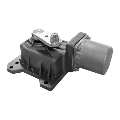
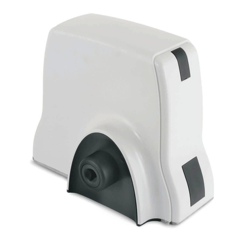
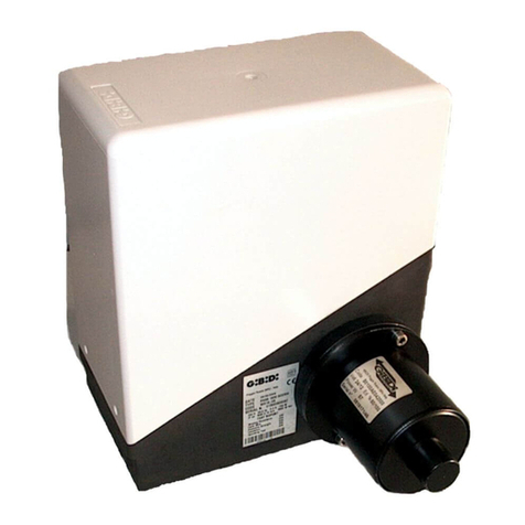
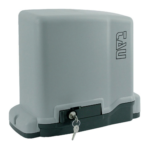
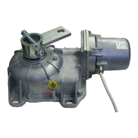
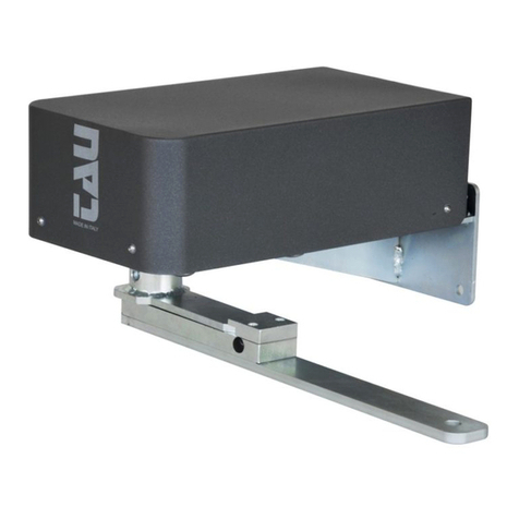
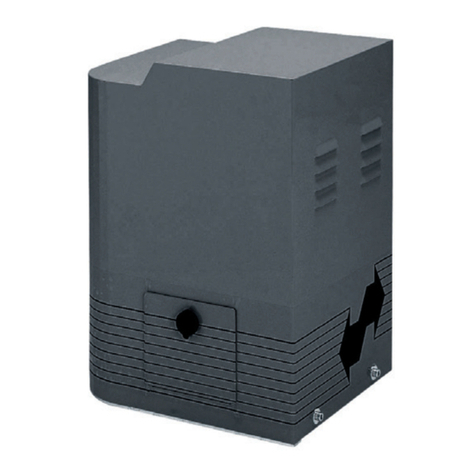
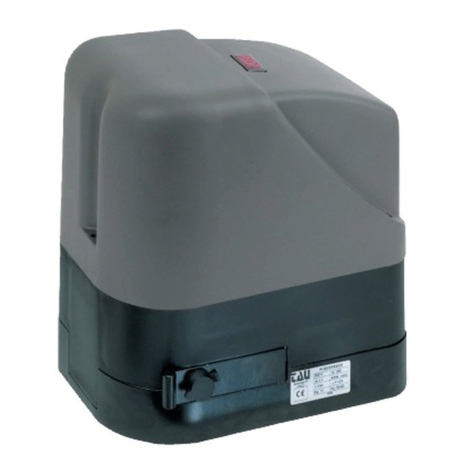
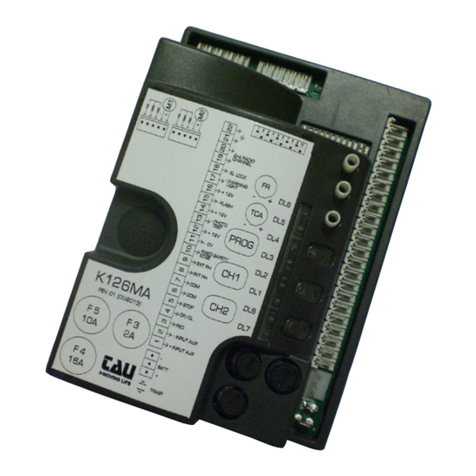
tau MASTER Series User manual

1
MANUALE D’USO E MANUTENZIONE
USE AND MAINTENANCE MANUAL
BEDIENUNGS - UND WARTUNGSANLEITUNG
MANUEL D’EMPLOI ET D’ENTRETIEN
MANUAL DE USO Y MANTENIMIENTO
MASTER
D_MNL0MASTER 17-02-2020 - Rev.35

2
FIG 6
FIG 13
FIG 14B
FIG 15B
c
2
1
2
5
5
5
5
66
3
4
7d
i
b
a
g
h
f
Fig. 1 Fig. 2 Fig. 3 Fig. 4
Fig. 5
TX
RX
TX
RX
230 Vac
400 Vac
MASTER18QR
MASTER-R
MASTER20QR
MASTER20QM
MASTER20T
50 mm
Fig. 6 Fig. 7
TASSELLO
EXPANSION BOLD
SPREIZDUBELN
VIS TAPONEE
TORNILLO TALADRADORE
PARAFUSOS DE FIXAÇÃO
CAVI
WIRES
KABELS
CABLES
CABLES
CABOS
GUAINA
SHEAT
HULLE
GAINES
FUNDA
SCAVO
EXCAVATION
GRABEN
CREUSEMENT
EXCAVACION
BURACO

3
FIG 6
FIG 13
FIG 14B
FIG 15B
195
100 100
60
95
64
Ø10,2
R20
3145
210
70
5560
390
36 159 159 36
60
195
Max. 40 mm
15 cm
10 - 20 mm
Fig. 8 Fig. 9
Fig. 10 Fig. 11
Fig. 13
SCAVO
EXCAVATION
GRABEN
CREUSEMENT
EXCAVACION
BURACO
CONTROPIASTRA
COUNTERPLATE
FUNDAMENTGE-
GENPLATTE
CONTRE-PLAQUE
CONTRAPLACA
BASE DE FIXAÇÃO
Fig. 12
Fig. 14A Fig. 15A
CAVI
WIRES
KABELS
CABLES
CABLES
CABOS
GUAINA
SHEAT
HULLE
GAINES
FUNDA
CANCELLO
GATE
TOR
PORTAIL
VERJA
PORTÃO
1
FIG 6
FIG 13
FIG 14B
FIG 15B

4
XX
2 mm
FIG 6
FIG 13
FIG 14B
FIG 15B
FIG 6
FIG 13
FIG 14B
FIG 15B
2 mm
Max.
60 mm
A
Fig. 14B Fig. 16
Fig. 17 Fig. 17B
Fig. 18
Fig. 15B
Fig. 19 Fig. 20
Fig. 21 Fig. 22
MOTORIDUTTORE
GEARMOTOR
GETRIEBEMOTOR
MOTOREDUCTEUR
MOTORREDUCTOR
MOTORREDUTOR
VITE
SCREW
SCHRAUBE
VIS
TORNILLO
PARAFUSOS
VITE
SCREW
SCHRAUBE
VIS - TORNILLO
PARAFUSOS
PATTINO
LIMIT
ENDGLEITBOCKE
PATIN
PATINO
PATIM
INGRANAGGIO
GEAR
ZAHNRAD
ENGRENAGE
ENGRANAJE
PINHÃO
CREMAGLIERA
RACK
ZAHNSTANGE
CREMAILLERE
CREMALLERA
CREMALHEIRA
CANCELLO
GATE
TOR
PORTAIL
VERJA
PORTÃO
PATTINO
LIMIT
ENDGLEITBOCKE
PATIN
PATINO
PATIM
CREMAGLIERA
RACK
ZAHNSTANGE
CREMAILLERE
CREMALLERA
CREMALHEIRA
CREMAGLIERA
RACK
ZAHNSTANGE
CREMAILLERE
CREMALLERA
CREMALHEIRA
Min. 17,5 mm
Max. 30 mm
103,75 mm
IMPORTANT:
OBSERVE THE MEASURES!

5
378 mm
390 mm
(min) 61 mm
(max) 94 mm
55 mm
60 mm
1
3
2
12345678
12345678
A
B
C
D
E
F
A2
FIG 31
FIG 32
12345678
12345678
A
B
C
D
E
F
A2
FIG 31
FIG 32
15 ÷ 18 mm
Fig. 23 Fig. 24
Fig. 25 Fig. 26
Fig. 27
Fig. 28
Fig. 30
INGRANAGGIO
GEAR
ZAHNRAD
ENGRENAGE
ENGRANAJE
PINHÃO
CREMAGLIERA
RACK
ZAHNSTANGE
CREMAILLERE
CREMALLERA
CREMALHEIRA
INGRANAGGIO
GEAR
ZAHNRAD
ENGRENAGE
ENGRANAJE
PINHÃO
CREMAGLIERA
RACK
ZAHNSTANGE
CREMAILLERE
CREMALLERA
CREMALHEIRA
CONTROPIASTRA
COUNTERPLATE
FUNDAMENTGE-
GENPLATTE
CONTRE-PLAQUE
CONTRAPLACA
BASE DE FIXAÇÃO
VITE
SCREW
SCHRAUBE
VIS
TORNILLO
PARAFUSOS
VITE
SCREW
SCHRAUBE
VIS
TORNILLO
PARAFUSOS
378 mm
10-15 mm
Fig. 29
SALDATURA
WELDING
SCHWEISSUNG
SOUDURE
SOLDADURA
SOLDADURA
ROTAIA
RAIL
SCHIENE
ORNIERE
CARRIL
SCAVO
EXCAVATION
GRABEN
CREUSEMENT
EXCAVACION
BURACO
ZANCA
BRACKET
BUGEL
PATTE
GRAPA
CANTONEIRA
TASSELLO
EXPANSION BOLD
SPREIZDUBELN
VIS TAPONEE
TORNILLO
TALADRADORE
PARAFUSOS DE FIXAÇÃO
Fig. 31
VITE
SCREW
SCHRAUBE
VIS
TORNILLO
PARAFUSOS
DADO
NUT
MUTTER
ECROU
TUERCA
PORCA
DADO
NUT
MUTTER
ECROU
TUERCA
PORCA
VITE
SCREW
SCHRAUBE
VIS
TORNILLO
PARAFUSOS
12345678
12345678
A
B
C
D
E
F
A2
FIG 31
FIG 32
Fig. 32

6
Italiano
Español
Português
English
Français
Deutsch
I dati riportati nel presente manuale sono puramente indicativi. La TAU si riserva il diritto di modicarli in qualsiasi momento.
La Casa costruttrice si riserva il diritto di apportare modiche o miglioramenti al prodotto senza alcun preavviso. Eventuali
imprecisioni o errori riscontrabili nel presente fascicolo, saranno corretti nella prossima edizione.
All’apertura dell’imballo vericare che il prodotto sia integro. Riciclare i materiali secondo la normativa vigente.
L’installazione del prodotto dovrà essere eettuata da personale qualicato. La Ditta costruttrice Tau declina ogni
responsabilità per danni derivanti a cose e/o persone dovuti ad un’eventuale errata installazione dell’impianto o la non
messa a Norma dello stesso secondo le vigenti Leggi (vedi Direttiva Macchine).
Los datos describidos en este manual son puramente indicativos. La TAU se reserva el derecho de modicarlos en cualquier
momento.
El Fabricante se reserva el derecho de modicar o actualizar el producto sin aviso previo. Posibles imprecisiones o errores en
este manual serán corregidos en la próxima edición.
Cuando abra el embalaje, controle que el producto esté íntegro. Recicle los materiales según la normativa vigente.
La instalación del producto tiene que ser efectuada por personal cualicado. El Fabricante Tau no se asume ninguna
responsabilidad por lesiones a personas o averías a cosas causadas por una instalación incorrecta del equipo o la por la
inobservancia de la normativa vigente (véase Directiva de Máquinas).
Os dados descritos neste manual são puramente indicativos. A TAU reserva-se o direito de o modicar a qualquer momento.
O fabricante reserva-se o direito de modicar ou actualizar o produto sem aviso prévio. Possíveis imprecisões ou erros no
presente manual serão corrigidos na próxima edição/revisão.
Ao abrir a embalagem certique-se que o produto está intacto. Recicle os materiais segundo as normas em vigor.
Este produto só pode ser instalado por um técnico qualicado. O fabricante TAU declina qualquer responsabilidade por
danos corporais ou materiais resultantes de uma eventual instalação incorrecta do equipamento ou a não conformidade
com a norma vigente (Ver Directiva de Máquinas).
The data described in this handbook are purely a guide. TAU reserves the right to change them in any moment.
The manufacturer reserves the right to modify or improve products without prior notice. Any inaccuracies or errors found in this
handbook will be corrected in the next edition.
When opening the packing please check that the product is intact. Please recycle materials in compliance with current regulations.
This product may only be installed by a qualied tter. The manufacturer declines all liability for damage to property
and/or personal injury deriving from the incorrect installation of the system or its non-compliance with current law (see
Machinery Directive).
Les données décrites dans ce manual sont purement indicatives. La TAU se réserve le droit de les modier à n’importe quel
moment. Le Constructeur se réserve le droit d’apporter des modications ou des améliorations au produit sans aucun préavis.
Les éventuelles imprécisions ou erreurs présentes dans ce fascicule seront corrigées dans la prochaine édition.
À l’ouverture de l’emballage, vérier que le produit est intact. Recycler les matériaux suivant les normes en vigueur.
L’installation du produit devra être eectuée par du personnel qualié. Tau décline toute responsabilité pour les
dommages aux choses et/ou personnes dus à une éventuelle installation erronée de l’automatisme ou à la non-mise
aux normes suivant les lois en vigueur (voir Directive Machines).
Die beschriebenen Daten in der vorliegenden Betriebsanleitung sind rein indikativ. TAU behält sich vor, diese in jedem Moment
zu modizieren. Der Hersteller behält sich das Recht vor, ohne vorherige Benachrichtung Änderungen oder Verbesserungen
am Produkt anzubringen. Ungenauigkeiten oder Fehler, die in der vorliegenden Ausgabe festgestellt werden, werden in der
nächsten Ausgabe berichtigt. Beim Önen der Verpackung prüfen, dass das Produkt keine Schäden aufweist. Die Materialien
nach den gültigen Vorschriften recyclen.
Die Installation des Produktes muss von Fachpersonal ausgeführt werden. Die Herstellerrma TAU übernimmt keinerlei
Haftung für Personen- und/oder Sachschäden aufgrund einer falschen Installation der Anlage oder der Nichtkonformität
derselben mit den gültigen Gesetzen (siehe Maschinenrichtlinie).

7
AVVERTENZE PER L’INSTALLATORE
OBBLIGHI GENERALI PER LA SICUREZZA
1) Leggere attentamente le istruzioni prima di procedere
all’installazione, in quanto forniscono importanti indica-
zioni concernenti la sicurezza, l’installazione, l’uso e la ma-
nutenzione. Una errata installazione o un errato uso del
prodotto può portare a gravi danni alle persone.
2) I materiali dell’imballaggio (plastica, polistirolo, ecc.) non devo-
no essere lasciati alla portata dei bambini in quanto potenziali
fonti di pericolo.
3) Conservare le istruzioni per riferimenti futuri.
4) Questo prodotto è stato progettato e costruito esclusivamente
per l’utilizzo indicato in questa documentazione. Qualsiasi altro
utilizzo non espressamente indicato potrebbe pregiudicare l’in-
tegrità del prodotto e/o rappresentare fonte di pericolo.
5) TAU declina qualsiasi responsabilità derivata dall’uso improprio
o diverso da quello per cui l’automatismo è destinato.
6) Non installare il prodotto in ambiente e atmosfera esplosivi.
7) Gli elementi costruttivi meccanici devono essere in accordo con
quanto stabilito dalle Norme EN 12604 e EN 12605. Per i Paesi
extra-CEE, oltre ai riferimenti normativi nazionali, per ottenere
un livello di sicurezza adeguato, devono essere seguite le Nor-
me sopra riportate.
8) TAU non è responsabile dell’inosservanza della Buona Tecnica
nella costruzione delle chiusure da motorizzare, nonché delle
deformazioni che dovessero intervenire nell’utilizzo.
9) L’installazione deve essere eettuata nell’osservanza delle Nor-
me EN 12453 e EN 12445.
Per i Paesi extra-CEE, oltre ai riferimenti normativi nazionali,
per ottenere un livello di sicurezza adeguato, devono essere
seguite le Norme sopra riportate.
10) Prima di eettuare qualsiasi intervento sull’impianto, togliere
l’alimentazione elettrica e scollegare le batterie.
11) Prevedere sulla rete di alimentazione dell’automazione un
interruttore onnipolare con distanza d’apertura dei contatti
uguale o superiore a 3 mm. È consigliabile l’uso di un magneto-
termico da 6A con interruzione onnipolare.
12) Vericare che a monte dell’impianto vi sia un interruttore die-
renziale con soglia da 0,03 A.
13) Vericare che l’impianto di terra sia realizzato a regola d’arte e
collegarvi le parti metalliche della chiusura.
INSTALLATION WARNINGS
GENERAL SAFETY REQUIREMENTS
1) Carefully read all instructions before installation, as they
provide important instructions regarding the safety, instal-
lation, operation and maintenance. Incorrect installation
or use of the product may lead to serious physical injury.
2) Never leave packaging materials (plastic, polystyrene etc.) with-
in the reach of children as they constitute a potential hazard.
3) Keep the instructions in a safe place for future consultation.
4) This product has been designed and constructed exclusively
for the use specied in this documentation. Any other use not
specied herein may impair product integrity and/or constitute
a hazard.
5) TAU declines all liability for improper use or use other than as
specied for this automation.
6) Never install the product in explosive atmospheres.
7) The mechanical elements must comply with the requirements
as stated in the standards EN 12604 and EN 12605. For non
European member states, in addition to the national reference
standards, the above-mentioned standards must be observed
to ensure an adequate level of safety.
8) TAU is not responsible for failure to observe Good Practice in
construction of the gates/doors to be power-operated, nor any
deformations occurring during use.
9) Installation must be performed in compliance with the stand-
ards EN 12453 and EN 12445.
For non European member states, in addition to the national
reference standards, the above-mentioned standards must be
observed to ensure an adequate level of safety.
10) Before performing any operations on the system, disconnect
from the mains and detach the batteries.
11) On the automation power line, install a device for disconnec-
tion from the power mains with a gap between contacts equal
to or greater than 3 mm. Use of a 6A thermal magnetic circuit
breaker with multi-pole switch is recommended.
12) Check upline of the system that there is a residual current cir-
cuit breaker with a threshold of 0.03 A.
13) Ensure that the earthing system is to professional standards
and connected to the metal section of the gate/door.
14) I dispositivi di sicurezza (norma EN 12978) permettono di pro-
teggere eventuali aree di pericolo da Rischi meccanici di mo-
vimento, come ad es. schiacciamento, convogliamento, cesoia-
mento.
15) Per ogni impianto è consigliato l’utilizzo di almeno una segna-
lazione luminosa nonché di un cartello di segnalazione ssato
adeguatamente sulla struttura dell’insso, oltre ai dispositivi
citati al punto 14.
16) TAU declina ogni responsabilità ai ni della sicurezza e del buon
funzionamento dell’automazione in caso vengano utilizzati
componenti dell’impianto non di produzione TAU.
17) Per la manutenzione utilizzare esclusivamente parti originali
TAU.
18) Non eseguire alcuna modica sui componenti facenti parte del
sistema d’automazione.
19) L’installatore deve fornire tutte le informazioni relative al fun-
zionamento manuale del sistema in caso di emergenza e con-
segnare all’Utente utilizzatore dell’impianto la “Guida Utente”
allegata al prodotto.
20) Non permettere ai bambini o persone di sostare nelle vicinanze
del prodotto durante il funzionamento.
21) Tenere fuori dalla portata dei bambini radiocomandi o qualsia-
si altro datore di impulso, per evitare che l’automazione possa
essere azionata involontariamente.
22) Il transito tra le ante deve avvenire solo a cancello completa-
mente aperto.
23) L’utente utilizzatore deve astenersi da qualsiasi tentativo di ri-
parazione o d’intervento diretto e rivolgersi solo a personale
qualicato.
24) Manutenzione: eettuare almeno semestralmente la verica
funzionale dell’impianto, con particolare attenzione all’ecien-
za dei dispositivi di sicurezza (compresa, ove previsto, la forza
di spinta dell’operatore) e di sblocco.
25) Tutto quello che non è previsto espressamente in queste istru-
zioni non è permesso.
Consigliamo di riporre tutta la documentazione relativa all’im-
pianto all’interno o nelle immediate vicinanze della centralina
14) The safety devices (standard EN 12978) enable the protec-
tion of danger areas from risks associated with mechanical
movements such as crushing, dragging and shearing.
15)
The use of at least one luminous indicator is recommended for
each system, as well as a warning notice xed suitably to the frame
structure, in addition to the devices specied in point 14.
16) TAU declines all liability for the safety and ecient operation of
the automation in the event of using system components not
produced by TAU.
17) For maintenance, use exclusively original TAU parts.
18) Never modify components that are part of the automation sys-
tem.
19) The installer must provide all information regarding manual op-
eration of the system in the event of an emergency and supply
the system User with the “User Guide” enclosed with the prod-
uct.
20) Never allow children or other persons to stay in the vicinity of
the product during operation.
21) Keep all radio controls or other pulse supplier device out of the
reach of children to prevent inadvertent activation of the auto-
mation.
22) Transit through the leaves is allowed only when the gate is fully
open.
23) The user must never attempt to repair or intervene directly on
the product; always contact qualied personnel for assistance.
24) Maintenance: at least every six months, make a general check
of the system, with special reference to the eciency of the
safety devices (including, when envisaged, the operator thrust
force) and release mechanisms.
25) All actions not expressly envisaged in these instructions are
strictly prohibited.
All documentation related to the system should be kept inside or
in the immediate vicinity of the control unit.
ITALIANO
ENGLISH

8
HINWEISE FÜR DEN INSTALLATEUR
ALLGEMEINE PFLICHTEN BEZÜGLICH DER SICHER-
HEIT
1) Lesen Sie vor der Installation genau die Anweisungen, da
sie wichtige Hinweise bezüglich der Sicherheit, der Instal-
lation, der Bedienung sowie der Wartung enthalten. Eine
falsche Installation oder eine falsche Anwendung des Pro-
dukts kann zu schweren Verletzungen führen.
2) Das Verpackungsmaterial (Kunststo, Polystyrol usw.) darf
nicht in der Reichweite von Kindern aufbewahrt werden, da es
eine mögliche Gefahrenquelle darstellt.
3) Die Anleitungen für einen späteren Bedarf aufbewahren.
4) Dieses Produkt wurde ausschließlich für den in diesen Unter-
lagen angegebenen Zweck entwickelt und gebaut. Jede ande-
re nicht ausdrücklich angegebene Nutzung könnte die Unver-
sehrtheit des Produkts beeinträchtigen und/oder eine Gefah-
renquelle darstellen.
5) TAU lehnt jede Verantwortung für einen unsachgemäßen oder
nicht den Angaben entsprechenden Gebrauch der Automatisie-
rung ab.
6) Das Produkt nicht in EX-gefährdeter Atmosphäre oder Umge-
bung installieren.
7) Die mechanischen Bauteile müssen mit den Vorschriften der
Norm EN 12604 und EN 12605 übereinstimmen. In außereuro-
päischen Ländern müssen außer den nationalen Vorschriften
auch die oben genannten Normen befolgt werden, um eine
ausreichende Sicherheitsstufe zu erreichen.
8) TAU übernimmt keinerlei Haftung im Falle von nicht fachge-
rechter Konstruktion der Toröner oder im Falle von Verfor-
mungen derselben während des Gebrauchs.
9) Die Installation muss bei Einhaltung der Normen EN 12453 und
EN 12445 vorgenommen werden. In außereuropäischen Län-
dern müssen außer den nationalen Vorschriften auch die oben
genannten Normen befolgt werden, um eine ausreichende Si-
cherheitsstufe zu erreichen.
10) Vor der Ausführung beliebiger Arbeiten an der Anlage die
Stromspeisung entfernen und die Batterien abtrennen.
11)
Im Speisungsnetz der Automatisierung einen allpoligen Schalter
mit einer Önungsdistanz der Kontakte gleich oder über 3 mm
vorsehen. Wir empfehlen, einen 6A-Magnetthermoschalter mit ei-
ner allpoligen Unterbrechung zu verwenden.
AVERTISSEMENTS POUR L’INSTALLATEUR
CONSIGNES GÉNÉRALES DE SÉCURITÉ
1) Lire attentivement les instructions avant de procéder à
l’installation, dans la mesure où elles fournissent des indi-
cations importantes concernant la sécurité, l’installation,
l’utilisation et la maintenance. Une installation incorrecte
ou une utilisation impropre du produit peut entraîner de
graves dommages aux personnes.
2) Les matériaux de l’emballage (plastique, polystyrène expansé,
etc.) ne doivent pas être laissés à la portée des enfants dans la
mesure où ils sont une source potentielle de danger.
3) Conserver les instructions pour toute consultation future.
4) Ce produit a été conçu et construit exclusivement pour l’utilisa-
tion indiquée dans cette documentation. Toute autre utilisation
qui n’est pas expressément indiquée peut compromettre l’inté-
grité du produit et/ou représenter une source de danger.
5) TAU décline toute responsabilité dérivant de l’utilisation im-
propre ou diérente de celle à laquelle l’automatisme est des-
tiné.
6) Ne pas installer le produit dans une atmosphère et un environ-
nement explosifs.
7) Les éléments mécaniques doivent être conformes aux normes
EN 12604 et EN 12605. Pour les pays extra-CEE, en plus des
normes relatives à chaque pays, pour obtenir un niveau de
sécurité adéquat, il faut respecter également les normes sus-
mentionnées.
8) TAU n’est pas responsable de la non-observation des règles de
l’art dans la construction des fermetures à motoriser, ainsi que
des déformations qui pourraient se vérier lors de l’utilisation.
9) L’installation doit être eectuée dans le respect des normes
EN 12453 et EN 12445. Pour les pays extra-CEE, en plus des
normes relatives à chaque pays, pour obtenir un niveau de
sécurité adéquat, il faut respecter également les normes sus-
mentionnées.
10) Avant d’eectuer n’importe quelle intervention sur l’installation,
couper l’alimentation électrique et déconnecter les batteries.
11)
Prévoir sur le réseau d’alimentation de l’automatisation un inter-
rupteur omnipolaire avec distance d’ouverture des contacts égal
ou supérieur à 3 mm. Il est conseillé d’utiliser un interrupteur ma-
gnétothermique de 6A avec interruption omnipolaire.
12) Vérier qu’en amont de l’installation il y a un interrupteur dié-
rentiel avec seuil de 0,03 A.
13) Vérier que l’installation de mise à la terre est réalisée dans les
règles de l’art et y raccorder les parties métalliques de la ferme-
12) Prüfen, ob hinter der Anlage ein Dierenzialschalter mit max.
0,03 A vorliegt.
13) Prüfen, ob die Erdung fachgerecht ausgeführt wurde und die
Metallteile des Toröners daran anschließen.
14) Die Sicherheitsvorrichtungen (Norm EN 12978) ermöglichen
den Schutz eventueller Gefahrenbereiche vor mechanischen
Bewegungsrisiken, wie z.B. Einquetschen, Mitziehen, Schnei-
den.
15) Für jede Anlage sind die Verwendung mindestens einer Leucht-
anzeige und eines Hinweisschilds, das am Rahmen befestigt
wird, sowie die Vorrichtungen laut Punkt 14 empfehlenswert.
16) TAU lehnt jede Haftung hinsichtlich der Sicherheit und der
Funktionstüchtigkeit der Automatisierung ab, falls nicht von
TAU hergestellte Anlagenteile verwendet werden.
17) Zur Instandhaltung ausschließlich TAU-Originalersatzteile ver-
wenden.
18) Keine Änderung an Bestandteilen des Automatisierungssys-
tems ausführen.
19) Der Installateur muss alle Informationen bezüglich des manu-
ellen Betriebs des Systems im Notfall weitergeben und dem An-
wender der Anlage die dem Produkt beigelegte „Bedienungsan-
leitung“ aushändigen.
20) Kindern oder anderen Personen nicht erlauben, während des
Betriebs in der Nähe des Produkts zu bleiben.
21) Fernsteuerungen oder andere Impulsgeber außerhalb der
Reichweite von Kindern aufbewahren, um zu vermeiden, dass
die Automatisierung ungewollt betätigt wird.
22) Der Durchgang darf nur bei stehender Automatisierung erfol-
gen.
23) Der Durchgang oder die Durchfahrt zwischen den Flügeln darf
lediglich bei vollständig geönetem Tor erfolgen.
24) Wartung: Mindestes alle sechs Monate die Funktionstüchtigkeit
der Anlage prüfen, mit besonderer Beachtung der Ezienz der
Sicherheitsvorrichtungen (einschließlich der Schubkraft der Au-
tomatisierung, wo vorhanden) und der Entriegelungsvorrich-
tungen.
25) Alles nicht ausdrücklich in diesen Anweisungen vorgesehene ist
unzulässig.
Wir empfehlen, die ganzen Unterlagen bezüglich der Anlage inner-
halb oder in der Nähe des Steuergeräts aufzubewahren.
ture.
14) Les dispositifs de sécurité (norme EN 12978) permettent de
protéger les éventuelles zones de danger contre les Risques
mécaniques de mouvement, comme par exemple l’écrase-
ment, l’entraînement, le cisaillement.
15) Pour chaque installation il est conseillé d’utiliser au moins une
signalisation lumineuse ainsi qu’un panneau de signalisation
xé de manière adéquate sur le bâti de la porte ou du portail,
en plus des dispositifs cités au point 14.
16)
TAU décline toute responsabilité aux ns de la sécurité et du bon
fonctionnement de l’automatisation en cas d’utilisation de compo-
sants de l’installation qui ne sont pas produits par TAU.
17) Pour la maintenance, utiliser exclusivement des pièces d’ori-
gine TAU.
18) N’eectuer aucune modication sur les composants faisant
partie du système d’automatisation.
19) L’installateur doit fournir toutes les informations relatives au
fonctionnement manuel du système en cas d’urgence et re-
mettre à l’utilisateur de l’installation le « Guide de l’utilisateur »
joint au produit.
20) Ne pas permettre aux enfants ou aux personnes de stationner
à proximité du produit durant le fonctionnement.
21) Conserver hors de portée des enfants les radiocommandes ou
tout autre dispositif émettant des impulsions, pour éviter que
l’automation puisse être actionnée involontairement.
22) Le transit entre les vantaux ne doit avoir lieu que lorsque le
portail est complètement ouvert.
23) L’utilisateur doit s’abstenir de toute tentative de réparation ou
d’intervention directe et s’adresser uniquement à du personnel
qualié.
24) Maintenance : eectuer au moins une fois par semestre le
contrôle de fonctionnement de l’installation, avec une attention
particulière pour les dispositifs de sécurité (incluant, quand
c’est prévu, la force de poussée de l’opérateur) et de débrayage.
25) Tout ce qui n’est pas expressément prévu dans ces instructions
n’est pas autorisé.
Nous conseillons de conserver toute la documentation relative
à l’installation à l’intérieur ou à proximité de la logique de com-
mande.
DEUTSCHFRANÇAIS

9
ADVERTENCIAS PARA EL INSTALADOR
OBLIGACIONES GENERALES PARA LA SEGURIDAD
1) Lea atentamente las instrucciones antes de efectuar la instala-
ción, ya que proporcionan indicaciones importantes acerca de
la seguridad, la instalación, el uso y el mantenimiento. Una ins-
talación o un uso erróneo del producto puede provocar lesiones
graves a las personas.
2) Los materiales del embalaje (plástico, poliestireno, etc.) no tienen que
dejarse nunca al alcance de los niños ya que son fuentes potenciales
de peligro.
3) Conserve las instrucciones para referencias futuras.
4) Este producto se ha diseñado y construido de forma exclusiva para el
uso que se indica en esta documentación. Cualquier otro uso que no se
haya indicado de forma explícita podría comprometer la integridad del
producto y/o representar una fuente de peligro.
5) TAU declina cualquier responsabilidad que derive de un uso impropio o
diverso del uso para el que se ha previsto el automatismo.
6) No instale el producto en un ambiente y/o una atmósfera explosivos.
7) Los elementos mecánicos de la construcción tienen que coincidir con
lo que establecen las Normas EN 12604 y EN 12605. Para los países
extra-CEE, además de las referencias normativas nacionales, para
obtener un nivel de seguridad adecuado, tienen que seguirse las
Normas citadas en el punto anterior.
8) TAU no es responsable por el incumplimiento de la Buena Técnica en
la construcción de los cierres a motorizar, así como de las deforma-
ciones que pudieran provocarse con el uso.
9) La instalación se tiene que efectuar cumpliendo con las Normas EN
12453 y EN 12445. Para los países extra-CEE, además de las referen-
cias normativas nacionales, para obtener un nivel de seguridad ade-
cuado, tienen que seguirse las Normas citadas en el punto anterior.
10) Antes de efectuar cualquier intervención sobre la instalación, saque
la alimentación eléctrica y desconecte las baterías.
11) Es necesario prever sobre la red de alimentación de la automatiza-
ción un interruptor omnipolar con distancia de apertura de los con-
tactos igual o superior a 3 mm. Se aconseja la utilización de un mag-
netotérmico de 6A con interrupción omnipolar.
12) Compruebe que la parte inicial de la instalación disponga de un inte-
rruptor diferencial con un umbral de 0,03 A.
13) Compruebe que la instalación de tierra esté realizada con todas las
de la ley y conecte en ella las partes metálicas del cierre.
AVISO AO INSTALADOR
NORMAS GERAIS DE SEGURANÇA
1) Leia atentamente as instruções antes de proceder à instalação,
na medida em que estas fornecem indicações importantes re-
lativas à segurança, à instalação, à utilização e à manutenção.
Uma instalação ou utilização incorrectas podem traduzir-se em
sérios riscos para as pessoas.
2) Os materiais da embalagem (plástico, poliestireno, etc.) não devem
ser deixados ao alcance das crianças na medida em que constituem
uma potencial fonte de perigo.
3) Guardar o manual do utilizador para qualquer consulta futura.
4) Este produto foi concebido e construído exclusivamente para o m
indicado neste documento. Qualquer outra utilização que não a ex-
pressamente indicada pode comprometer a integridade do produto
e/ou representar uma potencial fonte de perigo.
5) TAU declina qualquer responsabilidade derivada de uma utilização
imprópria ou diferente daquela a que o automatismo se destina.
6) Não instalar o produto numa atmosfera ou ambiente explosivo.
7) Os elementos mecânicos devem estar de acordo com o estabelecido
nas normas EN 12604 e EN 12605. Para os países extra CEE, além das
normas nacionais aplicáveis, devem ser seguidas as normas acima
mencionadas de modo a garantir um adequado nível de segurança.
8) A TAU não é responsável pela não observação de boas práticas na
construção do ponto de acesso a automatizar, nem pelas defor-
mações que se possam vericar aquando da sua utilização.
9) A instalação deve ser realizada em conformidade com as normas EN
12453 e EN12445. O nível de segurança da automação deve ser C +
D.
10) Antes de iniciar qualquer tipo de intervenção na instalação, desligar a
alimentação da rede eléctrica e desconectar a bateria.
11) É necessário instalar na rede de alimentação da automação um dis-
juntor omnipolar, com uma distância de abertura entre contactos,
igual ou superior a 3mm.
Recomenda-se o uso de um disjuntor magnetotérmico de 6A com
corte omnipolar.
12) Vericar se a montante da instalação existe um disjuntor diferencial
com uma sensibilidade de 30 mA.
13) Assegurar que o aterramento do sistema (ligação terra) está confor-
me a boa prática prossional e ligado à parte metálica do portão.
14) O automatismo é fornecido com um dispositivo de segurança intrínseco
14) Los dispositivos de seguridad (norma EN 12978) permiten proteger
eventuales áreas de peligro de Riesgos mecánicos de movimiento,
como por ejemplo aplastamiento, arrastre y cizalladura.
15) Se aconseja la utilización, en cada instalación, de por lo menos un
aviso luminoso, así como un cartel de aviso jado de forma adecuada
en la estructura del cerramiento, además de los dispositivos citados
en el punto 14.
16) TAU declina cualquier responsabilidad respecto a la seguridad y el
buen funcionamiento de la automatización en caso de que se utili-
cen componentes de la instalación que no hayan sido fabricados por
TAU.
17) Para el mantenimiento utilice de forma exclusiva piezas de recambio
originales TAU.
18) No efectúe ninguna modicación en los componentes que forman
parte del sistema de automatización.
19) El instalador tiene que suministrar todas las informaciones referen-
tes al funcionamiento manual del sistema en caso de emergencia y
entregar al usuario de la instalación la “Guía del Usuario” que se ad-
junta al producto.
20) No permita a los niños u otras personas que se detengan en los alre-
dedores del producto durante su funcionamiento.
21) Mantenga fuera del alcance de los niños radiocontroles o cualquier
otro elemento similar para evitar que la automatización pueda accio-
narse de forma involuntaria.
22) Sólo puede transitarse entre las hojas si la cancela está completa-
mente abierta.
23) El usuario tiene que evitar cualquier intento de reparación o de inter-
vención directa y tiene que ponerse en contacto para ello sólo con
personal especializado.
24) Mantenimiento: efectúe por lo menos cada semestre la com-
probación funcional de la instalación, prestando una atención
especial a la eciencia de los dispositivos de seguridad (com-
prendida, donde está previsto, la fuerza de empuje del opera-
dor) y de desbloqueo.
25) Todo lo que no se ha previsto de forma explícita en estas instruccio-
nes no está permitido.
Aconsejamos guardar toda la documentación referente a la instalación
dentro o cerca de la centralita.
de anti-esmagamento através do controlo do binário. Não obstante, é
necessário vericar a sensibilidade do seu funcionamento segundo o
previsto nas normas indicadas no ponto I.
15) Os dispositivos de segurança (standard EN 12978) permitem prote-
ger zonas de perigo/sensíveis contra riscos associados a movimentos
mecânicos tais como esmagamento, arrastamento e cisalhamento.
16) Em cada instalação é aconselhada a utilização de pelo menos uma
sinalização luminosa, assim como uma placa de informação adequa-
damente xada à estrutura da automação, em conjunto com os ou-
tros dispositivos já citados no ponto O.
17) O fabricante do automatismo declina qualquer responsabilidade
em caso de instalação de componentes incompatíveis em termos
de segurança e bom funcionamento. Para eventual reparação ou
substituição dos produtos, devem ser utilizadas unicamente peças
de substituição originais TAU.
18) Para efectuar a manutenção do sistema, utilizar exclusivamente
peças originais TAU.
19) Não efectuar nenhuma modicação em elementos que façam parte
do sistema do automatismo.
20) O instalador deve fornecer toda a informação em relação à operação
manual do sistema em caso de emergência ou falha no fornecimen-
to de energia eléctrica, e entregar ao utilizador nal o “Manual do Uti-
lizador” que acompanha o produto.
21) Não permitir que pessoas ou crianças permaneçam na vizinhança do
produto durante o seu funcionamento.
22) Manter fora do alcance das crianças todos os comandos/emissores
ou outros dispositivos geradores de impulsos, de modo a impedir
activação involuntária da automação.
23) O trânsito através das folhas do portão só deve ser feito após este
estar completamente aberto.
24) O utilizador deve abster-se de qualquer tentativa de reparação ou
intervenção directa e recorrer a um técnico especializado.
25) Tudo o que não estiver expressamente previsto nestas instruções
deve entender-se como não permitido.
Aconselha-se que a documentação relacionada com o sistema esteja
guardada no interior ou na proximidade da caixa de protecção da uni-
dade de controlo.
ESPAÑOL
PORTUGUÊS

10
MASTER-R
Motoriduttore per
cancelli no a 1200
Kg, motore 24V,
quadro elettrico
incorporato.
Gearmotor for
gates up to 1200
Kg, 24V motor,
built-in control unit.
Getriebemotor
für Tore bis 1200
Kg, 24V Motor, mit
eingebauter Steu-
erzentrale.
Motoréducteur
pour portails
jusqu’à 1200 Kg,
moteur 24V, cen-
trale incorporée.
Motorreductor
para verjas de has-
ta 1200 Kg, motor
de 24V, central
incorporada.
Motorredutor para
portões de correr
até 1200 Kg. Motor
24 V e unidade de
controlo incorpo-
rada.
MASTER18QR
Motoriduttore per
cancelli no a 1800
Kg, motore 18V,
quadro elettrico
incorporato.
Gearmotor for
gates up to 1800
Kg, 18V motor,
built-in control unit.
Getriebemotor
für Tore bis 1800
Kg, 18V Motor, mit
eingebauter Steu-
erzentrale.
Motoréducteur
pour portails
jusqu’à 1800 Kg,
moteur 18V, cen-
trale incorporée.
Motorreductor
para verjas de has-
ta 1800 Kg, motor
de 18V, central
incorporada.
Motorredutor para
portões de correr
até 1800 Kg. Motor
18 V e unidade de
controlo incorpo-
rada.
MASTER20QR
Motoriduttore per
cancelli no a 2000
kg, motore 230V
con quadro elettri-
co incorporato.
Gearmotor for
gates up to 2000
Kg, 230V motor,
built-in control unit.
Getriebemotor für
Tore bis 2000 Kg,
230V Motor, mit
eingebauter Steu-
erzentrale.
Motoréducteur
pour portails
jusqu’à 2000 Kg,
moteur 230V, cen-
trale incorporée.
Motorreductor
para verjas de has-
ta 2000 Kg, motor
de 230V, centrale
incorporada.
Motorredutor para
portões de correr
até 2000 Kg. Motor
230 V e unidade de
controlo incorpo-
rada.
MASTER20QM
Motoriduttore
per cancelli no a
2000 kg, motore
230V con quadro
elettrico incorpo-
rato e ne corsa
magnetici
Gearmotor for
gates up to 2000
Kg, 230V motor,
built-in control unit
and magnetic limit
switches.
Getriebemotor
für Tore bis 2000
Kg, 230V Motor,
mit eingebauter
Steuerzentrale
und Magnetische
Endschalter.
Motoréducteur
pour portails
jusqu’à 2000 Kg,
moteur 230V,
centrale incorporée
et n de course
magnétiques.
Motorreductor
para verjas de has-
ta 2000 Kg, motor
de 230V, centrale
incorporada y nal
de recorridos mag-
néticos.
Motorredutor para
portões de correr
até 2000 Kg. Motor
230 V, unidade de
controlo incorpora-
da e ns de curso
magnéticos.
MASTER20T
Motoriduttore per
cancelli no a 2000
kg, motore 400V tri-
fase, senza quadro
elettrico.
Gearmotor for
gates up to 2000
Kg, 400V three-
phase motor, with-
out a control unit.
Getriebemotor für
Tore bis 2000 Kg,
400V dreiphasig
Motor, mit einge-
bauter Steuerzen-
trale.
Motoréducteur
pour portails
jusqu’à 2000 Kg,
moteur 400V
triphasé, sans
centrale.
Motorreductor
para verjas de has-
ta 2000 Kg, motor
de 400V trifásico,
sin centrale de
mando.
Motorredutor para
portões de correr
até 2000 Kg. Motor
400 V trifásico, sem
unidade de contro-
lo.
DESCRIZIONE, MODELLI E CARATTERISTICHE - DESCRIPTION, MODELS AND CHARACTERISTICS
BASCHREIBUNG, MODELLE UND MERKMALE - DESCRIPTION, MODÈLES ET CARACTÉRISTIQUES
DESCRIPCIÓN, MODELOS Y CARACTERÍSTICAS - DESCRIÇÃO, MODELOS E CARACTERÍSTICAS
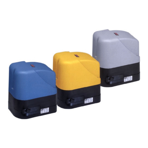
I - Imotoriduttori della serie MASTER sono stati progettati per automatizzare qualsiasi tipo di cancello scorrevole ad uso residenziale,
condominiale o industriale, con ante no a 2000 Kg. Non ore un elevato grado di sicurezza contro i tentativi di intrusione e/o
erazione. SI FA ESPRESSO DIVETO DI UTILIZZARE L’APPARECCHIO PER SCOPI DIVERSI O IN CIRCOSTANZE DIVERSE DA QUELLE
MENZIONATE.
GB - The MASTER series of gearmotors has been designed to automate any kind of sliding gate for residential, condominium or industrial
use, with leafs weights of up to 2000 kg. It is not intended as a high degree security deterrent against intrusion attempts and/or
tampering. IT IS ALSO EXPRESSED THAT THE APPARATUS MUST NOT BE USED UNDER ANY CIRCUMSTANCE OR FOR ANY PURPOSE
OTHER THAN THOSE STATED.
D - Die Getriebemotoren der Serie MASTER wurden für die Automatisierung von jedem Schiebetortyp mit Torügelgewicht bis 2000 kg gee-
ignet für den Privaten so wie für den Industriellen bereich. Sie bietet keinen Hochsicherheitsgrad gegen Eindringen- und/oder Ein-
bruchversuchen an. ES IST AUSDRÜCKLICH VERBOTEN, DAS GERÄT ZU ANDEREN ZWECKEN ODER UNTER ANDEREN UMSTÄNDEN
ALS ERWÄHNT ZU VERWENDEN.
F - Les motoréducteurs de la série MASTER ont été projetés pour automatiser n’importe quel type de portail coulissant à usage résidentiel,
collectif ou industriel, pesant jusqu’à 2000 Kg. Il n’assure pas un niveau élevé de sécurité contre les tentatives d’intrusion et/ou
d’eraction. IL EST FORMELLEMENT INTERDIT D’UTILISER L’APPAREIL DANS DES BUTS DIFFÉRENTS OU DANS DES CIRCONSTANCES
DIFFÉRENTES DE CELLES QUI SONT MENTIONNÉES.
E - Los motorreductores de la serie MASTER han sido diseñados para automatizar cualquier tipo de cancela decorredera para uso residencial,
comunitario o industrial, con hojas de hasta 2000 Kg. No ofrece un alto grado de seguridad contra los intentos de intrusión y/o robo.
QUEDA TERMINANTEMENTE PROHIBIDO UTILIZAR EL EQUIPO PARA FINALIDADES DISTINTAS O EN CIRCUNSTANCIAS DISTINTAS
DE LAS QUE SE INDICAN.
PT - Os motorredutores da série MASTER foram concebidos para automatizar qualquer tipo de portão de correr até 2000 Kg, para aplicação
residencial, condomínio ou industrial. Não oferece um alto grau de segurança contra tentativas de invasão e/ou arrombamento.
É EXPRESSAMENTE PROIBIDO UTILIZAR O APARELHO PARA FINALIDADES OU CIRCUNSTÂNCIAS DIFERENTES DAS MENCIONADAS
NESTE DOCUMENTO.

11
DATI TECNICI - TECHNICAL DATA - DONNÉES TECHNIQUES - TECHNISCHE DATEN - DATOS TÉCNICOS
MASTER-R
MASTER18QR
MASTER20QR
MASTER20QM
MASTER20T
Frequenza - Frequency - Frequenz -
Fréquence - Frecuencia - Frequência 50 - 60 Hz
Alimentazione - Power - Stromversorgung
- Alimentation - Alimentación -
Alimentação 230V AC 400V AC
Motore - Motor - Motor - Moteur -
Motor 24V DC 18V DC 230V AC 400V AC
Three-phase
Condensatore - Condenser -
Kondensator - Condensateur -
Condensador - Condensador
-16 µf -
Corrente assorbita - Absorbed current - Stro-
maufnahme -
Courant absorbé -
Corriente absorbida - Corrente absorvida
1,8 A 1,6 A 3,4 A 3,7 A
Potenza assorbita - Absorbed power - Leistung-
saufnahme -
Puissance absorbée -
Potencia absorbida - Potência absorvida 360 W 360 W 550 W 1000 W
Spinta max. - Max. thrust -
Max. Schub - Poussée max. -
Empuje máx.- Força máx. 1300 N 1500 N 1890 N
Velocità anta - Leaf speed - Flügelgeschwindig-
keit -
Vitesse du vantail -
Velocidad hoja - Velocidade da folha
24 m/min (opening)
14 m/min (closing) 14 m/min 10,5 m/min 10,5 m/min
Grado di protezione - Protection level -
Schutzart - Degré de protection -
Grado de protección - Grau de protecção IP 54
Ciclo di lavoro - Work cycle -
Arbeitszyklus - Cycle de travail -
Ciclo de trabajo - Frequência de utilização 100 % 40 % 58 %
Temperatura di esercizio - Operating tempera-
ture -
Betriebstemperatur -
Temperature de fonctionnement -
Temperatura de trabajo
Temperatura de funcionamento
-20°C ÷ +55°C
Rapporto di riduzione - Reduction ratio -
Untersetzungsverhältnis -
Rapport de réduction -
Relación de reducción
Relação de transmissão
1/30
Intervento termoprotezione - Thermal protection
trips at - Eingreifen des Wärmeschutzes - Interven-
tion protection thermique -
Activatión termo-
protección - Protecção térmica
-160°C 150°C
Peso max. cancello - Max. gate weight -
Torgewicht max. -
Poids max portail -
Peso máximo de la cancela - Peso máx. do
portão
1200 Kg 1800 Kg 2000 Kg
Modulo pignone - Pinion module - Ritzel
modul - Module pignon -
Mòdulo piñón - Módulo do pinhão 4 mm
Quando il sistema in 12V DC è alimentato unicamente dalla batteria (in caso di black-out oppure in abbinamento con pannello
fotovoltaico), le prestazioni espresse dal motoriduttore (forza e velocità) si riducono del 30% ca.
When the system is in the 12V DC mode and is powered by the battery only (in the event of a power failure or when used in con-
junction with a photovoltaic panel), the gear motor’s output (power and speed) is reduced by approximately 30%.
Anmerkung: wenn das 12V DC System nur über Batterie gespeist ist (bei stromausfall oder in kombination mit einem Photovol-
taicpaneel), verringern sich die leistungen des Getriebemotors (Kraft und Geschwindigkeit) um ca. 30%.
Attention : quand le système à 12V DC est alimenté uniquement par la batterie (en cas de coupure de courant ou bien en asso-
ciation avec un panneau photovoltaïque), les performances du motoréducteur (force et vitesse) diminuent d’environ 30% .
Nota: cuando el sistema de 12V DC es alimentado únicamente por la batería (en caso de corte de corriente, o bien combinado
con panel fotovoltaico), las prestaciones del motorreductor (fuerza y velocidad) se reducen en un 30%.
Quando os sistemas 12 V DC estão alimentados exclusivamente pela bateria (com kit fotovoltaico instalado ou na ocorrência
de falha no fornecimento de energia eléctrica), as prestações do motorredutor (força e velocidade) reduzem-se em aproxima-
damente 30%.

12
1. INSTALLAZIONE
1.1 MISURE DI INGOMBRO
Nelle gg. 1,2 e 3 sono indicate le principali misure di ingombro per lo scorrevole; in g.8 sono riportate le dimensioni della contropiastra di
fondazione, mentre in g. 28 vi sono le misure della contropiastra registrabile.
1.2. OPERAZIONI PRELIMINARI
Leggere con attenzione le poche istruzioni presenti all’interno del manuale prima di iniziare qualsiasi operazione.
Prima di procedere all’ installazione, controllare che ci siano tutti i componenti (g. 4), dotarsi degli strumenti idonei per lavorare e non maneg-
giare su parti elettriche che siano alimentate.
1.3. MISURE PER L’INSTALLAZIONE
Per la corretta installazione del motoriduttore devono essere rispettate le quote riportate nelle gg. 6 e 7 per lo scavo e la posizione, quelle di g.
11 per la posizione della contropiastra.
1.4. CONSIDERAZIONI PRELIMINARI ALL’INSTALLAZIONE
L’installazione del prodottto NON deve essere eseguita su cancelli che aprono/chiuduno su terreno in pendenza.
Prima di procedere all’installazione controllare che:
- le ruote del cancello siano montate in modo da rendere stabile lo stesso, siano in buono stato ed ecienti;
- la rotaia di scorrimento sia libera, diritta e pulita su tutta la sua lunghezza e con battute di arresto alle estremità;
- la guida superiore sia in asse con la rotaia, sia lubricata e consenta un gioco di circa 1 mm. all’ anta;
- vericare la presenza dei battenti a pavimento.
1.5. INDIVIDUAZIONE DEL SITO
Scegliere una posizione analoga all’area tratteggiata di g. 6 nel caso si proceda al ssaggio diretto al suolo, se questo è in calcestruzzo, oppure
come in g. 7 quando c’è da realizzare lo scavo.
1.6. PREPARAZIONE DELLA BASE
Scavare le fondazioni per almeno 15 cm. di profondità e bene allargate. Prevedere una guaina protettiva per i cavi.
1.7. FISSAGGIO DELLA CONTROPIASTRA DI FONDAZIONE
Nota: il posizionamento della contropiastra è corretto quando le frecce in essa ricavate sono indirizzate una verso il cancello e l’altra
verso sx (1 g. 12).
Ultimato lo scavo preparare la contropiastra di fondazione inserendo le zanche lettate negli appositi fori, bloccandole con i 4 dadi bassi in dota-
zione nella faccia inferiore e con i 4 dadi autobloccanti nella faccia superiore (g. 9). Nota: lasciare sporgere la parte lettata per il ssaggio
del motoriduttore per un’altezza max. di 40 mm (g. 10). Ricoprire con calcestruzzo annegando le zanche; la contropiastra dovrà essere per-
fettamente piana ad 1 o 2 cm (g. 11) dal livello del terreno e ad una distanza di 50 mm. circa dal cancello (g. 7).
Nota: è possibile installare il motoriduttore anche in assenza della contropiastra di fondazione usando 4 tasselli di fondazione su una
base piana di calcestruzzo rispettando tuttavia le misure indicate in g. 6.
Come optional si può utilizzare una contropiastra regolabile in altezza per la quale le zanche sse devono essere saldate alla rotaia e successiva-
mente bloccate con 4 tasselli da fondazione M12x120 (vedi g. 29). Fissare quindi la contropiastra regolabile come indicato in g. 30.
In questo modo è possibile adattare il motoriduttore ad un impianto preesistente; vanno rispettate le misure indicate in g. 29.
1.8. ANCORAGGIO DEL MOTORIDUTTORE
Rimuovere i 4 dadi autobloccanti dalla parte lettata delle zanche, posizionare il motoriduttore come in g. 13, quindi bloccarlo utilizzando le rondelle e i già citati dadi
(g. 14). Passare tutti i cavi attraverso i fori ricavati sulla base della contropiastra di fondazione.
Nota: sulla base in alluminio, nella sede di alloggiamento del trasformatore, è stato ricavato un foro (g. 13) per lo scolo di un eventuale deposito d’acqua.
Per la contropiastra regolabile le operazioni sono le medesime, come indicato nelle gg. 31 e 32.
1.9. FISSAGGIO DELLA CREMAGLIERA
Dopo avere forato l’anta, ssare la cremagliera con viti autolettanti aventi diametro di 6.3 mm, vedi g. 16.
Importante rispettare le misure di installazione e la distanza tra dente dell’ingranaggio e dente cremagliera come indicato nelle gg. 18, 19 e 20.
Nota: la cremagliera deve scorrere sull’ingranaggio del motoriduttore per l’intera larghezza del proprio dente (g. 24).
Vi sono due tipi di cremagliera disponibili: quella monoblocco standard e quella componibile in cui ogni singolo spezzone misura 50 cm. di lunghezza g. 27.
1.10. FISSAGGIO E REGOLAZIONE PATTINI DI FINECORSA
Collocare i pattini come in g. 17 e ciascuno vicino ad un estremo della cremagliera. Movimentando l’anta manualmente, posizionare i pattini in
modo che agiscano sulla leva del microinterruttore leggermente prima dell’ intervento dei fermi meccanici di ne rotaia; quindi serrare le viti.
Per un corretto funzionamento dell’automazione, la ditta costruttrice consiglia di mantenere la distanza tra il carter del motoriduttore
e il pattino di necorsa montato sulla cremagliera entro un minimo di 15 mm e un massimo di 18 mm (g. 23).
È consigliato inoltre lubricare con un po’ d’olio il punto di contatto del pattino di necorsa con la molla, al ne di facilitare lo scivola-
mento e di evitare lo schiacciamento di quest’ultima.
Nota: per una completa sicurezza si fa obbligo di installare, se non presenti, i fermi meccanici (battenti a pavimento) con tappo in gomma,
come mostrato in g. 5.
Può vericarsi, per eetto o somma di diversi fattori (dilatazione termica, condizioni climatiche, frequenza di utilizzo, etc.), una
variazione, nell’arco della giornata, del punto di arresto del cancello, sia per la fase di apertura che per la fase di chiusura. Non
è pertanto possibile garantire che il cancello si fermi sempre nello stesso punto.
2. FINECORSA MAGNETICI (MASTER20QM)
ITALIANO

13
Durante il movimento, il cancello che porta i magneti montati sulla cremagliera si avvicina al sensore installato sul motoriduttore attivandolo, coman-
dando così l’arresto della chiusura.
I magneti devono essere installati ad una distanza dal bordo della chiusura (X g. 17B) tenendo conto dell’inerzia del cancello. Consigliamo di provare i
magneti sulla cremagliera prima di ssarli in maniera denitiva (i magneti restano ben fermi) al ne di trovare la posizione che permetta un funziona-
mento ottimale.
Il magnete con polarità Nord (nero) viene utilizzato come necorsa in apertura (FCA), quello con polarità Sud (rosso) come necorsa in chiusura (FCC).
Nota: per una corretta attivazione del sensore magnetico, rispettare le quote indicate in g. 17/B.
IMPORTANTE: con i necorsa magnetici installati, è necessario impostare il rallentamento (vedi istruzioni scheda
di comando K580M, sez. memorizzazione della corsa).
3. IMPIANTO TIPO (g. 5)
1 Motoriduttore
2Colonnina per fotocellule
3 Lampeggiante con antenna
4 Selettore a chiave
5 Fotocellule di sicurezza
6 Bordo sensibile
7 Battente a pavimento
8 Colonnina per quadro di comando
9Quadro di comando completo di contenitore
Sezione cavi:
MASTER18QR / MASTER-R MASTER20QR(M) MASTER20T
a3 x 1,5 mm² 3 x 1,5 mm² 4 x 1,5 mm²
b4 x 0,5 mm² 4 x 0,5 mm² 4 x 0,5 mm²
c2 x 0,5 mm² 2 x 0,5 mm² 2 x 0,5 mm²
d4 x 0,5 mm² 4 x 0,5 mm² 4 x 0,5 mm²
e2 x 0,5 mm² 2 x 0,5 mm² 2 x 0,5 mm²
f3 x 0,5 mm² 3 x 0,5 mm² 3 x 0,5 mm²
g2 x 0,5 mm² 2 x 0,5 mm² 2 x 0,5 mm²
hRG58 RG58 RG58
i2 x 0,5mm² 2 x 0,5mm² 2 x 0,5mm²
l(Motoriduttore) (Motoriduttore) 4 x 1,5mm²
m(Finecorsa) 3 x 0,5mm²
Posizionare la centrale di comando (se esterna) nelle immediate vicinanze dei motori.
Evitare che i cavi dei dispositivi ausiliari siano posizionati all’interno di condutture dove sono presenti altri cavi che alimentano
grossi carichi o lampade con starter elettronico.
Nel caso in cui vengano installati pulsanti di comando o spie di segnalazione all’interno di abitazioni o di edici che distano pa-
recchi metri dalla centrale stessa, è consigliabile disaccoppiare il segnale tramite relay onde evitare disturbi indotti.
4. REGISTRAZIONE DELLA FRIZIONE ELETTRONICA, ELETTRICA
ATTENZIONE: Vericare che il valore della forza d’impatto misurato nei punti previsti dalla norma EN 12445 sia inferiore a quanto indi-
cato nella norma EN 12453.
Per il MASTER18QR ed il MASTER-R la regolazione può essere eseguita agendo sulla scheda di comando, vedi istruzioni K126MA.
Per il MASTER20QR ed il MASTER20QM la regolazione può essere eseguita agendo sulla scheda di comando, vedi istruzioni K580M.
Per il MASTER20T la regolazione può essere eseguita agendo sulla scheda di comando, vedi istruzioni D703M.
5. COLLEGAMENTI ELETTRICI
Prima di operare, assicurarsi che il motoriduttore non sia elettricamente alimentato.
Per eettuare i collegamenti, togliere il carter dal motoriduttore, passare i cavi di alimentazione attraverso i fori ricavati sulla contropiastra di
fondazione (quando questa sia in uso) e attraverso il corpo inferiore del motoriduttore, quindi predisporli per il collegamento alla morsettiera
della scheda di comando alloggiata nel supporto componenti elettrici.
La distanza massima tra la centralina e il motore non deve superare i 10 - 12 mt.
Usare cavi di sezione minima di 2.5 mm² per i circuiti di potenza (MASTER18QR-R) e di 1.5 mm² (MASTER20QR-M e MASTER20T), di 0.5 mm²per
i circuiti di comando.
Per i collegamenti alle schede comando consultare i relativi libretti di istruzione:
- K126MA MASTER18QR / MASTER-R;
- K580M MASTER20QR / MASTER20QM;
- D703M MASTER20T;
Nota: la termoprotezione (solo per il MASTER20T) deve essere cablata in serie al comune dei necorsa (morsetto 19 della scheda D703M - ve-
dere lo schema cablaggio nel manuale D703M).
6. INSTALLAZIONE BATTERIA 12V
Se si vuole dotare il proprio motoriduttore (MASTER18QR-R) di 1 batteria per garantire il funzionamento in assenza di corrente, togliere il carter
e inserirla nella apposita sede; quindi collegare i cavi di alimentazione alle linguette.
Nota: con l’utilizzo in batteria (es. in caso di black-out) le prestazioni per il MASTER-R (24V DC) si riducono.
7. SBLOCCO MANUALE
In assenza di tensione di linea levare il coperchietto della serratura, inlare la apposita chiave e ruotare come indicato in g. 21.
Quindi, come in g. 22, tirare la leva verso l’esterno per ottenere la gestione manuale del cancello.
Nelle vesioni in bassa tensione viene montato un microinterruttore di sicurezza sullo sblocco (A g. 22). Se il motore rimane
sbloccato per più di 5 secondi, la successiva manovra sarà di “RIALLINEAMENTO” (vedi istruzioni scheda di comando, sez. “Ripri-
stino funzionamento automatico”).
ITALIANO

14
ITALIANO
8. FINECORSA
I seguenti modelli MASTER20QR(M) e MASTER20T sono studiati per fuzionare con dispositivo di ne corsa elettro-meccanico a micro-switch.
I cavi sono collegati come in g. 25:
1= grigio (comune); 2= arancione (F.C. chiude - contatto N.C.); 3= rosso (F.C. apre - contatto N.C.);
Se, come ragurato in fg. 26, quando l’ingranaggio ruota in senso orario e la molla si sposta come indicato, la corsa si deve fermare. Se non
accade, invertire la posizione dei li rosso ed arancione sulla morsettiera della scheda di comando.
I cavi del sensore magnetico, per eventuali collegamenti ad altre centrali, devono essere così cablati:
- Nero (F.C. apre - contatto N.C.); - Marrone (F.C. chiude - contatto N.C.); Blu (Comune).
Per i seguenti modelli MASTER18QR e MASTER-R sono necessari i fermi meccanici nel cancello sia in apertura e sopratutto in chiusura,
in quanto sono dotati di encoder e la corsa viene memorizzata tramite il funzionamento della centrale di comando K126MA (vedere
istruzioni della centrale).
9. RACCOMANDAZIONI DI CARATTERE GENERALE
Integrare la sicurezza del cancello conformemente alla normativa vigente.
- Scegliere percorsi brevi per i cavi e tenere separati i cavi di potenza dai cavi di comando.
- Eettuare una corretta messa a terra dell’apparecchio.
- Per la messa a punto della coppia massima del motoriduttore, attenersi alle normative in vigore.
- In accordo con la normativa europea in materia di sicurezza si consiglia di inserire un interruttore esterno per poter togliere l’alimentazione
in caso di manutenzione del cancello.
- Vericare che ogni singolo dispositivo sia eciente ed ecace.
- Aggere cartelli facilmente leggibili che informino della presenza del cancello motorizzato.
10. USO
I motoriduttori della serie MASTER sono stati progettati per movimentare cancelli a scorrimento orizzontale con ante di peso massimo di Kg. 1200
(MASTER-R), di Kg. 1800 (MASTER18QR), di Kg. 2000 (MASTER20QR,MASTER20QM e MASTER20T).
Si fa espresso divieto di utilizzare l’apparecchio per scopi diversi o in circostanze diverse da quelle menzionate.
La centralina elettronica installata consente di selezionare il funzionamento:
automatico: un impulso di comando esegue l’apertura e la chiusura del cancello;
semiautomatico: un impulso di comando esegue l’apertura o la chiusura del cancello;
In caso di mancanza di energia elettrica, il cancello può funzionare ugualmente grazie alla possibilità di gestione manuale, per la quale è neces-
sario agire sul dispositivo di sblocco manuale. I modelli MASTER18QR e MASTER-R, alimentabili con batteria tampone, garantiscono il normale
funzionamento dell’automazione in caso di mancanza di tensione di rete.
Si ricorda che si è in presenza di un dispositivo automatico e alimentato con corrente, perciò nell’utilizzo devono essere usate le dovute precau-
zioni. In particolare, si ammonisce di:
• non toccare l’apparecchio con mani bagnate e/o piedi bagnati o nudi;
• togliere la corrente prima di aprire la scatola comandi e/o il motoriduttore;
• non tirare il cavo di alimentazione per staccare la presa di corrente;
• non toccare il motore se non siete sicuri che sia rareddato;
• mettere in movimento il cancello solo quando è completamente visibile;
• tenersi fuori dal raggio di azione del cancello se questo è in movimento: aspettare no a che non sia fermo;
• non lasciare che bambini o animali giochino in prossimità del cancello;
• non lasciare che bambini o incapaci usino il telecomando o altri dispositivi di azionamento;
• eettuare una manutenzione periodica;
• in caso di guasto, togliere l’alimentazione e gestire il cancello manualmente solo se possibile e sicuro. Astenersi da ogni intervento e chiamare
un tecnico autorizzato.
NOTA: SI FA ESPRESSO DIVIETO DI LAVARE L’AUTOMAZIONE UTILIZZANDO IDROPULITRICI O DISPOSITIVI SIMILARI. È SEVERAMENTE VIE-
TATO INDIRIZZARE GETTI D’ACQUA DIRETTAMENTE SULL’AUTOMAZIONE.
11. MANUTENZIONE
I motoriduttori della serie MASTER necessitano di poca manutenzione. Tuttavia il loro buon funzionamento dipende anche dallo stato del cancel-
lo: perciò descriveremo brevemente le operazioni da fare per avere un cancello sempre eciente.
Attenzione: nessuna persona ad eccezione del manutentore, che deve essere un tecnico specializzato, deve poter comandare il cancello
automatico durante la manutenzione. Si raccomanda perciò di togliere l’alimentazione di rete evitando così anche il pericolo di shock elettrici.
Se invece l’alimentazione dovesse essere presente per talune veriche, si raccomanda di controllare o disabilitare ogni dispositivo di comando
(telecomandi, pulsantiere etc..) ad eccezione del dispositivo usato dal manutentore.
Manutenzione ordinaria
Ciascuna delle seguenti operazioni deve essere fatta quando se ne avverte la necessità e comunque ogni 6 mesi per un uso domestico (circa 3000
cicli di lavoro) e ogni 2 mesi per un uso intensivo, es. condominiale (sempre ogni 3000 cicli di lavoro).
Cancello
- Lubricare (con oliatore) le ruote di scorrimento del cancello;
- Vericare la pulizia e la tenuta della cremagliera;
Impianto di automazione
- verica funzionamento dispositivi di sicurezza (fotocellule, costa pneumatica, limitatore di coppia, etc..);
Manutenzione straordinaria
Se dovessero rendersi necessari interventi non banali su parti meccaniche, si raccomanda la rimozione del motoriduttore per consentire una
riparazione in ocina dai tecnici della casa madre o da essa autorizzati.
12. RUMOROSITÀ
ITALIANO

15
Il rumore aereo prodotto dal motoriduttore in condizioni normali di utilizzo è costante e non supera i 70 dB.
13. DEMOLIZIONE
L’eliminazione dei materiali va fatta rispettando le norme vigenti.
Nel caso di demolizione dell’automazione non esistono particolari pericoli o rischi derivanti dall’automazione stessa.
È opportuno, in caso di recupero dei materiali, che siano separati per tipologia (parti elettriche - rame - alluminio - plastica - etc...).
14. SMANTELLAMENTO
Nel caso l’automazione venga smontata per essere poi rimontata in altro sito è necessario:
- togliere l’alimentazione e scollegare tutto l’impianto elettrico;
- rimuovere il motoriduttore dalla base di ssaggio;
- smontare tutti i componenti dell’impianto;
- nel caso alcuni componenti non possano essere rimossi o risultino danneggiati, provvedere alla loro sostituzione.
15. MALFUNZIONAMENTO: CAUSE E RIMEDI
Il cancello non apre, il motore non gira.
- Vericare che fotocellule o coste sensibili non siano sporche, impegnate o non allineate. Procedere di conseguenza.
- Vericare che l’apparecchiatura elettronica sia regolarmente alimentata, controllare l’integrità dei fusibili.
- Mediante i leds di diagnosi della centralina (vedere rispettive istruzioni), controllare se le funzioni sono corrette. Individuare eventualmente
la causa del difetto. Se i leds indicano che persiste un comando di start, controllare che non vi siano radiocomandi, pulsanti di start o altri
didpoditivi che mantengono attivato (chiuso) il contatto di start.
- Se la centralina non funziona, sostituirla.
Nel caso le condizioni sopra elencate diano esito negativo, sostituire il motoriduttore.
Il cancello non apre, il motore gira ma non avviene il movimento.
- Lo sblocco manuale è rimasto inserito. Ripristinare il funzionamento motorizzato.
- Controllare se il cancello è in battuta negli arresti meccanici di necorsa. Sbloccare manualmente il cancello, muoverlo e ripristinare il funzio-
namento motorizzato. Controllare e correggere la posizione dei pattini necorsa.
- Controllare che non vi siano difetti di assetto meccanico del cancello.
Nel caso le condizioni sopra elencate diano esito negativo, sostituire il motoriduttore.
GARANZIA: CONDIZIONI GENERALI
La garanzia della TAU ha durata di 24 mesi dalla data di acquisto dei prodotti (fa fede il documento scale di vendita, scontrino o fattura).
La garanzia comprende la riparazione con sostituzione gratuita (franco sede TAU: spese di imballo e di trasporto sono a carico del cliente) delle parti
che presentano difetti di lavorazione o vizi di materiale riconosciuti dalla TAU.
In caso di intervento a domicilio, anche nel periodo coperto da garanzia, l’utente è tenuto a corrispondere il “Diritto sso di chiamata” per spese di
trasferimento a domicilio, più manodopera.
La garanzia decade nei seguenti casi:
• Qualora il guasto sia determinato da un impianto non eseguito secondo le istruzioni fornite dall’azienda all’interno di ogni confezione.
• Qualora non siano stati impiegati tutti componenti originali TAU per l’installazione dell’automatismo.
• Qualora i danni siano causati da calamità naturali, manomissioni, sovraccarico di tensione, alimentazione non corretta, riparazioni improprie,
errata installazione, o altre cause non imputabili alla TAU.
• Qualora non siano state eettuate le manutenzioni periodiche da parte di un tecnico specializzato secondo le istruzioni fornite dall’azienda
all’interno di ogni confezione.
• Usura dei componenti.
La riparazione o la sostituzione dei pezzi durante il periodo di garanzia non comporta un prolungamento del termine di scadenza della garanzia stessa.
In caso di utilizzo industriale o professionale oppure in caso di impiego simile, tale garanzia ha validità 12 mesi.
ITALIANO

16
DICHIARAZIONE DI INCORPORAZIONE DEL COSTRUTTORE
(ai sensi della Direttiva Europea 2006/42/CE AlI. II.B)
Fabbricante: TAU S.r.l.
Indirizzo: Via E. Fermi, 43 - 36066 Sandrigo (Vi) - ITALIA
Dichiara sotto la propria responsabilità che il prodotto: Attuatore elettromeccanico
realizzato per il movimento automatico di: Cancelli Scorrevoli
per uso in ambiente: C ondominiale / Industriale
completo di: Centrale elettronica di controllo e radioricevente
Modello: MASTER
Tipo:
MASTER-R / MASTER18QR / MASTER20QR / MASTER20QM / MASTER20T
Numero di serie: VEDI ETICHETTA ARGENTATA
Denominazione commerciale: AUTOMAZIONE PER CANCELLI SCORREVOLI
È realizzato per essere incorporato su una chiusura (cancello scorrevole) o per essere assemblato con altri dispositivi al ne di movimentare una
tale chiusura per costituire una macchine ai sensi della Direttiva Macchine 2006/42/CE.
Dichiara inoltre che questo prodotto è conforme ai requisiti essenziali di sicurezza delle seguenti ulteriori direttive CEE:
- 2014/35/EU Direttiva Bassa Tensione
-2014/30/EU Direttiva Compatibilità Elettromagnetica
ed, ove richiesto, alla Direttiva: - 2014/53/EU Apparecchiature Radio e apparecchiature terminali di telecomunicazione
Dichiara inoltre che non è consentito mettere in servizio il macchinario no a che la macchina in cui sarà incorporato o di cui diverrà componen-
te sia stata identicata e ne sia stata dichiarata la conformità alle condizioni della Direttiva 2006/42/CE.
Sono applicate le seguenti norme e speciche tecniche: EN 61000-6-2; EN 61000-6-3; EN 60335-1; ETSI EN 301 489-1 V1.9.2;
ETSI EN 301 489-3 V1.6.1; EN 300 220-2 V2.4.1; EN 12453:2000; EN 12445:2000; EN 60335-2-103
Si impegna a trasmettere, su richiesta adeguatamente motivata delle autorità nazionali, informazioni pertinenti sulle quasi-macchine.
Sandrigo, 06/10/2017 Il Rappresentante Legale
_________________________________________
Loris Virgilio Danieli
Nome e indirizzo della persona autorizzata a costituire la documentazione tecnica pertinente:
Loris Virgilio Danieli - via E. Fermi, 43 - 36066 Sandrigo (Vi) Italia
ITALIANO

17
1. INSTALLATION
1.1 OVERALL DIMENSIONS
The main overall dimensions of the sliding gate are indicated in g. 1, 2 and 3; the base plate dimensions are indicated in g. 8, while the dimen-
sions of the adjustable base plate are indicated in g. 28.
1.2 PRELIMINARY OPERATIONS
Before starting any type of operation, carefully read the instruction present in this manual.
Before starting installation, make sure that all parts are present (g. 4), wear suitable work clothing and accessories and do not handle live electrical parts.
1.3 INSTALLATION MEASUREMENTS
The measurements indicated in g. 6 and 7 for the excavation and those in g. 11 for the positioning of the base plate, must be respected for
the correct installation of the gearmotor.
1.4 PRE-INSTALLATION CHECKS
Use on gates with a gradient or slope is NOT allowed.
Before installation, check that:
- the wheels of the gate have been tted so that the gate itself is stable, and that they are in good condition and working correctly;
- the track is free, straight and clean along its entire length and has the stops at each end;
- the upper guide is inline with the track, and is greased and allows the leaf a play of approx. 1 mm;
- check that the oor stops are present.
1.5 LOCATION
If xing directly to a concrete surface, choose a position equivalent of the area outlined in g. 6, or as in g. 7 if an excavation has to be made.
1.6 BASE PREPARATION
Dig a suciently wide foundation that is at least 15 cm deep. Introduce a protective sheathing for the cables.
1.7 FIXING OF THE BASE PLATE
Note: the foundation counterplate is positioned correctly when the arrows on it are pointing in the following directions: one towards
the gate and the other to the left (1 g. 12).
Once the foundations are ready, prepare the base plate by inserting the threaded ties into their holes, securing them on the lower face with the
4 narrow nuts and with the 4 locking nuts on the upper face (g. 9). Note: the threaded section must be protruding by no more than 40 mm
in order to secure the gearmotor (g. 10). Cover with concrete, making sure that the ties are well imbedded; the base plate must be perfectly
level and 1 or 2 cm (g. 11) from oor level and approx. 50 mm from the gate (g. 7).
Note: The gearmotor can also be tted without the base plate, using 4 foundation bolts on a level concrete surface making sure that
the measurements indicated in g. 6 are respected.
Optionally, a height adjustable base plate can be used. In this case the xed ties must be welded to the track and after locked with 4 expansion
bold M12x120 (see g. 29). The adjustable base plate is then secured as indicated in g. 30.
In this way the gearmotor can be adapted to an already existing system; the measurements indicated in g. 29 must be respected.
1.8 SECURING OF THE GEARMOTOR
Remove the 4 locking nuts from the threaded section of the ties, position the gearmotor as illustrated in g. 13, then secure it using the washers
and previously mentioned nuts (g. 14). Pass the cables through the hole of the base plate.
Note: a hole has been arranged on the alumium base (g. 13), under the transformer housing, to drain possible water deposit.
The same operations are also use for the adjustable base plate as indicated in g. 31 and 32.
1.9 SECURING OF THE RACK
Having previously drilled the leaf, secure the rack with the 6.3 mm diameter self-tapping screws, see g. 16.
It is extremely important that the installation measurements and the distance between the teeth of the gear and the teeth of the rack
are respected, as indicated in g. 18, 19 and 20.
Note: the rack should run on the gearmotor gear for the entire width of its teeth (g. 24).
There are two available types of rack: the standard enbloc type and the sectional type of which each single piece measures 50 cm in length g. 27.
1.10 SECURING AND ADJUSTMENT OF THE LIMIT SWITCH PADS
Position each pad close to the end of the rack as in g. 17. Manually manoeuvring the leaf, position the pads so that they make slight contact with
the microswitch lever just before the intervention of the mechanical stops at the end of the track, and tighten the screws.
The manufacturer advises that a distance between a minimum of 15 mm and a maximum of 18 mm should be maintained between the
gearmotor casing and the limit switch pads tted on the rack in order for the automation system to function correctly (g. 23).
The contact point of the limit switch pads with the spring should also be lubricated with a little oil in order to help sliding and prevent
the spring from being compressed.
Note: for complete safety, the mechanical stops with rubber cap (oor stops) must be tted, as shown in g 5.
A single factor or combination of factors (thermal expansion, climate, frequency of use, etc.) may result in the position the gate
stops in changing over the course of the day, both when opening and when closing. Consequently, we cannot guarantee that the
gate will always stop in the same position.
2. MAGNETIC LIMIT SWITCHES (MASTER20QM)
During movement, the gate mounting the magnets tted on the rack approaches the sensor installed on the gearmotor, and activates this sensor, conse-
quently stopping closure.
The magnets must be installed at a distance from the closing edge (X, g. 17B) taking gate inertia into account. We recommend testing the magnets on the rack
ENGLISH

18
before xing them permanently (the magnets remain rmly in place) in order to nd the correct position for optimal operation.
The magnet with North polarity (black) is used as an opening limit switch (OLS), and the magnet with South polarity (red) is used as a closing limit switch (CLS).
Note: to activate correctly the magnetic sensor, distances as shown in picture 17/B must be respected
IMPORTANT: it is necessary to set up the slowdown of the stroke when magnetic limit switches are installed (See K580M’s user
manual, stroke setup section).
3. TYPE OF SYSTEM (g. 5)
1Gearmotor
2 Photocell column
3 Flashing light with antenna
4 key operated selector switch
5 Safety photocell
6 Sensitive edge
7 Floor stop
8 Post for control panel
9 Control panel complete with casing
Cable sections:
MASTER18QR / MASTER-R MASTER20QR(M) MASTER20T
a3 x 1,5 mm² 3 x 1,5 mm² 4 x 1,5 mm²
b4 x 0,5 mm² 4 x 0,5 mm² 4 x 0,5 mm²
c2 x 0,5 mm² 2 x 0,5 mm² 2 x 0,5 mm²
d4 x 0,5 mm² 4 x 0,5 mm² 4 x 0,5 mm²
e2 x 0,5 mm² 2 x 0,5 mm² 2 x 0,5 mm²
f3 x 0,5 mm² 3 x 0,5 mm² 3 x 0,5 mm²
g2 x 0,5 mm² 2 x 0,5 mm² 2 x 0,5 mm²
hRG58 RG58 RG58
i2 x 0,5mm² 2 x 0,5mm² 2 x 0,5mm²
l(Gearmotor) (Gearmotor) 4 x 1,5mm²
m(Limit switch) 3 x 0,5mm²
Place the control unit (external versions) in the immediate vicinity of the motors.
Be careful not to run cables for auxiliary devices inside raceways housing other cables supplying power to large loads or lights
with electronic starters.
In the event control pushbuttons or indicator lights are installed inside homes or oces several metres from the actual control
unit, it is advisable to decouple the signal by means of a relay in order to avoid induced interference.
4. ADJUSTMENT OF THE ELECTRONIC/ELECTRIC CLUTCH
WARNING: Check that the impact force value measured at the points foreseen by the EN 12445 standard is lower than that indicated
in the EN 12453 standard.
The adjustment of MASTER18QR and MASTER-R can be performed through the control unit, see instructions K126MA.
The adjustment of MASTER20QR and MASTER20QM can be performed through the control unit, see instructions K580M.
The adjustment of MASTER20T can be performed through the control unit, see instructions D703M.
5. ELECTRICAL CONNECTIONS
Make sure that the gearmotor is disconnected from the power supply before performing any operations.
To make the connections, remove the gearmotor casing, pass the cables through the holes on the base plate (when used) and through the lower sec-
tion of the gearmotor. Then arrange the cables for the connection to the control unit terminal block that is located in the electrical components support.
The distance between the control unit and the motor must not exceed 10 – 12 m.
Use cables with a minimum section of 2.5 mm² for the power circuit of the MASTER18QR-R and 1.5 mm² for the MASTER20QR-M and MASTER20T, and
0.5 mm² for the control circuit.
Consult the related instructions booklet for the control unit connections:
- K126MA
MASTER18QR and MASTER-R;
- K580M MASTER20QR and MASTER20QM.
- D703M MASTER20T;
Note: the thermal protection (for MASTER20T only) must be wired in series to the common of the limit switch (terminal 19 of the D703M
board - see the manual of the D703M scheme).
6. 12V BATTERY INSTALLATION
If one wishes to t a battery to the MASTER18QR-R gearmotor in order to guarantee power in the event of blackout, remove the casing and t
the battery into its location; then connect the power supply cables to the tongues.
Note: when using in battery (in the event of a power failure) the performance of the MASTER-R (24v DC) is reduced.
7. MANUAL RELEASE
In the absence of the mains power supply, remove the lock cover, insert the special key and turn it as indicated in g. 21.
Then pull the lever outwards in order to manually manage the gate, as shown in g. 22.
DC versions feature a safety micro-switch in the release lever (“A”, pic. 22). In case the gate operator stays released for more
than 5 seconds, the operator will perform a cycle at a slow speed to reset the operating parameters to the values originally
saved (see “Restoring automatic operation”).
8. LIMIT SWITCH
Operators MASTER20QR(M) and MASTER20T are conceived to operate with electromechanical limit switch devices..
The cables are connected as indicated in g. 25:
1= grey (common); 2= orange (L.S. close - contact N.C.); 3= red (L.S. open - contact N.C.);
If the movement continues when the gears rotate in a clock-wise direction and the spring moves as shown in g. 26, invert the red and orange
ENGLISH

19
ENGLISH
wires on the control unit terminal block.
In order to connect the magnetic limit switches to other control units, wiring must be as follows:
- black (L.S. open - contact N.C.); - brown (L.S. close - contact N.C.); - blue (Common).
Operators MASTER18QR and MASTER-R must be provided with mechanical stops on the gate both in the opening manoeuvre and espe-
cially in the closing one, since they are equipped with the encoder and the stroke is set up through the operation of the control board
K126MA (see the user manual of the control board).
9. GENERAL WARNINGS
Integrate the gate safety in accordance with the present regulations.
- Choose short paths for the cables and keep the power and control cables separated;
- Make sure that the equipment is correctly grounded;
- Abide by the present regulations for the setup of the gearmotor’s maximum torque;
- An external switch should be tted in compliance with the European safety standards in order to turn o the power supply to the gate for
maintenance purposes;
- Make sure that all devices are ecient and in working order;
- Post clearly legible signs informing that the gate is motorised.
10. USE
The MASTER series gearmotors have been designed for the movement of horizontally sliding gates weighing up to 1200 Kg for MASTER-R, 1800
Kg for MASTER18QR, and 2000 Kg for MASTER20QR, MASTER20QM and MASTER20T.
Use of the equipment for aims or circumstances dierent from those stipulated is prohibited.
The following functions can be selected by means of the control unit:
automatic: the gate is opened and closed following a command input;
semiautomatic: the gate is opened or closed following a command input;
The gate can be manually controlled by means of a manual release in the event of a power failure. In the event of a power failure, normal func-
tioning of the MASTER18QR and MASTER-R model is guaranteed by means of a buer battery.
It must be remembered that this has an automatic device and supplied with power, therefore the necessary precautions must be implemented
while in use. Therefore it is advised:
• not to touch the equipment with wet hands and/or wet or bare feet;
• to disconnect the power before opening the control box and/or gearmotor;
• not to pull the power supply cable to remove the plug from the socket;
• not to touch the motor unless you are sure that it has cooled;
• to start the manoeuvre of the gate only when it is fully visible;
• to stay outside the manoeuvring range of the gate when in movement: wait until it has stopped moving;
• not to let children or animals play close to the gate;
• not to let children, or those unable, use the remote control or other activating devices;
• to perform periodic maintenance;
• to disconnect the power supply and manually open and close the gate only when possible and safe in the event of malfunction. Call an au-
thorised technician and do not try to resolve the problem yourself.
NOTE: THE USE OF A WATER-JET CLEANER OR SIMILAR IS PROHIBITED FOR THE CLEANING OF THE AUTOMATION SYSTEM. JETS OF WATER
MUST NOT BE DIRECTED ONTO THE AUTOMATION SYSTEM.
11. MAINTENANCE
The MASTER series gearmotors require very little maintenance. Nevertheless, their correct functioning also depends on the state of the gate. Therefore
here is a short description of the operations to perform in order that the gate remains in good working order.
Warning: no persons, except the specialised maintenance technician, must activate the automatic gate during the maintenance operations.
Therefore the power supply should ideally be disconnected thereby avoiding possible electric shocks. If on the other hand it is necessary that the power
supply is connected for the said inspection, each control device (remote controls, push button panels, etc) should be checked and disabled except for
those being used by the maintenance technician.
Routine maintenance
Each of the following operations must be performed when necessary or in any case every 6 months for domestic use (approx. 3000 working cycles) and
every 2 months for intensive use, e.g. apartment blocks (again, every 3000 working cycles).
Gate
- Lubricate (with oiler) the wheels of the gate;
- Check that the rack is clean and correctly connected;
Automation system
- Check that the safety devices are working correctly (photocells, pneumatic edges, torque limiting device, etc..);
Extraordinary maintenance
If more complicated tasks need to be performed on the mechanisms, the gearmotor should ideally be removed in order for the work to be carried out
by experienced technicians in the manufacturers or an authorised workshop.
12. SOUND LEVEL
The aerial noise produced by the gearmotor under normal use is constant and does not exceed 70 dB.
13. SCRAPPING
The materials must be disposed of in accordance with the current laws and regulations.
No dangers or risks are present in the event of scrapping of the automation system.
If materials are to be recycled, they should ideally be divided based on their type (electrical parts – copper – aluminium – plastic – etc…).
14. DISMANTLING

20
In the event that the automation system needs to be dismantled and reassembled in another location, it is necessary to:
- turn o the power supply and disconnect the entire electrical system;
- remove the gearmotor from the supporting base;
- replace all components that cannot be removed or that are damaged.
15. FAULTS: TROUBLESHOOTING
The gate does not open, the motor does not turn.
- Make sure that the photocells or sensitive edges are clean, uninhibited and aligned. Proceed accordingly.
- Make sure that the electronic equipment is correctly powered and check that the fuses are intact.
- Check that the functions are correct by means of the control unit LEDs (see related instructions). Identify the possible fault. If the LEDs show that
a start command is active, check that there are no remote controls, start buttons or other devices keeping the start contact activated (closed).
- If the control unit is not working, replace it.
If the fault is not related to one of the above mentioned conditions, replace the gearmotor.
The gate does not open, the motor turns but no movement occurs.
- The manual release is still on. Restore the motorised function.
- Check if the gate is in contact with the mechanical stops. Manually release the gate, move it and restore the motorised function. Check and cor-
rect the position of the limit switch pads.
- Check that the gate has no mechanical adjustment defects.
If the fault is not related to one of the above mentioned conditions, replace the gearmotor.
GUARANTEE: GENERAL CONDITIONS
TAU guarantees this product for a period of 24 months from the date of purchase (as proved by the sales document, receipt or invoice).
This guarantee covers the repair or replacement at TAU’s expense (ex-works TAU: packing and transport at the customer’s expense) of parts that TAU
recognises as being faulty as regards workmanship or materials.
For visits to the customer’s facilities, also during the guarantee period, a “Call-out fee” will be charged for travelling expenses and labour costs.
The guarantee does not cover the following cases:
• If the fault was caused by an installation that was not performed according to the instructions provided by the company inside the product pack.
• If original TAU spare parts were not used to install the product.
• If the damage was caused by an Act of God, tampering, overvoltage, incorrect power supply, improper repairs, incorrect installation, or other rea-
sons that do not depend on TAU.
• If a specialised maintenance man does not carry out routine maintenance operations according to the instructions provided by the company
inside the product pack.
• Wear of components.
The repair or replacement of pieces under guarantee does not extend the guarantee period. In case of industrial, professional or similar use, this warranty
is valid for 12 months.
MANUFACTURER’S DECLARATION OF INCORPORATION
(in accordance with European Directive 2006/42/EC App. II.B)
Manufacturer: TAU S.r.l.
Address: Via E. Fermi, 43 - 36066 Sandrigo (Vi) - ITALY
Declares under its sole responsibility, that the product: Electromechanical actuator
designed for automatic movement of: Sliding Gates
for use in a: Communities / Industrial complete with: Electronic control unit and radioreceiver
Model: MASTER Type:
MASTER-R / MASTER18QR / MASTER20QR / MASTER20QM / MASTER20T
Serial number: SEE SILVER LABEL Commercial name: AUTOMATION FOR SLIDING GATES
Has been produced for incorporation on an access point (sliding gate) of for assembly with other devices used to move such an access point, to
constitute a machine in accordance with the Machinery Directive 2006/42/EC.
Also declares that this product complies with the essential safety requirements of the following EEC directives:
- 2014/35/EU Low Voltage Directive - 2014/30/EU Electromagnetic Compatibility Directive
and, where required, with the Directive: - 2014/53/EU Radio equipment and telecommunications terminal equipment
Also declares that it is not permitted to start up the machine until the machine in which it is incorporated or of which it will be a component has
been identied with the relative declaration of conformity with the provisions of Directive 2006/42/EC.
The following standards and technical specications are applied: EN 61000-6-2; EN 61000-6-3; EN 60335-1; ETSI EN 301 489-1 V1.9.2;
ETSI EN 301 489-3 V1.6.1; EN 300 220-2 V2.4.1; EN 12453:2000; EN 12445:2000; EN 60335-2-103
The manufacturer undertakes to provide, on suciently motivated request by national authorities, all information pertinent to the quasi-machinery.
Sandrigo, 06/10/2017 Legal Representative
_________________________________________
Loris Virgilio Danieli
Name and address of person authorised to draw up all pertinent technical documentation:
Loris Virgilio Danieli - via E. Fermi, 43 - 36066 Sandrigo (Vi) Italy
ENGLISH
Other manuals for MASTER Series
1
This manual suits for next models
5
Table of contents
Languages:
Other tau Gate Opener manuals
Popular Gate Opener manuals by other brands

FAAC
FAAC 770 COMPACT installation manual

MOTECK
MOTECK SW200 Series user manual

RIB
RIB KIT PREMIER 24V manual

Cardin Elettronica
Cardin Elettronica 205/BLi824 instruction manual

Roger Technology
Roger Technology AG/BAJ/02 INSTRUCTIONS AND RECOMMENDATIONS FOR THE INSTALLER

Beninca
Beninca RI.5E Operating instructions and spare parts catalogue