Cedar dns 8 live User manual

Page 1
OWNER’S MANUAL
© 2012 - 2016 CEDAR Audio Ltd
Manual version 4.00: June 2016
DNS 8 Live
dialogue noise suppressor

Page 2
Intentionally left blank

Page 3
Table of Contents
An Introduction to the DNS 8 Live................................................................ 4
Safety instructions ........................................................................................ 5
Setting up the DNS 8 Live ............................................................................ 6
Operation...................................................................................................... 8
Summary view......................................................................................... 8
Summary view: single-channel tutorial ................................................. 10
Multi-channel use.................................................................................. 11
Detail view............................................................................................. 12
Detail view: tutorial................................................................................ 13
Menus......................................................................................................... 14
Moving and editing within menus ......................................................... 15
Status .................................................................................................... 15
Presets .................................................................................................. 16
Setup..................................................................................................... 18
Remote control ........................................................................................... 21
Firmware upgrades .................................................................................... 22
Declaration of conformity ........................................................................... 23
Contact information ................................................................................... 24
Specications............................................................................................. 25
Licence and Limited Warranty ................................................................... 26

Page 4
AN INTRODUCTION TO THE DNS 8 LIVE
The DNS 8 Live is a further development of the DNS technology rst introduced
in the Academy Award winning DNS1000, and it is designed specically for live
use. Offering eight simultaneous channels of dialogue noise suppression, it hosts
a new DNS algorithm boasting a simplied ‘2-knob’ approach as well as a detailed
editing mode that offers more exibility and control than any previous dialogue
noise suppressor. Nonetheless, it retains the near-zero latency of its predecessors
and, with its 4-pin 12VDC power socket and remote control capabilities, it’s suitable
for use in all live situations - not just live-to-air broadcasting, but also live sound
in venues such as theatres, concert halls, conferences venues, and places of
worship.
The DNS 8 Live operates by dividing incoming signals into a large number of
spectral bands. Sophisticated lters analyse each of these and then suppress
the noise independently in each channel. The innovative design of the lter
bank eliminates the need to select the range of frequencies in which the unit will
operate, and it is not necessary to adjust the amount of attenuation in individual
bands unless you wish to do so.
Quality, speed and simplicity are paramount considerations in the DNS 8 Live,
which offers the following:
■Near zero latency
A group delay of less than 10 samples (typically less than 1/200th of a
frame) so there is no loss of lip-sync.
■Flexibility
The ability to handle a wide range of noise suppression requirements.
■Speed and ease of use
A carefully designed user-interface that maximises speed of use.
■Audio interfaces
24-bit digital audio interfaces conforming to AES/EBU standards.
■Universal mains power supply and 12VDC power
The ability to work anywhere in the world.
■Powerful processors
The latest, high resolution oating-point processors to ensure that it will
handle the most complex processing requirements.
■Remote Control
The ability to monitor and adjust all audio processing parameters using a
range of common web browsers.

Page 5
SAFETY INSTRUCTIONS
Read these instructions, and follow them.
■Water and moisture
The DNS 8 Live must not be exposed to rain or moisture. Furthermore, if it
is brought directly from a cold environment into a warm one, moisture may
condense inside it. This, in itself, will not cause damage, but may cause
electrical shorting. This could damage the unit, and even cause danger to
life. Always allow the unit to reach ambient temperatures naturally before
connecting the mains power.
■Mounting and ventilation
You should place the DNS 8 Live on a at, stable surface or mount it in
a standard 19” equipment rack. Use the supplied rubber feet to avoid
scratching the surface, or the rackmounting accessories, as appropriate.
Do not subject the unit to strong sunlight, excessive dust, mechanical
vibration or periodic shocks. It is not susceptible to excessive heat build-
up, but should be installed away from heat sources such as radiators and
audio devices that produce large amounts of heat.
■Connections
Turn off the power to all equipment before making any connections.
■Cleaning
Clean the DNS 8 Live only with a dry cloth. Never use abrasive pads or
liquid cleaners such as alcohol or benzene.
■Damage requiring service
The DNS 8 Live contains no user-serviceable parts and should on no
account be opened or dismantled by unauthorised personnel.
A unit should be returned to qualied service agents when it has been
exposed to liquids, when it fails to function correctly, when it has been
dropped, or when the case is damaged.

Page 6
SETTING UP THE DNS 8 LIVE
Unpack the DNS 8 Live carefully. Save the carton and all packing materials since
you may need them to transport the unit in the future. In addition to the DNS 8 Live
and its packaging, the box should contain the following:
■this manual in paper or electronic form
■mains connection lead
■four rubber feet
■warranty registration card
To maintain reliability and prolong operating life, observe the following
environmental considerations:
■the temperature should be maintained between 5 and 30 Celsius
■relative humidity should be in the range 30% to 80% non-condensing
■ strong magnetic elds should not exist nearby.
Power sources
The DNS 8 Live features a universal AC power supply that will work safely on any
mains supply in the range 85V to 260V, 50/60Hz AC only. A unit used in this way
should always be grounded (earthed), and you should route power cables so that
they will not be walked on or pinched.
A 12VDC input is also provided. Both power inputs may be connected
simultaneously, in which case the AC input will be used to power the unit. When
both inputs are connected, you may disconnect the AC input and the unit will
continue to operate on DC power without shutting down or restarting.
Audio connections
The DNS 8 Live offers two audio connection standards. It passes its signal to both
outputs irrespective of the input used. The standards are:
■Digital AES3 format on standard AES/EBU XLR connectors
■Digital AES3 format on a DB25 connector conforming to AES59
The unit will by default lock to any AES/EBU signal with sample rate up to 96kHz
that is presented to the rear panel. If the input signal lies outside the industry
tolerances for any of the standard sample rates, the lter table for the nearest
standard will be used and scaled accordingly. The DNS 8 Live is not affected by
channel status data. It will echo any such data directly to the outputs.
In order to comply with EMC regulations, you must connect the DNS 8 Live using
metal-shelled connectors and good quality shielded cable suitable for digital
audio.

Page 7
AES/EBU pin-out for the
DB25 connector
View from rear of unit
Channels Pin
Hot Cold Grd
In 1 & 2 24 12 25
3 & 4 10 23 11
5 & 6 21 9 22
7 & 8 7 20 8
Out 1 & 2 18 6 19
3 & 4 4 17 5
5 & 6 15 3 16
7 & 8 1 14 2
Unused:13
Fail-safe bypass
DNS 8 Live units from serial number DNS-8-00992 onward have a fail-safe bypass
tted as standard. Firmware v1.1.3 or later is required for this to operate correctly.
In the event of a power failure (or certain other major malfunctions) the XLR inputs
become connected directly to the XLR outputs by relays, bypassing the active
electronics of the unit. Once triggered, the fail-safe bypass can be cleared by
power-cycling the unit. Note that the fail-safe bypass does not apply to signals
presented to the DB25 connector.
Audio output synchronisation
A BNC connector is provided. This will accept a DARS synchronisation signal
conforming to AES11 or squarewave wordclock at the nominal sample rate.
The BNC sync input can be terminated (75Ohms) using the recessed rear panel
switch.
IMPORTANT NOTE:
The digital audio signals feeding the DNS 8 Live must be at the same sample rate
and synchronous or clicks, ticks, or even loud broadband noise may result from the
consequent data errors.
Ethernet
The Ethernet connection allows you to upgrade the rmware (if required) and to
control the DNS 8 Live using a standard web browser.
The MAC address is stated on the label on the rear panel of the unit and within the
status page.

Page 8
OPERATION
Power on/off
Switch the DNS 8 Live on by pressing the power button.
Switch it off by pressing and holding the power button for ve seconds. The
current settings will be stored during shutdown. If the unit is not shut down in this
manner, the settings will not be stored and corruption of the internal memory may
result. Refer to Setup/Options for further information.
SUMMARY VIEW
Upon startup, the main screen displays a summary of the setup of all eight
channels. The individual channel settings - the Level (“L”) and Gain (“G”)
parameters - are simultaneously displayed on the channel displays, and these are
overlaid on signal power and processing activity bargraphs. The focus of each
control knob is indicated by a lled-in circle in its associated display, and the
process on/off status is denoted by lled or hollow bargraphs (respectively).
■Main screen
This provides visual feedback regarding the current operation of the unit as well as
displaying the menus and associated parameters.
■Control buttons and soft keys
These provide access to the dedicated functions (power on/off and panel lock) as
well as allowing you to navigate around and edit the menus.
■Lock
Press the lock button to lock the softkeys (S1, S2, S3), the menu button, and the
knobs. Double-click the same button to unlock the controls.
■Menus
Press the menu button to enter the menu system for advanced operation.

Page 9
■Softkeys (S1, S2, S3)
When rst switched on, the soft keys perform the following tasks. For explanations
of the Groups and Learn Mode mentioned in this table, please refer to the relevant
sections below.
S1 (DNS On)
Click: toggle the current channel/group on/off
Press/Hold/Release: preview the current channel/group on/off
Double-click: toggle global on/off
S2 (Learn)
Click: start learning on the current channel/group.
Click again to stop
Press/hold/release: learn on the current channel/group while pressed
Double-click: toggle global learn
S3 (Detail)
Click: toggle between Detail and default (summary) views
Press/hold/release: preview the detail of the current channel/group on the
main screen
■Channel displays
In basic use, the two bar graphs in each channel display show the incoming
signal level (the left-hand bar) and the maximum amount of attenuation (the right-
hand bar) at any given moment in that channel. These are overlaid with a visual
indication of values of the Level and Gain parameters for that channel.
■Level / Gain knobs
In basic use, these allow you to tell the DNS 8 Live how much noise is present in
the signal presented to each input and the amount by which you wish to attenuate
it.
The full range of operations is shown overleaf:

Page 10
Rotate: adjust the level/gain
Click: toggle the focus between the level and gain
Double-click: toggle the process on/off in that channel
Press/Hold/Release: preview process on/off in that channel
Multi-click: click two encoders near-simultaneously to create/delete
channel groups (see below)
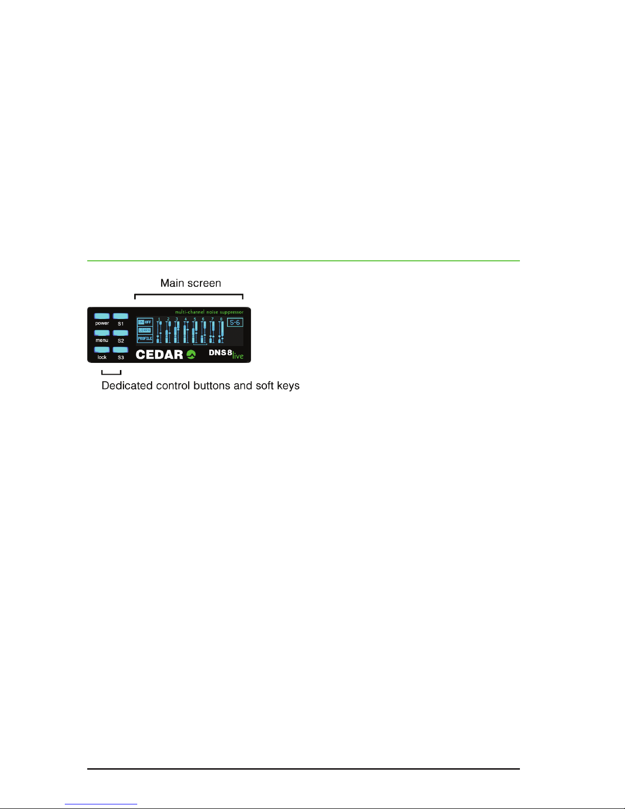
SUMMARY VIEW: SINGLE-CHANNEL TUTORIAL
Ensure that the channel you are interested in processing is the channel in focus
(clicking on its knob will do this) and that the DNS process is switched on.
You now need to set the Level and Gain parameters for this channel, which may be
accomplished automatically using the Learn function, or manually.
Setting the Level and Gain using the Learn function
There are two ways to use the Learn function:
• Identify a period when there is no wanted signal present in the audio.
Press and hold S2 (Learn) for a second or two, during which time the unit
will analyse the noise and begin to suppress it. Release S2 before the
wanted signal returns. In many cases the unit will now suppress the noise
effectively, but you can now rene Level and Gain settings if necessary.
• Press S2 and leave Learn engaged permanently. This has the advantage of
allowing the unit to track the background noise adaptively, but you cannot
modify the Level or Gain manually, nor use Detail mode when using it in this
way.
Setting the Level and Gain manually
First, you need to identify the noise level of the audio in the signal, and adjust the
Level control appropriately. Click the knob (if necessary) to highlight the righthand
fader “G” (Gain). Turn the knob anticlockwise to reduce the Gain to its minimum.
Maximum processing is now occurring, which makes it easier to determine the
noise level in that channel. Now click the encoder to highlight the “L” (Level) fader
and, starting at its lowest setting, raise this slowly. At rst, you will hear very little
happen but, at some point determined by the noise content of the signal, you will
hear the noise disappear. You should attempt to nd the lowest point at which this
occurs.
Finally you need to set an appropriate amount of noise suppression using the Gain
control. Click the knob to switch to this, and then nd the position for the Gain that
suppresses as much noise as possible without introducing unwanted artefacts into
the desired signal.

Page 11
Process On/Off
While determining the settings, you can bypass processing by pressing and
holding the channel knob (preview), or by double-clicking on the channel knob
(toggle processing on/off), or by pressing S1. Each of these methods allows you to
audition the signal before and after processing to ensure optimal results.
MULTI-CHANNEL USE
Having achieved an acceptable result for one channel, you should now proceed
to monitor each of the other channels to be processed (if any) and set these up as
above.
Groups
Grouping channels together makes them adopt identical settings, and allows
them to be adjusted together. For optimal results, the noise characteristics of all
channels of the group need to be similar. This might be the case, for example, for
groups of similar microphones located in the same environment.
Group channels by clicking two knobs simultaneously or in quick succession.
For example, pressing knobs 1 and 4 will group channels 1, 2, 3 and 4 together.
Pressing them again removes the grouping. When channels are grouped, you can
adjust their Levels and Gains using any of the grouped knobs. For example, if you
highlight the “L” fader in channel 1 and the “G” fader in channel 2 you can control
the Levels and Gains simultaneously in all four channels using just knobs 1 and 2.
The Learn function works simultaneously for all channels in a group, analysing all
of them simultaneously to nd settings that are - as much as possible - appropriate
for all of the channels within the group.
You may set up any combination of individual channels and groups provided that
the following criteria are met:
• All channels in a group must be adjacent.

Page 12
• No channel can be in two groups simultaneously.
This architecture allows you to create desirable combinations such as dual
4-channel operation, or four stereo pairs.
DETAIL VIEW
Press S3 in the default display to enter Detail view. This offers a multi-band view
of the current channel, and allows you to control each of the bands independently.
The main display shows two banks of six faders. The bands that they represent are
spaced from approximately 20Hz (leftmost) to approximately 20kHz (rightmost).
Screen and knob 7
Screen 7 displays the same overall Level and Gain information for the current
channel as was shown in the summary view, and knob 7 operates as it did in the
summary view, as follows:
Rotate: adjust the overall Level / Gain (i.e. adjust all six bands
simultaneously)
Click: toggle the focus between the Levels and the Gains
Double-click: toggle the current channel/group on/off
Press/Hold/Release: preview the current channel/group on/off
Screens and knobs 1 - 6
These allow access to the settings for the individual bands as follows:
Rotate: adjust the Level and the Gain in each of the six bands
Click: toggle the focus between the Level and the Gain
Double-click: toggle this band on/off (by setting its Gain to 0dB)
Press/Hold/Release: preview this band on/off
Multi-click: click two encoders to set the enclosed bands to the
same settings
Screen and knob 8
These allow you to step through the channels/groups.

Page 13
DETAIL VIEW: TUTORIAL
Adjusting the settings in Detail view is an extension of setting them in the summary
view described above. To do this manually for each band, you would follow the
same procedure:
• Set all the Level and Gain controls to minimum (Level= -80 and Gain= -20).
• Gradually increase the Level until the noise in that band disappears.
• Rene the Gain settings to achieve an appropriate degree of noise
suppression without artefacts.
However, it is unlikely that you will have to do this because you will be starting from
the (approximately) correct settings derived using the summary view, or obtained
from the Learn function. In either case, it should only be necessary to rene the
settings.
Note: You can also operate the Learn function in Detail view, whereupon you will
see it adjusting the settings in real time.
Pressing and holding any of knobs 1 - 6 temporarily switches that band off,
allowing you to hear the effects of noise suppression in that band alone.
Example
You may nd that, for a given piece of audio, the greatest effect comes from bands
3 and 4. This suggests that the noise is concentrated in the mid frequencies, so
higher level settings and lower gain settings are appropriate for bands 3 and 4,
whereas the gains of bands 1, 2, 5 and 6 should remain relatively close to 0dB to
ensure that minimal signal damage occurs in the bands that do not contain much
noise.
The nal conguration may look like this:

Page 14
MENUS
Select the menus by pressing the menu button. Select the desired submenu by
pressing the S1, S2 and S3 buttons. When appropriate, press the menu button to
return to the previous screen.
The menu map is as follows:
Edit
Apply
Cancel
Status
Audio
Setup
Status
information
Presets
Network
Recall
Edit Save
Prev
Up
Next
Down
Options
Edit
Erase
Clr
Apply
Cncl Del
Edit
Apply
Cancel
Edit
Apply
Cancel

Page 15
MOVING AND EDITING WITHIN MENUS
Some menus provide options to move around on screen and to edit characters or
values in specic locations.
Moving is accomplished using knob 1 when it shows the following in its associated
screen:
Editing is accomplished using knob 2 when it shows the following in its associated
screen:
STATUS
The status page reports the current audio and network status of the DNS 8 Live.
No editing is possible on this page.
In the example above, 44.1kHz audio is being received on channels 1 and 2 of
the XLR inputs, but no audio is being received on channels 3 to 8. No AES11 sync
signal has been detected at the BNC input.
The page is also reporting the unit’s MAC and IP addresses.
Note: IftheInputeldshows‘!BYP!’thenthefail-safebypasshasbeentriggered
andtheunitmustbepower-cycledtoclearit.

Page 16
PRESETS
The DNS 8 Live contains 100 memory locations (“presets”) numbered 00 to 99.
Each memory stores the process settings of all eight channels, including grouping
when appropriate. Memories do not store information such as the I/O selection.
Press the menu button followed by S2 (Presets) to enter the preset manager.
Note: The eight channel displays will continue to show the Summary or Detail
views (as appropriate) so you can continue to control the DNS 8 Live while
saving and recalling presets.
The Preset manager screen
The three possible actions on each of the softkeys perform the following functions:
S1 (Recall / Edit / Save)
Click: recall the selected preset
Press/Hold/Release: invoke the edit screen to edit the preset name or to
delete the preset
Double-click: save the current process state to the selected preset
S2 (Prev / Up)
Click: select previous preset
Press/hold/release: scroll up the preset list
Double-click: no action
S3 (Next / Down)
Click: select next preset
Press/hold/release scroll down the preset list
Double-click no action
Note: InPresetmode,theeightknobsandtheirassociatedscreenscontinue
to edit and display the appropriate (Summary or Detail) processing
parameters, allowing you to continue controlling the DNS 8 Live.

Page 17
The Edit screen
When edit screen is selected, the channel 1 and 2 knobs allow you to edit the
name of the current preset in the usual fashion.
S1 (Edit)
Click: no action
Press/Hold/Release: no action
Double-click: no action
S2 (Erase / Clr)
Click: erase the character under the cursor or to the left of the
cursor if it is positioned at the end of the name
Press/hold/release: no action
Double-click: clear the entire name
S3 (Apply / Cncl / Del)
Click: apply changes
Press/hold/release: cancel changes
Double-click: delete the preset
Note: Itisnotpossibletostoreapresetwithnoname.Ifthenameeldisempty,
the Apply option will change to Delete and will delete the preset.

Page 18
SETUP
Press S3 Setup in the default or detail screens to access the three setup options.
Click on S1, S2 or S3 to enter the Audio, Options and Network screens
respectively. Having done so, all three pages offer the same edit options:
S1 (Edit)
Click: edit the elds (see below)
S2 (Apply)
Click: apply the changes
S3 (Cancel)
Click: cancel the changes
The Audio screen
Lock
The lock eld reports which channels are locked to a valid source. In the example
above, channels 1 and 2 are receiving valid data; channels 3 to 8 are not.
Rate
The sample rate is derived from the lowest numbered channel that is receiving a
valid signal unless AES11 wordclock is being accepted at the BNC input, in which
case the sample rate will be derived from that.
Note: Thedigitalaudiosignalsfeedingtheunitmustbeatthesamesamplerate
and synchronous or loud noise may result from the consequent data errors.

Page 19
Audio and wordclock sources
Select the desired audio and wordclock sources.
Input
XLR3: audio is accepted from the XLR inputs
DB25: audio is accepted from the DB25 input
Sync
Input: wordclock is derived from the lowest numbered input
channel that has lock
BNC: AES11 wordclock is used if detected at the BNC input,
otherwise the display will report WCLK and assume that
standard wordclock is being received.
The Options screen
Click time: Determines the desired window for a double-click in the
range 160ms - 640ms
You may test the response using knob 8, which will
report whether it interprets your presses as a click, a
click/hold or a double-click
Brightness: Determines the brightness for the buttons and the
screens, which may be set independently
Boot option: Determines the settings loaded when you restart the unit:
Load defaults
Loads the factory settings
Restore last
Loads the settings in use when you last switched off the
unit
Load preset 00
Loads the settings stored in preset 00, thus allowing you
to create your own default settings

Page 20
The Network screen
Username and password
Use this window to set the username and password that will be requested by web
browsers to enable remote control of the unit. (See next page.) The defaults are:
Username: DNS8live
Password: <none>
The username and password are case-sensitive.
IP settings
Use these elds to select the desired IP settings. (Most networks have a DHCP
server that will automatically congure the DNS 8 Live to work on the network, so it
is unlikely that you will need to adjust anything on this page when DHCP is On.)
DHCP
On Dynamic Host Conguration Protocol automatically sets
up the unit to work on your local network. No manual
changes to the addresses are possible in this mode
Off congure the unit address, netmask and gateway
manually
Address: Set the unit’s address manually
Netmask: Set the netmask manually
Gateway: Set the gateway address manually
Note for network administrators
The DNS 8 Live sends its serial number as its host name in DHCP requests. If your
DHCP server registers host names in the domain name server, you can access
your DNS 8 Live as dns-8-xxxxx.yourdomain.com instead of directly by its
numeric IP address.
When congured correctly, the DNS 8 Live will respond to ICMP echo requests
(pings).
Table of contents
Other Cedar Recording Equipment manuals