Cedar CD-100M User manual

OPERATION MANUAL
TORQUE TESTER
MODEL CD-100M/10M
1571

1
Thank you very much for purchasing a TORQUE TESTER CD-100M / 10M
For safe and efficient operation, read this Operation Manual through before use, get a good understanding of the
operating precautions, capabilities of this product, how to use it, and other details, and use it correctly.
Contents
1 Safety Precautions.................................................................................................................................... 2
2Specification .............................................................................................................................................. 3
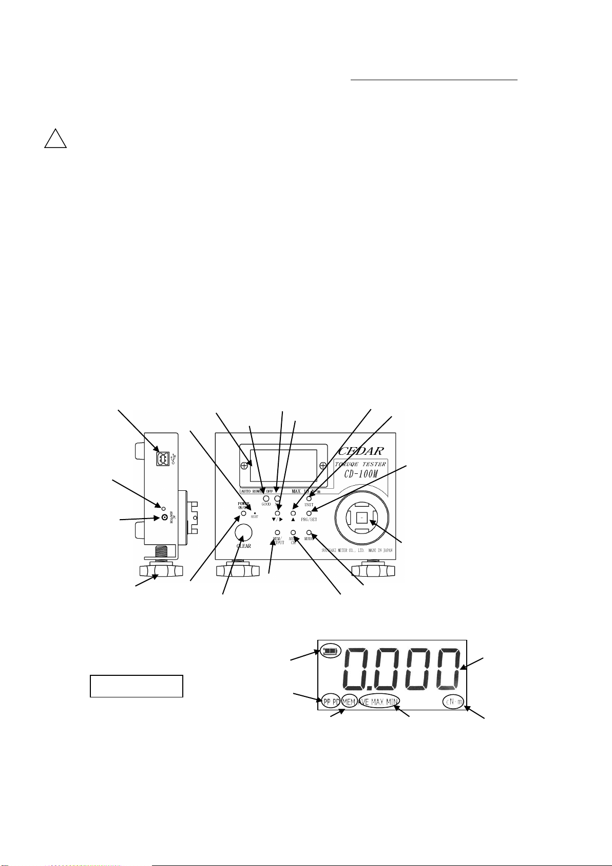
2.1 The name of each part, and the main uses .............................................................................................. 3
2.2 Specification........................................................................................................................................ 5
2.3 Outside dimension ............................................................................................................................... 5
3Preparation of Measurement...................................................................................................................... 6
3.1 Measurement Mode............................................................................................................................... 6
3.1.1 Kind in Measurement Mode............................................................................................................. 6
3.1.2 A setup and change in measurement mode ........................................................................................ 6
3.1.3 Setup and Change of Measurement Unit ......................................................................................... 6
3.2 Selection of Joint for Measurement ........................................................................................................ 7
3.2.1 SJ Joint .......................................................................................................................................... 7
3.3 Cautions at Time of Installation.............................................................................................................. 8
3.4 Power Source...................................................................................................................................... 8
3.5 About zero adjustment........................................................................................................................... 8
4Measuring Method..................................................................................................................................... 9
4.1 Measurement of Electric Driver ............................................................................................................. 9
4.1.1 Check of Torque, and Selection of Measurement Joint ....................................................................... 9
4.1.2 The method of measurement .......................................................................................................... 9
4.2 Measurement of Torque Driver Torque Wrench ..................................................................................... 10
4.2.1 Measurement of a torque driver...................................................................................................... 10
4.2.2 Measurement of Torque Wrench................................................................................................... 10
5About a convenient function .................................................................................................................... 11
5.1 Kind of Convenient Function............................................................................................................... 11
5.2 The setting method of a convenient functional numerical value .............................................................. 11
5.3 How to Use Convenient Function......................................................................................................... 13
5.3.1 Yes-no Decision............................................................................................................................ 13
5.3.2 Maximum, Minimum, and Average ................................................................................................ 14
5.3.3 It is Automatic in Display and Clear............................................................................................... 14
5.4 Real-time data output........................................................................................................................... 14
6Preservation, Display, and Output of Data............................................................................................... 14
6.1 Measurement Data .............................................................................................................................. 15
6.1.1 Preservation of Measurement Data................................................................................................. 15
6.1.2 Display and Elimination of Saved Measurement Data...................................................................... 15
6.1.3 Output of Saved Measurement Data ............................................................................................... 16
6.2 Output data......................................................................................................................................... 16
6.3 All Elimination of Saved Data.............................................................................................................. 17
6.4 Change of Output Speed of Data.......................................................................................................... 17
7System Reset............................................................................................................................................ 18
8Calibration Trust Service......................................................................................................................... 18
8.1 Periodical calibration ........................................................................................................................ 18
8.2 Guarantee.......................................................................................................................................... 18
8.3 When Troubled.................................................................................................................................. 19

2
!
1 Safety Precautions
Meanings of the "a symbol and a signal terms"
Meanings of the "a symbol and a signal terms" indicated at the top of each precaution.
Note that even an item described in Caution may lead to a serious result depending on the case.
Be sure to observe all precautions, because every one of them describes something important.
Warnings; A precaution about the possibility that mishandling may result in death or serious injury of the user.
Cautions; A precaution about the possibility that mishandling may result in personal injury or property damage.
Warnings
1. Do not apply the torque more than permission load.
If the torque more than permission load is applied, a detector will be damaged
and it will become the accident and the cause of an injury.
2. Keep a work place always clean. The untidy place and a work stand cause the accident.
3. Situation of work place.
- Avoid use in the place where high temperature, high humidity, and direct rays hit,
and the place with much garbage and dust.
- Temperature uses it in the place of regularity (about 20 degrees).
- Make a work place bright enough.
- Do not use or charge in the place with an inflammable liquid or gas.
4. Do not bring a child close. Do not bring close to a work place except a worker.
5. Do not handle code violently. Do not move the product while holding its cord
when it is attached to the product. Do not pull the cord to unplug it.
6. Services carefully.
- In order to work with sufficient efficiency safely, the product, a bit / socket, etc. are checked periodically.
- Exchange of accessories follows the operation manual.
- Check a code periodically, and when having damaged, exchange them.
7. In the following case, turn off switch of the product, and pull out plug from power supply.
- When not using or charging.
- When fixing.
- When danger can be expected in addition to this.
8. Check whether there is not any damaged portion.
- Check whether there is not any damage before use enough
and it checks whether it operates normally or a predetermined function is demonstrated.
- Check whether there are not any abnormalities in all the parts that do influence in case of use.
- Perform parts exchange according to the operation manual.
9. Use Accessories, appointed proper bit and socket.
Do not use it except the accessories, the proper bit or the socket which are indicated by the operation manual.
10. Request repair from store.
- Do not convert.
- Repair is surely an order to the store of a purchase.
If it fixes without the knowledge of repair, or technology, sufficient performance will not be demonstrated
and it will become the accident and the cause of an injury.
11. Do not decompose or do not give a strong shock and a strong vibration.
Since this product is precision apparatus, do not decompose.
By a superfluous shock or a vibration, when a detection machine and a display part breaks down,
sufficient performance is not demonstrated and it will become the accident and the cause of an injury.
12. Charge Correctly.
- Carry out on the displayed voltage in the case of charge. Do not use a DC power supply or engine generator.
It generates heat unusually and becomes the cause of a fire.
- Perform charge in a well ventilated place. Do not cover with cloth etc. during charge.
13. It is cautious of electric shock.
The wet hand should not describe a power-supply plug. There is fear of an electric shock.
14. Abattery (contained in the product) is not thrown into fire.
There is a burst or a possibility that a detrimental substance may come out.
15. The nickel-cadmium battery or the nickel-hydrogen battery is being used for the product of our company.
It is recycling resources. Leave exchange to our company.

3
!
16. Connect after turning off power supply of all apparatus, when connecting with external apparatus.
There is fear of an electric shock or apparatus damage.
17. When situations other than contents of the operation manual occur, stop use immediately, and it is inquiry.
18. When not using a main part six months or more for quality maintenance of a battery, you have to charge once in
half a year.(There is a case where it becomes impossible to use a battery)
Cautions
1.When not using the product, keep it exactly.
(In the dry place, the high place which a child's hand does not reach or the place which a key requires)
When you convey, use the packing box containing the product.
2. Orderly dress performs. (Since there is a possibility that it may be involved in a rotation part,
neither loose clothes nor accessories, such as a necklace, are worn.)
3. It does not work with an impossible posture. (Always brace a step and maintain balance.)
4. Work, being careful enough without being inattentive.
*When using the product, it carries out by being careful enough of the method of dealing with it,
the method of work, a surrounding situation, etc.
*It is not used when it is tired.
*within the limits of common sense
(Since it has written that it is common in all of products of our company,
there is a portion which does not suit with some product.)
2Specification
The main functions and uses of this circuit tester are explained.
2.1 The name of each part, and the main uses
①Data output terminal
②Pilot Lamp During Charge
③AC/DC
Adaptor Terminal
④Fixed Knob
⑦ON/OFF
(Power) Key
⑧CLEAR Key
⑥System Reset
⑨Memory Display /
Data Output Key
⑩Average Display
⑪Measurement Mode Key
⑫Torque Detecting Element
⑯DOWN/MOVE
key
⑬Numerical Setting Mode /
Determination Key
⑭Measurement Unit Key
⑱GOOD lamp
⑰NG Lamp
A Battery residual quantity
B Measurement mode
D The maximum, the
minimum, and an average
E Measurement unit
F Torque value
Display section
C Memory data
⑮UP Key
⑤Display Board

4
The name of each part
The main use and contents
①Data output terminal
The serial output of the measurement data is carried out. USB form (B type).
②Pilot Lamp During Charge
The light is switched on during charge.
TheAC/DC adaptor of exclusive use is used for charge.
③AC/DC Adaptor Terminal
The plug of anAC/DC adaptor is inserted.
④Fixed Knob
At the time of measurement, a fixed thing etc. is put and a main part is fixed.
⑤Display Board
A torque value and various information are displayed.
⑥System Reset
The time of full electric discharge etc. is used when resetting a system.
⑦ON/OFF (Power) Key
It use it in ON/OFF of the power supply.
⑧CLEAR (Clear) Key
It pushes, when measurement is completed, and giving an indication zero.
When the memory data is deleted, it uses it.
It is used at the time of zero adjustment.
⑨Memory Display
/ Data Output Key
It is used when displaying the memory data saved on the main part.
It uses, when outputting the saved data.
⑩Average Display Key
It is used when displaying the maximum, the minimum,
and the average of measured value.
⑪Measurement Mode Key
It is used when changing measurement mode.
It is used for the check of the function set up
during a functional numerical value setup.
⑫Torque Detecting Element
Torque is measured in this portion. The joint for measurement is attached,
or the angle of a tool is inserted, and it measure.
⑬Numerical Setting Mode
/ Determination Key
It is used when changing the setting numerical value of various functions.
It is used when determining a numerical value.
⑭Measurement Unit Key
It is used when changing the unit of measurement.
⑮▲Key
(UP Key)
It is used when making a numerical value increase at the time
of a functional numerical value setup.
The memory data to choose are changed (increase).
⑯▼/▶Key
( DOWN・MOVE Key)
At the time of a numerical setup, when decreasing a numerical value, it is used.
It is used when moving the place which changes a numerical value to the right.
The memory data to choose are changed (decrease).
⑰NG Lamp
It blinks, when the yes-no decision is set up, and it is "no."
Light is carried out at the time of exaggerated torque.
⑱GOOD Lamp
The light is switched on when the yes-no decision is set up, and it is "yes"
The light is switched on when each functional numerical value is under setup.
Display section
A Battery residual quantity
The residual quantity of an internal charge of battery is displayed.
B Measurement mode
A chosen measurement mode is displayed.
C Memory data
When a memory data is used, it displays.
D The maximum,
the minimum, and an average
When a maximum, the minimum, and the average value is used, it displays.
E Measurement unit
The measurement unit chosen now is displayed.
F Torque value
The torque value in each measurement mode and unit is displayed.

5
2.2 Specification
Model name
CD-100M
CD-10M
Measuring range
0.10~10 N・m
0.010~1N・m
1.0~100 kgf・cm
0.10~10 kgf・cm
1.0~90 lbf・in
0.10~9lbf・in
Accuracy
±0.5%(199 or less digit±1digit)
Display
The 3.5 figures digital display of LCD
The measurement direction
CW-CCW (right and left)
Measurement Mode
P-P (peak to peak) /T-R (track) /P-D (peak-down) /
C (Real-time Output)
High and low limits judging
function
High and low value is measurement within the limits, and can be set up.
The setting numerical value of five sets is saved.
Results judgment
It can perform results judgment within the setting.(in P-P mode)
It confirms with lamp lighting or a buzzer.
The Maximum, the minimum,
and the average value display
It displays the maximum, the minimum, average value,
(As opposed to a maximum of 800 data)
Real-time Output
Load torque value is outputted every about1/ 180 second.
(Achange whole 1 / 12 seconds is possible)
Data memory
Measured value - 800 data
Data output
ASCII format (baud rate 19200)
Automatic clear time
In 0.1 - 3.0 seconds (0.5 seconds interval) an indication is automatically given zero.
It is a manual zero clearance by 0.0 second setup.
One-touch zero
By pushing a clear button, zero adjustment can be performed by one-touch.
Battery
Ni-cd battery 1.2V×5sells (700mAh) /300 times or more charge life
Auto power OFF
Power-supply OFF is carried out after the neglect during 10 minutes.
Charge time / use time
About 3 hours / About 12 hours use consecutive at full charge time
Socket size
□20mm / □9.5mm
Accessories
(One piece each)
Measurement joint SJ-50、SJ-10K
Measurement joint SJ-10
(4 bits HEX opposite side 6mm)
(4 bits HEX opposite side 5mm)
An AC/DC adaptor
Exclusive case
Result of calibration , Certification on calibration , Traceability system figure
* Do not use it for measurement of an impact tool
*Measurement while charging cannot be performed. A plug is pulled out at the time of measurement.
2.3 Outside dimension

6
3Preparation of Measurement
It prepares and checks, before starting measurement
3.1 Measurement Mode
About the measurement mode which can be measured from this model (measuring method)
3.1.1 Kind in Measurement Mode
Measurement mode
Display
Contents
P-P
(peak to peak)
Display section「PP」
The maximum under measurement is always displayed.
Load holds more than from 20digits*.
Usually, this mode is used.
P-D
(peak-down)
Display section「PD」
A value when a load torque value changes
from a rise to descent is displayed. It carries out,
once it pushes a clear button, when applying re-load.
Load operates more than from 20digits*.
It is suitable for measurement of a torque wrench etc.
C
(Real-time Output)
Display section「C」
The data output of the load torque value is carried out
every about 1 / 180 seconds.
(Achange whole 1 / 12 seconds is possible)
It is suitable for torque curve creation
or a screw bundle examination.
T-R
(track)
There is no display
It is mainly used at the time of calibration etc.
The value of the load torque concerning
a detector is displayed as it is.
(There is no display.)
* digit -- CD-100M - 10digit is 0.10 N・m(1.0kgf-cm/1.0lbf-in)
CD-10M - 10digit is 0.010 N・m(0.10kgf-cm/0.10lbf-in)
3.1.2 A setup and change in measurement mode
Button to be used -- "MODE"
Pushing the "MODE" button is continued for about 1 second.
(It is a setting mode pushed long
so that the measurement should not change while measuring it. )
The measurement mode display changes.
The measurement mode to be used is chosen.
The display changes sequentially if it keeps pushing.
Truck (with no display) -> Peak hold (PP) -> peak down( PD) -> Real-time output (C) -> Truck
3.1.3 Setup and Change of Measurement Unit
Button to be used -- "UNIT"
Pushing the "UNIT" button is continued for about 1 second.
(It is a setting mode pushed long
so that the measurement should not change while measuring it.)
The measurement unit display changes.
A push on a button changes a display.
The measurement unit to be used is chosen.
The display changes sequentially if it keeps pushing.

7
3.2 Selection of Joint for Measurement
Some "joint for measurement" is attached to this product.
At the time of measurement of a tool, the joint corresponding to a tool is surely used.
3.2.1 SJ Joint
SJ joint is used for measurement of an electric driver.
In case joint is chosen, tolerance level is checked and it is cautious of exaggerated torque enough.
SJ joint (coiled-spring compression system))
SJ50 (MAX 5N・m)SJ10K(MAX 1N・m) It attaches to CD100. Cap bolt portion H6
SJ10 (MAX 1N・m) It attaches to CD10. Cap bolt portion H5
The bolt omission prevention function was newly
carried in joint. By attaching an omission
prevention screw, if a bolt separates from a plinth, it
will race, and it does not decompose and trouble is
not caused to work. (However, when it continues
racing, a ridge may be worn out and torque value
may change.)Moreover, by wear, the metal fatigue,
etc. of a screw, where a spring is closed, it is left,
and a bolt may jump out with the pressure.
New joint which served also as the measure against dangerous prevention in that case. (PAT,P)
The cautions on use
The load more than the measurement range is not applied by any means.
It checks before use whether grease is attached to bolt and bearing.
After use is kept where a spring is surely loosened.
The number of times of an exchange standard is about 2500 times.
When the following condition comes out, use is stopped and new joint is used.
When there is wear of a bend and a ridge
When there is sound etc.

8
3.3 Cautions at Time of Installation
At the time of measurement, it installs so that a circuit tester main part may not move.
When especially high torque starts, A fixed knob is used.
3.4 Power Source
This model is using the "Ni-cd charge battery." Charge it with an AC/DC exclusive adaptor.
The display of battery residual quantity is displayed on the display upper part.
The meaning of a display
Display
Contents
There is battery residual quantity.
Battery residual quantity has decreased. It charges soon.
When using many lamps, such as a yes-no decision, and buzzers,
it charges a little early.
There is almost no battery residual quantity. It charges urgently.
When there is no battery residual quantity, a power source is shut off immediately.
Charge uses an AC-DC exclusive adaptor by all means.
If key operation is not performed for 10 minutes, a power source will be in an OFF state automatically.
When you turn off the power, push an ON/OFF button lightly for about 1 second.
* If anAC/DC adaptor is connected, a display may be a full display,
but while the pilot lamp is on, continue charge.
3.5 About zero adjustment
At the following, this tester is performed zero adjustment automatically.
1.When power is switched on 2.When measurement mode is changed
(When torque started during this movement,
it becomes impossible for 0 points to shift, and to do a normal measurement.
At the time of power supply injection and the measurement changing,
confirm that torque does not started.)
Moreover, zero points might shift when zero points do not return.
In that case, zero points adjustments by the following methods.
1. Check that torque has not started a detecting element.
2. If CLEAR is kept pushed, Red LED will switch on the light.
If the light is switched on, the CLEAR button will be detached promptly.
3. Red LED will disappear, display will be zero, zero adjustment is completed.
*When continue pushing it in a state with the red LED, display it with
and become all elimination of memory data. (Leave Red LED unattended. It will be zero.)

9
4Measuring Method
The concrete measuring method of various tools is explained.
4.1 Measurement of Electric Driver
The torque of the electric driver whose set torque is possible of operation is measured.
In the case of the electric driver which performs impact operation, it may be unable to measure normally.
4.1.1 Check of Torque, and Selection of Measurement Joint
The standard of the output torque of the electric driver to measure is checked, and it checks whether it is in the
measuring range of a tester. Especially when you use "CD-10M", be careful. * CD-10M are a maximum of 1
N-m=10kgf・cm.
Next, SJ joint to be used is chosen. First, it checks whether the torque of the standard of an electric driver is
in the tolerance level of SJ joint. Next, the bit of an electric driver and the screw of SJ joint head to measure
confirm whether it gears exactly. When a bit does not suit a screw well, it becomes the cause of coming-out or
screw-head breakage. In this case, a bit is exchanged for other things, or the kind of screw is changed and it
corresponds. Moreover, if it exchanges for the attached bit for measurement, it is also possible to remove the
screw of the head of SJ joint, and to measure as it is.
4.1.2 The method of measurement
1. Install SJ joint in a torque detecting element.
(SJ joint is fixable using the tapped hole for fixation of a
detecting-element nail portion.)
2. Press a power-source key and switch on a power. (A power source
is switched on after checking that load is not applied to a detecting
element, since zero adjustment is performed at this time)
3. Check whether measurement mode is "PP" peak interrupt mode.
Measurement mode is changed into "PP" when "PP" is not displayed on display (3.1.2 references).
4. The fit of the bit of an electric driver is carried out to the screw of SJ joint head,
operate an electric driver, fasten, and perform lump operation. It checks whether the
spring of SJ joint is loosening at this time. When you are not loosening, please be
sure to start measurement after loosening.
※Before operation, a display checks in "0." When it is not "0", a clear button is
pushed and it is made "0."
5. If it binds tight and operation finishes, the torque value of a display board will be
checked.
6. Loosen the spring of SJ joint using inversion operation of a driver.
7. If the "CLEAR" button is pushed, it will be in the state where a display is cleared and measurement is possible
again.

10
4.2 Measurement of Torque Driver Torque Wrench
Torque of operation, such as a manual torque driver and a torque wrench, is measured.
4.2.1 Measurement of a torque driver
1. Check whether measurement mode is "PP" peak interrupt mode.
Measurement mode is changed into "PP" when "PP" is not
displayed on display (3.1.2 references).
2. The bit of a torque driver is replaced with a commercial bit adapter
(the drive section is the thing of □9.5), and is inserted in □9.5 portion
of a detecting-element inner side.
3. Operate by binding tight, and bind tight until it races.
※Before operation, a display checks in "0." When it is not "0", a
clear button is pushed and it is made "0."
4. If it races, the torque value of a display board will be checked.
5. If the "CLEAR" button is pushed, it will be in the state where a display is cleared and measurement is
possible again.
4.2.2 Measurement of Torque Wrench
Although measurement of a torque wrench is also possible, it restricts to the thing which is in measuring range
and operates.
1. Check whether measurement mode is "PD" peak down mode.
Measurement mode is changed into "PD" when "PD" is not displayed
on display (3.1.2 references).
2. Since □9.5 Hole is Open inside Torque Detecting Element, Insert
Angle Drive of Wrench in the Portion.
3. Operate by binding tight.
※Before operation, a display checks in "0." When it is not "0", a
clear button is pushed and it is made "0."
4. By click operation, if a torque value falls temporarily, the value will be displayed and green (GOOD) will
light up. For the stable measurement, a "peak down start value" is set up beforehand. (5.2 references)
5. If the "CLEAR" button is pushed, it will be in the state where a display is cleared and measurement is
possible again.
* When it cannot insert in □9.5 hole directly, use a conversion adapter etc.

11
5About a convenient function
This model carries various functions convenient to measure.
You can use the function appropriate for each management condition more efficiently because you use.
5.1 Kind of Convenient Function
1. The yes-no decision which sets up a maximum value and a minimum value.
The maximum value and minimum value of measured value can be set up respectively.
It is a success judging (Green GOOD lamp lighting) within the limits of an upper minimum value.
A failure judging (Red NG lamp blink) is carried out of the range.
2. The value which starts the measurement at the time of peak-down mode can be set up.
When measuring a torque driver/wrench etc., the unrelated torque change
at the time of a measurement start can be disregarded.
3. The value which starts the output at the time of real-time output mode can be set up.
4. Time to be automatic and clear the display of a measurement result can be set up.
5. How to sound buzzer sound can be chosen.
5.2 The setting method of a convenient functional numerical value
The numerical value for using a convenient function is set up.
PRG/SET, and▲and▼/▶are used.
1. Change in Setting Mode, and Setup of Channel
If it continues pressing the PRG/SET key for about 1 second, green
LED (GOOD lamp) will stick, the channel set up now is displayed.
The channel which wants to change a channel or the contents to use
is set up by the UP key or the DOWN key. (ch1-ch4)
When you change the channel to be used, press the "CLR" key after
change. When changing the contents of a setting of a channel, the
PRG key is pressed again. * After-mentioned and
cannot do a setup for every channel.
2. Setup of Maximum Value
A maximum value is displayed after displaying will arrive.
The maximum value is set up by UP and DOWN key.
Since the fourth figure will blink if DOWN key is pressed first,
a numerical value is chosen by UP key.
If a setup of a numerical value of the fourth figure finishes,
DOWN key will be pressed again. Since the treble figures blink,
a numerical value is set up similarly.
▲A numerical value is increased.
▼/▶A place is changed.
PRG/SET A numerical value
is determined.
The fourth figure blinks by
1.
PushUP
Push DOWN
The treble figures blink.
When a maximum value is set as 1.250
Push DOWN
The fourth figure blinks.
Pushing for about 1
second, it is green
LED lighting

12
The second figures and the first figure are set up similarly.
It is a numerical increase at UP key. One figure falls by DOWN key.
If DOWN is pushed again after setting up the first figure,
since all figures will be displayed, check the set point.
When the setting is corrected, it sets it from the fourth digit again
pushing DOWN key. If a setup of a maximum value is completed,
the PRG key will be pressed again.
* When the PRG key is pressed while setting up, move to the next setting.
3. Setup of Minimum Value
A minimum value is displayed after displaying
The minimum value of torque measurement is set up by the ▲key
and the ▼/▶key like a maximum value.
The a minimum value cannot set a value bigger than
a maximum limit value.
If a setup is completed, the PRG/SET key will be pressed again.
4. Setup of Peak Down Start Value
After displaying , a peak down start value is displayed.
A peak down start value is set up by ▲key and ▼/▶key like a
maximum value.
(When it fell 15 digits ahead of this value, peak-down displays it)
If a setup is completed, the PRG/SET key will be pressed again.
5. Setup of Real-time Output Start Value
After displaying , a real-time output start value is displayed.
A value is set up similarly.
When this value is set to 0, the inside of real-time output mode
continues outputting data.
If a setup is completed, the PRG/SET key will be pressed again.
6. Auto Clear Setup
After displaying , a time of an auto clearance is displayed.
Time to carry out the zero clearance of the display is set up by ▲or
▼/▶. (A setup the whole 0.5 is possible in 0.1 - 3.0 seconds) It
increases by ▲. It decreases by ▼/▶.Setup-time selection
0.0C⇔0.1C⇔0.5C⇔1.0C⇔1.5C⇔2.0C⇔2.5C⇔3.0C⇔0.0C
If it sets up by 0.0C, it will become the zero clearance in manual
operation.
When a minimum value is set as 0.500
The third figure blinks by 5
Push▲5 times
Push ▼/▶2 times
The third figure blinks
When a peak down start value is set as 0.300
The third figure blinks by 3
Push▲3times
Push▼/▶2 times
The third figure blinks
Push PRG/SET
Push PRG/SET
When a real-time output start value is set as 0.010
Push▼/▶3 times
The double figures blink
Push▲8 times
The double figures blink by "1"
Push PRG/SET
When auto clear time is set as 1
second
Push ▲twice
Push PRG/SET
Push UP twice
The treble figures blink by "2.
Push DOWN
The second figures blink.
Push PRG
The second figures blink by "5."
PushUP 5 times

13
* When set up except 0.0C, a zero clearance is not carried out
even if it pushes a Clear key.
If a setup is completed, the PRG/SET key will be pressed again.
7.Setup of Buzzer
After displaying , an ON-OFF-FF setup of a buzzer is
displayed. How to sound a buzzer is set up by ▲and ▼/▶.
( :Sound altogether :Don't sound except exaggerated
torque. :Only NG sounds.)
If a setup is completed, the PRG/SET key will be pressed again.
8. End of Setup
It is displayed and is a setting end. Green LED disappears.
(The inside of setting mode has turned on green LED )
* When ending a setup on the way, press the CLEAR key. It is
displayed as and will be in the state where it can measure.
Green LED puts out the light.
* What value or when the numerical value set up now checks, it
presses the MODE key. The item of the numerical value set as a
display board now is displayed.( 、 、 、 、
、)
5.3 How to Use Convenient Function
I introduce the method of the measurement using a convenient function.
5.3.1 Yes-no Decision
A measurement result judges the inside of a fiducially point, or the outside of a fiducially point, and tells you
about at a lamp or a buzzer.
.1. Set up the "maximum value" and the "minimum value" used as a standard. (Reference 5.2)
2. Measurement mode checks in "PP."(Only measurement mode "PP" of a yes-no decision is effective)
3. When measured value is between a minimum and a maximum , a GOOD lamp lights up.
When measured value is not between a minimum and a maximum, NG lamp blinks and a buzzer sounds.
4. If measurement is completed, the CLEAR key will be pressed and an indication will be given zero.
At this time, the lamp and buzzer of a yes-no decision disappear.
A yes-no decision is performed only when measurement mode is "P-P."(10 or more digits)
Detection of the value of a peak-down switches on a Green (GOOD) lamp at the time of P-D mode.
Below minimum *
Within the limits
Beyond a maximum
Exaggerated torque
Lamp
Red blink (slowly)
Green lighting
Red blink (quick)
Red lighting
Buzzer
Intermittence sound (slowly)
Continuation sound
Intermittence sound (quick)
Continuation sound
Below minimum value * While the load under measurement has not reached a minimum value, it judges, when
load is almost lost (less than 20 digits). (It does not judge, when maximum does not reach 20digit(s))
The item under setup is checked.
When setting up for sounding a buzzer
Push PRG/SET

14
5.3.2 Maximum, Minimum, and Average
The maximum, the minimum value, and the average value of the measurements data saved can be displayed
and checked. However, it becomes calculation of only the data (data of the same measurement direction) of the
same mark as a memory number "001" (the first data).
When data 001 is + (the CW direction), only + (the CW direction) is.
- (The CCW direction) Only for - (the CCW direction), a case is.
(1) STATA key is pressed.
(2) As Opposed to Data Measured and Saved
1) The number of data -- With no display
2)Maximum Torque value -- "MAX" Display
3)Minimum Torque value -- "MIN" Display
4)Average Torque value -- "AVE" Display
5.3.3 It is Automatic in Display and Clear
When carrying out repeat measurement, even if it does not push the clear button after a measurement end, a
display can be cleared automatically.
1. Set up the "auto clear time" of a convenient functional numerical value.(5.2 Refer)
2. After a measurement end, if the time set up after the load concerning a detecting element was lost passes, a
display will be cleared.
* When auto clear time is set up, a display is not cleared even if it presses the "CLEAR key."
5.4 Real-time data output
A data output (real-time output mode) can be carried out about 180 times in 1 second.
It can switch every 1/ 12 seconds. The change method 「6.5 Change of Output Speed of Data」Reference
1)Set measurement mode as "real-time output" mode.( Reference 3.1.2)
2)If torque load becomes beyond the value set up beforehand,
the data output of the load torque will be carried out.
3)If torque load becomes under , a data output will stop.
* During a real-time data output, since the torque display changes at high speed,
it stops being able to be visible very easily.
* When the output of data is not carried out by setup of , even if torque has started,
the torque display has become with "0."
* When is set as "0", the inside of real-time output mode continues taking out data.
The data outside the measurement range is used as a reference value.
Although the data near "0" may be fluctuated also in the time of the no-load,
it is not failure with the condition on data processing.
6Preservation, Display, and Output of Data
Preservation, a display, and an output can be carried out for data, such as measurement data and the average.
Whenever data press the CLEAR key or require an auto clearance, as soon as memory memorizes,
they output a signal also to a data output terminal.
Statistics data output a signal also to a data output terminal at the same time they display data.

15
6.1 Measurement Data
6.1.1 Preservation of Measurement Data
Memory data are always saved, whenever it presses the CLEAR key or an auto clearance starts.
When a lot of data are treated, we recommend you to eliminate data before use.
* Begin the memory of data from the data number 001. When data are already memorized,
it saves from the following memory number. Preservation of a maximum of 800 data can be performed,
and if it exceeds 800 data, it will be overwritten from No. 001. Since front data will disappear,
when exceeding 800 data, save them in a personal computer etc.
6.1.2 Display and Elimination of Saved Measurement Data
1. If the MEM/OUTPUT key is pressed, it will be displayed as
"MEM", and the data number and measured value which were saved
at the end will be displayed by turns.
2. If ▲key or ▼/▶key is pressed, a memory number is changed and
data can be searched.
If button operation is left for 6 seconds, the "MEM" display will
disappear and it will move to measurement mode.
* When memory data are eliminated individually
3. If the CLEAR key is pressed while displaying a memory number
and a torque value on alternation, it will blink .
4. If the CLEAR key is again pressed during blink, the data which
displayed as and were chosen will be eliminated.
(Subsequent data slide data to the eliminated portion)
5. If it is left during blink, it will be in the state which can
be measured. (Data are not eliminated)
* When the range is specified and memory data are eliminated
3. Press ▲key or ▼/▶key and display the data of the beginning of
data to erase.
4. If the CLEAR key is pressed while displaying a memory number
and a torque value on alternation, it will blink .
5. Since a data number will increase if ▲key is pressed,
display the data of the last of the range to erase.
⑥If the CLEAR key is pressed while displaying a memory number
and a torque value on alternation, the data of the range which
displayed as and was chosen will be eliminated. If no button
CLR Blink
Push CLEAR
PUsh CLEAR
When the data numbers 005-010 are eliminated
Push ▼/▶
Push CLEAR
CLR Blink
Push ▲
Push CLEAR
Data are eliminated
Data are eliminated

16
operations are carried out at this time, it will check whether it blinks
with and eliminates.
When eliminating, the CLEAR key is pressed during blink.
When stopping elimination, it is left as it is.
It returns to a torque display and data are not eliminated.
* When memory data are eliminated, the data saved after that slide to
the data number.
6.1.3 Output of Saved Measurement Data
1. A push on the MEM/OUTPUT key displays by turns the data
number and measured value which were saved at the end.
2. While displaying a data number and measured value, press the
MEM/OUTPUT key once again.
(It becomes data output preparation)
3. Since a data number is displayed after displaying it as
(first address), choose the data number of the first data to output by
▲or ▼/▶.
4. Since a data number is displayed after displaying it as
(last address), choose the data number of the data of the last to output
by ▲or ▼/▶.
The MEM/OUTPUT key will be pressed if selection finishes.
5.Display it as and output.
After an output finishes, it returns to a measurement state.
* Press the CLEAR key for about 1 second to stop an output during
an output.
6.2 Output data
Output data are outputted in the ASCII format with a USB cable.
In addition, in order to take in data, driver software needs to be installed separately.
About installation of driver software
Homepage http: of our company http://www.cedar.co.jp/ or
FTDI Chips Virtual COM Port Drivers http://www.ftdichip.com/Drivers/VCP.htm
It checks.
Data Format
Data bit length
start bit 1 + data bit 8 + stop bit 2 + no parity
Baud rate
19200bps
Connector form
USB(B type)
The format of data has the following two kinds.
When the data numbers 005-070 are outputted
Push MEM/OUTPUT
Push MEM/OUTPUT
Push ▲
Push MEM/OUTPUT
Push ▼/▶
Push MEM/Output
The first data number to output
The last data number to output

17
①Format at the Time of Measured Value and Statistics Data Output
18
○○○
OE
20
±
○○○○○
20
OF
○○○○○○
OD
CAN
※
SO
Space
Sign
Measured
value
Space
SI
Unit
CR
All data 21
②Data Format at the Time of Real-time Output Mode
18
±
○○○○○
OD
CAN
Sign
Measured value
CR
All data 8
The contents of data
CAN:Cancellation
※: at the time of a measured-value output
At the time of a memory data output "a data number"
At the time of the output in a clearance "a space"
: At the time of a Statistics Data output "N" The number of data, "MAX" Maximum,
"MIN" Minimum value, "m" Average value
SO :Double width expansion printing specification
±:Measurement sign + A direction with a bundle -The Return Direction
Measured value: A decimal point is also included. The last is a space when there is no decimal point.
10. 00---- 10.00
SI :Double width expansion printing release
Unit :In N-m etc., the remainder is a space.
N・m---- N・m (kgf・cm---- kgf・cm )
CR :Carriage return
△cautions An interface cable is used for connection of a computer.
prepare a cable according to a computer. Ask our company a cable.
6.3 All Elimination of Saved Data
1. When carrying out package elimination of all the data, it continues pushing until it displays the CLEAR key as
.(About 4 seconds)
* Push continuously, and after a while (about 2 seconds), although Red LED switches on the light, it continues
pushing as it is.
2. If the CLEAR key is again pressed during blink, it will be indicated by blink with .
3. If the CLEAR key is pressed again, it will be displayed as and all data will be eliminated.
(The setting numerical value of each function is not cleared)
* When operation is left during ・blink, it will be in the state which can be measured.
(Memory is not cleared)
6.4 Change of Output Speed of Data
The speed of the output at the time of outputting the data saved can be changed.
A. For Printer Output (Low Speed) -- Setup "00"

18
B. For Personal Computer Output (High Speed) -- Setup "01"
This setup is adapted also for the change of the output timing of real-time output mode.
A. Low Speed (Every about 1 / 12 Seconds) -- Setup "00"
B. High Speed (Every about 1 / 180 Seconds) -- Setup "01"
(It is set as "01" at the time of purchase.)
The change of a setup is performed by the following methods.
1. In the state of a power source OFF, pressing the PRG key, press the ON/OFF key
and switch on a power source.
2. If the PRG key is detached, it will be displayed as "01" or "00."
Since it will change if ▲key is pressed, a setup is chosen.
3. If the PRG key is pressed again, after displaying it as , it returns to a torque display,
and will be in the state which can be measured.
7System Reset
CPU in the tester might not start even if the battery charges it with
electricity complete discharged. (When not using it for a long term)
In that case, AC/DC adaptors is connected and push the system reset button. (A system reset button is beside a
power button.)
It will be in an initial state (all the contents of memory are eliminated).
Do not use it excluding the following condition.
* When the display doesn't appear even if this machine is not used for a long term and charged.
* Additionally, when the tester doesn't work.
Since all the contents of memory are eliminated when system reset is performed, redo a setup once again.
8Calibration Trust Service
8.1 Periodical calibration
Aregular proofreading is necessary to manage the accuracy of torque tester.
By our company, the proofreading with the high reliability traced to the national standard is performed,
and in order to use it within accuracy, I recommend you one proofreading per year.
(Periodical calibration is a charge.)
An inspection report, a proofreading certificate, and traceability system figure attachment
8.2 Guarantee
Although manufactured under sufficient quality control, if the fault which originates in manufacture,
transportation, etc. of our company within one year after a purchase should occur,
I will fix this machine gratuitously.
In the following case, it becomes a charge within the term of a guarantee.
Failure and damage by the error, and unjust repair and reconstruction on use
Failure and damage by the natural disaster, pollution, unusual voltage, etc.

19
8.3 When Troubled
The checkpoint when being troubled. Before judging it as failure
When functional fault arises, check based on the following table.
By the corresponding processing, when fault is not canceled, tell repair to our company or a store.
In addition, I am allowed to make a torque tester's term of a guarantee into one year from a purchase.
(However, there may be onerous in the contents of repair.)
Use a wish attached case and a plastic Case as an object for storage of a measuring instrument.
Moreover, when you convey this product to our company by check, proofreading, repair, etc.,
for product protection, put into this case and is sure to send.
For any inquiry,
Contact your dealer.
-ISO9001-
E-mail sales@cedar.co.jp
Homepage http://www.cedar.co.jp
SUGISAKI METER CO.,LTD.
condition
checkpoint
solution
Apower supply is not
turned on.
Is charge carried out?
Carry out regular time charge using
the exclusive charger attached.
Even if it turns on a
power switch, a LOBAT
lamp blinks and a power
supply is shut off
immediately.
Charge is insufficient.
Carry out regular time charge using
the exclusive charger attached.
It does not display, even
if it switches on a power
supply after charge of
regulation time.
If it is not used over a long
period of time, an internal
battery will carry out full
electric discharge.
An AC/DC adaptor is connected and a
system reset button is pushed.
After a return, push a clear button and
give an indication zero.
It cannot measure.
When torque is applied, does a
numerical value change?
The gauge may be damaged when not
changing. Request repair.
Is it the numerical value of
each function under setup?
End a setup and return to measurement
mode.
Adisplay disappears
immediately.(It does not
hold by measurement
mode PP/PD)
It is used setting up an auto
clearance.
Check the setting item of an auto clear
function again. When there is no
necessity, set it as 0.0C.
Azero point cannot be
taken.
Did you clear and make it
zero?
"3.5" is seen and zero adjustment is
performed.
By real-time output
mode, even if it imposes
torque, a display does
not change.
Data are not outputted.
Torque has not reached a
real-time output start value.
At real-time output mode, when
torque is under a "CLO" real-time
output start value, a data output does
not give an indication with "0", either.
Please change the value of "CLO" into
a suitable value.
This manual suits for next models
1
Table of contents
Other Cedar Test Equipment manuals