Boston, U.S.
100 Franklin St.,
Boston, MA 02110
Gothenburg, Sweden
Arvid Wallgrens Backe 20,
Gothenburg, 41346
Virginia, U.S.
2000 Kraft Dr., Suite 2125
Blacksburg, VA 24060
46-29 Yoshida-Shimo Adachi-
cho, Sakyo-ku, Kyoto
www.cellink.com | +1 (833) CELLINK
Installation of BIO X Autocalibration Kit
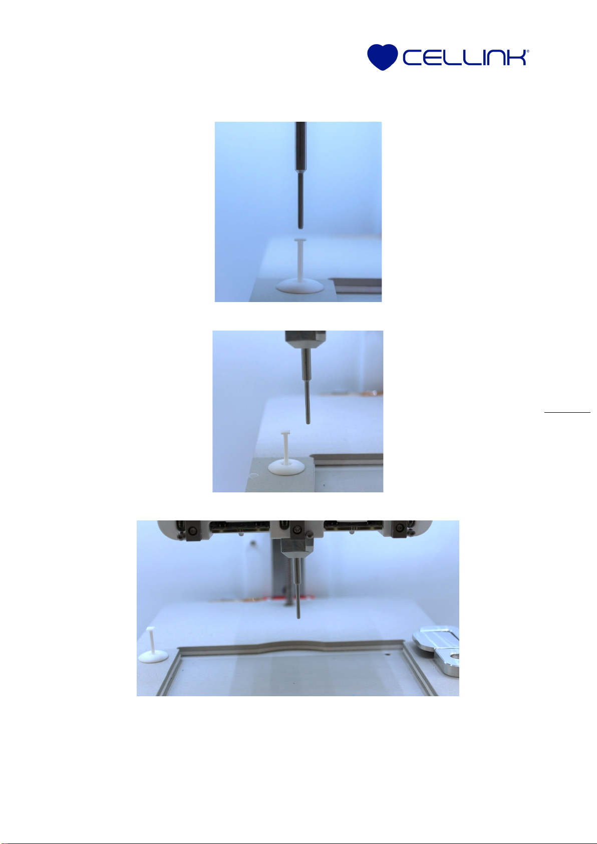
Step 1: Installing the surface probe station
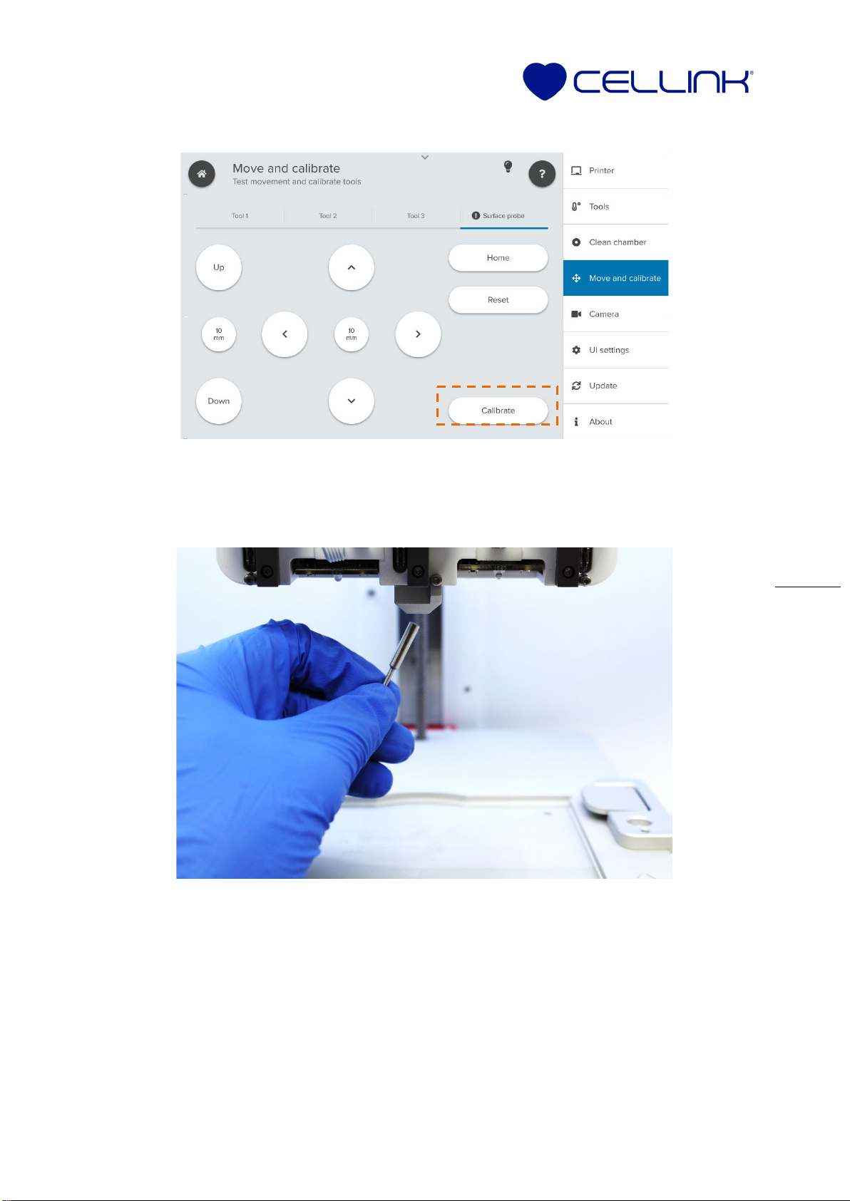
Step 2: Installing the Z-probe station
NOTE: Be careful not to damage the Z probe endstop during the hardware installation.
Excessive force can cause the lever to detach.
1.
Turn the BIO X off and remove all
printheads.
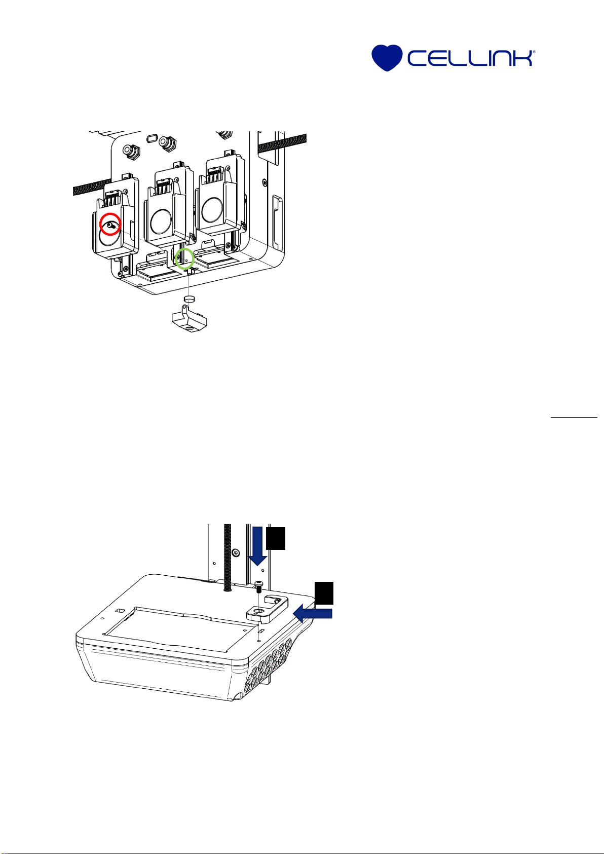
2. Unscrew the bottom mechanical endstop
screw of the second printhead, labeled by
the green circle in the diagram.
3. Remove the spacer and keep the M2 screw,
labeled by the red circle in the diagram.
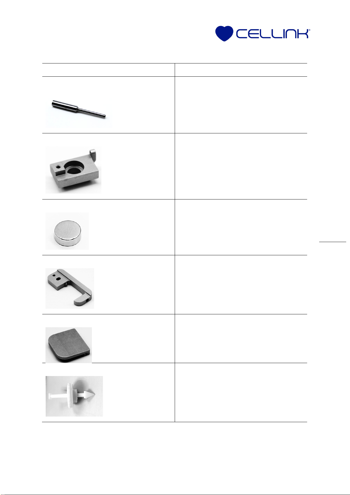
4. Insert the magnet into the surface probe
stabilizer. Polarity does not matter when
inserting the magnet.
5. Align the surface probe stabilizer and
magnet such that the surface probe
endstop is directly on top of the magnet.
6. Being careful not to bend the red switch,
press the stabilizer up and toward the back
of the printer.
7. Insert the M2 screw in the surface probe
stabilizer. Tighten it, making sure to not
overtighten.
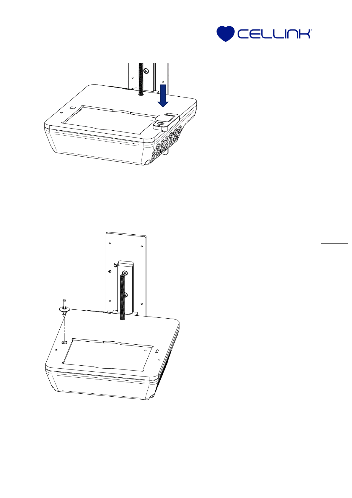
1.
Align the slot of the Z-station
base with the right M4 hole in the
print bed.
2. Place the supplied M4 screw into
the hole. Do not tighten.
3. Press the Z-station base firmly to
the left to align it with the print
bed.
4. Maintain pressure and tighten the
M4 screw.