Cembre LD-16B-RP User manual

1
RAIL DRILLRAIL DRILL
LD-16B-RP LD-16B-RPA LD-16B-RPE LD-16B-RPT
OPERATION AND MAINTENANCE MANUAL
(Translation of the original instructions)
ENGLISHENGLISH
22M051E_0423_6261424

2
INDEX page
WARNING .................................................................................................................................................................................................. 3
Compliance of use ................................................................................................................................................................................. 4
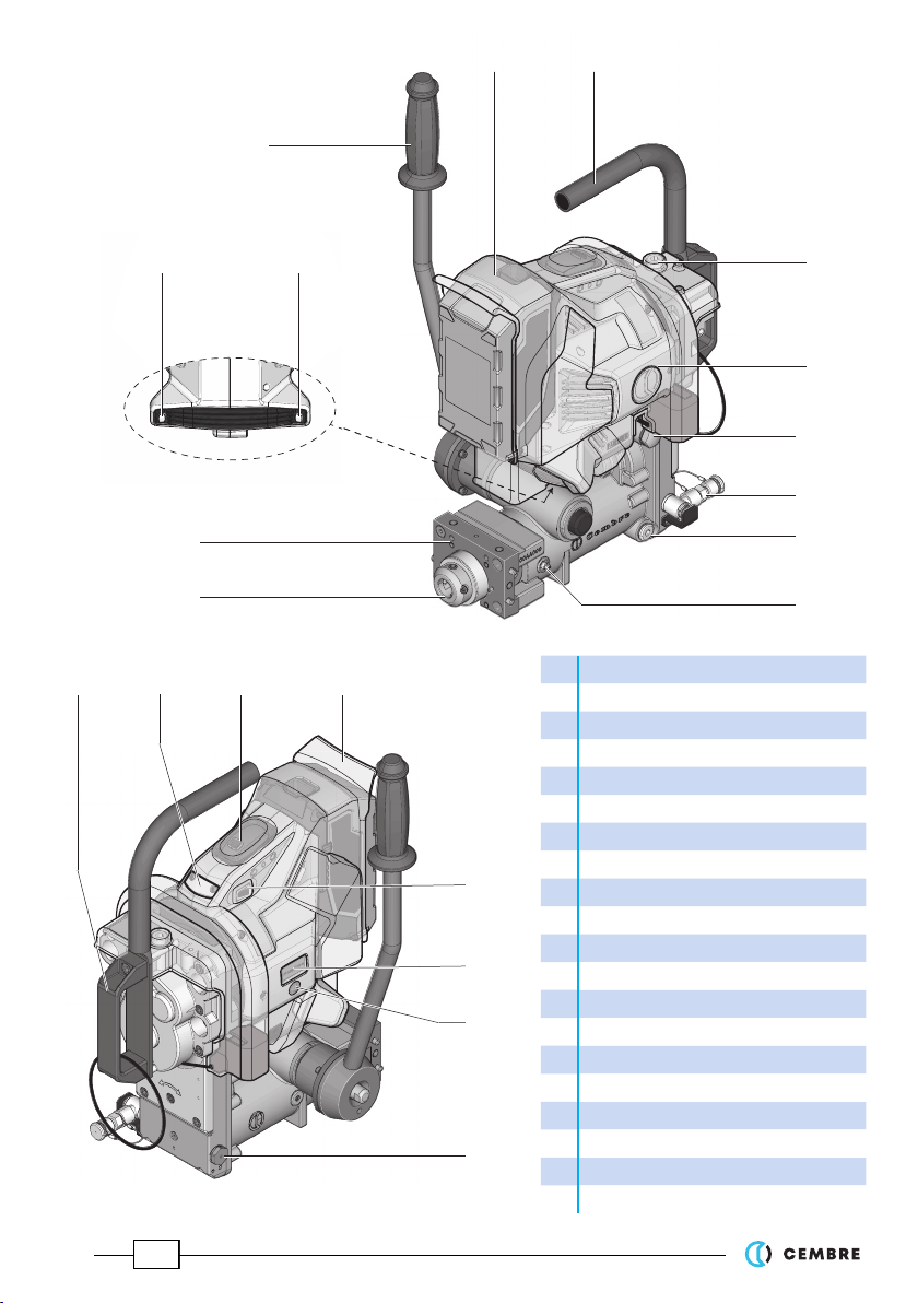
1. General characteristics............................................................................................................................................................. 6
2. Accessories supplied with the drill ...................................................................................................................................... 7
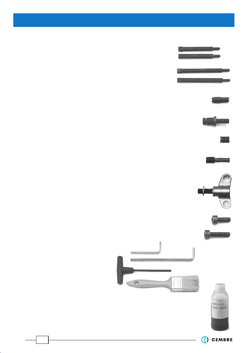
3. Accessories to be ordered separately ................................................................................................................................. 9
4. Spindle advance lever .............................................................................................................................................................. 13
5. Motor ON/OFF switch (EMERGENCY) ................................................................................................................................. 14
6. LED worklights ON/OFF switch............................................................................................................................................. 14
7. LED indicator................................................................................................................................................................................ 15
8. "Drilling assistance" function................................................................................................................................................. 15
9. Rechargeable battery ............................................................................................................................................................... 16
9.1) Using the battery charger ....................................................................................................................................................... 17
10. SR5000 coolant unit ................................................................................................................................................................. 17
11. Preparing the drill ...................................................................................................................................................................... 19
11.1) Assembling broach cutters with Quick push/turn shank............................................................................................ 19
11.2) Assembling broach cutters with Weldon shank.............................................................................................................. 20
11.3) Assembling spiral bits............................................................................................................................................................... 21
11.4) Assembling terminations on DBG-F2 clamping device ............................................................................................... 22
11.5) Assembly of DBG-F2 clamping device................................................................................................................................ 23
11.6) Fitting positioning templates .............................................................................................................................................. 23
11.7) Fitting "double sided" templates......................................................................................................................................... 24
11.8) Clamping the drill to the rail web......................................................................................................................................... 25
12. Drilling operation....................................................................................................................................................................... 26
12.1) Drill fitted with broach cutter ................................................................................................................................................ 26
12.2) Drill fitted with spiral bit.......................................................................................................................................................... 28
13. Alarms............................................................................................................................................................................................. 29
14. SPA positioning plate................................................................................................................................................................ 30
15. Storing the drill ........................................................................................................................................................................... 32
16. Maintenance ................................................................................................................................................................................ 33
17. Navigation menu ....................................................................................................................................................................... 36
18. Display alarms ............................................................................................................................................................................. 37
19. Return to CEMBRE for overhaul............................................................................................................................................... 38
Appendix “A”............................................................................................................................................................................................. 38

3
– Before using the rail drill, carefully read the instructions contained in this manual.
SAVE THESE INSTRUCTIONS: this manual contains important safety and operating instructions
for the rail drill.
– Do not use the rail drill for purposes other than those intended by CEMBRE.
– Never use a rail drill that is faulty, has been tampered with or which has been modified from its
original form.
– Degree of protection IP44M regarding the ingress of water into the motor and /or battery applies
only when the battery provided and rainproof cover are correctly used together.
Before use, always check:
• The precise positioning of the rainproof cover, especially around the battery area.
• The integrity of the rainproof cover, for example, the absence of cuts or abrasions; a damaged
cover must be replaced in order to avoid ingress of water and moisture into the motor and / or
the battery.
– When operating, stand in a stable, secure position and grip the drill firmly.
Be sure to work in good light conditions or with sufficient artificial lighting.
During drilling keep your hands outside the danger area.
Always wear protective glasses and working gloves.
Avoid wearing clothes which may present a risk to personal safety.
– Always remove the battery when servicing the drill, before performing any work in the area of
the spindle e.g removing cutting tools (broach cutters, spiral bits) assembling positioning tem-
plates, maintenance or cleaning.
Safety instructions for batteries:
– Protect battery from water and moisture!
– Do not expose batteries to naked flames!
– Do not use faulty or deformed batteries!
– Do not open batteries!
– Do not touch or short circuit battery contacts!
– A slightly acidic, flammable fluid may leak from defective Li-ion
batteries!
– If battery fluid leaks out and comes into contact with your skin,
rinse immediately with plenty of water. If battery fluid leaks out
and comes into contact with your eyes, wash them with clean water
and seek medical attention immediately!
– At the end of their life, always recycle batteries.
– Never discard batteries with domestic waste. They must be sent
to appropriate collection centres for disposal.
– If the machine is defective, remove the battery from the drill.
– Remove the battery from the machine to transport the machine.
– For transportation of Li-Ion batteries please refer to page 38.
WARNINGS

4
Definitions:
LD-16BN-RP LD-16BN-RPA
LD-16BN-RPE LD-16BN-RPT
(Rail drill without railweb clamping device)
LD-16B-RP LD-16B-RPA
LD-16B-RPE LD-16B-RPT
(Rail drill complete with DBG-F2 railweb
clamping device)
Compliance of use
– The device is a battery drilling machine intended for use in Railway applications to provideconsistent and accurate
holes in various rail types and railtrack equipments.
Any other use, or use deemed to be outside of the specification of the device shall be regarded as improper
use. In these instances the manufacturer/supplier shall not be liable for any damage resulting from improper use
and the user agrees to bear all risk.
– The device is manufactured in accordance with current technological standards and recognized safety rules.
However, danger to life and limb of the user or third parties/or damage to the device and other tangible assets
can arise during use.
– The device may only be used for its intended purpose and if in perfect working order, and it must be used
with appropriate consideration given to the safety and danger warning messages stated in the operating manual.
– Usage of the device for its intended purpose also incorporates compliance with the operating manual, including
the manufacturer‘s maintenance recommendations and specifications.

5
1 1
2
34
5
6
7
8
9
10
11
12
14
13 15
17
20
1Powerful LED worklights
2Spindle advance lever
3Rechargeable 36V Li-Ion battery
4Trasport handle
5Oil filler cap
636V DC motor unit
7Oil level indicator
8Coolant connection
9Cap with magnetic insert
10 Lubricator for spindle shaft
11 Front plate for assembling templates
12 Spindle shaft
13 Support handgrip
14 LED indicator
15 Motor ON / OFF switch (EMERGENCY)
16 Silicone rainproof cover
17 LED worklights ON / OFF switch
18 OLED Display
19 Capacitivetouchbuttonformenuselection
20 Air valve
Descriptions: FIG. 1
16
18
19

6
LD-16B-RP
LD-16B-RPE
LD-16B-RPT LD-16B-RPA
Rated drilling capacity
Ø
mm
(inch)
7 33 (9/32) (15/16)
7 13 (9/32) (1/2) with CEMBRE PE range spiral bits
13 33 (1/2) (1 5/16) with CEMBRE CY range broach cutters
Max drilling thickness
mm (inch)
50 (2)
Rated no load speed n0 (spindle)
min-1
260
Brushless electric motor V 36
Degree of protection (motor-battery)
IP 44M (EN 60529 Standard)
Weight (drilling machine only) kg (lbs) 14,1 (31)
Weight (with DBG-F2 and battery) kg (lbs) 19,2 (42.2)
Dimensions Ref. to page 38
Operating temperature °C (°F) -20 to +50 (- 4 to +122)
Recommended oil (100 ml)
(for gear sump) type SHELL SPIRAX S4 TXM SAE 10W-30
Air Noise (1) dB LpA 77,3 (A) LpCPeak 98,3 (C) LWA 89,2 (A)
Vibrations (2) m/s2ah 1,21 max.
Rechargeable battery type CB3680L (Li-Ion)
Voltage / Current / Energy V / Ah / Wh 36 / 8.0 / 288
Weight kg (lbs) 1.9 (4.2)
Battery charger type ASC145-
EU
ASC145-
UK
ASC145-
AUS/NZ
ASC145-
USA/CA
Input V / Hz (W) 220 - 240 / 50 - 60 (190) 115 / 60 (190)
Output V DC / A 10,8 - 36 / 8 max.
Weight kg (lbs) 0,6 (1.32)
In order to optimise the charge of the battery, the drill is equipped with a timer which disconnects power to
the motor when the continuous operating time threshold of 120 s has been exceeded.
(1) Directive 2006/42/EC, annexe 1, point 1.7.4.2 letter u
LpA = weighted continuous acoustic pressure level equivalent.
LpCPeak = maximum value of the weighted acoustic displacement pressure at the work place.
LWA = acoustic power level emitted by the machine.
(2) Directive 2006/42/EC, annexe 1, point 2.2.1.1
Weighted rootmeansquareinfrequencyoftheaccelerationtheupperlimbsareexposedto for each biodynamicreference
axis. Tests carried out in compliance with the indications contained in EN ISO 5349-1/2 Standard, and under operating
conditions much more severe than those normally found.
1. GENERAL CHARACTERISTICS

7
2.1) Guide bits for controlling the coolant system:
for broach cutters suitable for drilling thickness up to 25 mm
PP 1 (1 pc) diameter 7 mm.
PP 2 (1 pc) diameter 8 mm.
for broach cutters suitable for drilling thickness up to 50 mm
PPL 1 (1 pc) diameter 7 mm.
PPL 2 (1 pc) diameter 8 mm.
2.2) Spacer, type DPE, (1 pc) for controlling the coolant system, use with APE adapter for
special spiral bits.
2.3) Adapter, type ARE (1 pc) for external coolant connection, use with SR5000
coolant unit.
2.4) Grub screw, M8x10 (1 pc as a spare) for securing broach cutters or spiral bits
with Weldon shank on spindle shaft.
2.5) Transverse threaded pin (1 pc as a spare) for securing broach cutters or spiral bits
with push/turn shank on spindle shaft.
2.6) Wing nuts (2 pcs) complete with fixing washer for securing positioning inserts
type KPAF to front plate.
2.7) Screws M6x16 (4 pcs) for securing positioning templates to front plate.
2.8) Screws M6x25 (4 pcs) for securing special positioning templates type MPD... & MPR...
to front plate.
2.9) Range of tools:
5 mm Allen key (1 pc)
6 mm Allen key (1 pc)
4 mm T-handle Allen key (1 pc)
Brush (1 pc)
2.10) 100 ml oil bottle for gear sump.
Ref. to §16 for other details.
(Parts 2.1 to 2.10 are included in the "ACCESSORIES KIT ", Code Nr. 6004356)
2. ACCESSORIES SUPPLIED WITH THE DRILL

8
2.11) Type SR5000 coolant unit (1 pc)
Provides coolant fluid to the cutter during the drilling operation.
Consists of a tank complete with tube and maximum pressure valve,
fitted with a pump device for pressurisation.
2.12) Type CB3680L rechargeable battery (2 pcs)
36 V 8,0 Ah (LiHD Technology) Li-Ion, equipped with LED indicators
of the remaining battery life at any time by pressing the button.
2.13) ASC 145 -fast charger (1 pc)
Differs depending on geographic region.
Use to quickly charge the Li-Ion batteries supplied:
- Minimal current consumption in stand-by mode
- Management of the charging process by means of a processor
- “AIR COOLED”function for quicker cooling of the battery in case
of overheating.
2.14) Canvas bag type CVB-032 (1 pc)
Designed to store and protect the batteries and the battery
charger.
Can be separated into two parts for easy storage inside the drill case.
Optimal battery storage temperature is between 10°C and 30°C.

9
TDB 1 TDB 6 TDB 3
3.1) DBG-F2 device (*) with moving arm for clamping the drill to the rail
web and track fittings, complete with the following terminations:
– TDB 1: for switch blades and compound frogs.
– TDB 3: for repairing (adjusting) existing holes on rails for subsequent ap-
plication of electrical connections and for additional special applications.
– TDB 6: standard termination for rails and stock rails.
(*) already supplied with LD-16B-RP LD-16B-RPA LD-16B-RPE LD-16B-RPT drill type.
TDB 7
3.1.1) DBG-LF2 device
with moving arm complete with TDB 7 termination
for clamping the drill to girder rails and for additional
special applications.
3.3) VAL P24 plastic carrying case for storing the drill complete with the DBG-F2 and drilling accessoires.
VAL P24-CS wheeled plastic carrying case: VAL P24 with folding handle and wheels.
3.3.1) VAL LD-L metal case for storing the drill complete with the DBG-LF2 device, DBSN device and VAL MPA
tool case.
VAL LD-L
VAL P24-CS
3.2) DBSN device
Forclamping the drilltoflangerails, for use in conjunc-
tion with the MPAF templates.
Using this device the rail drill can remain clamped
in the drilling position even when trains pass over it.
3. ACCESSORIES TO BE ORDERED SEPARATELY

10
3.4) MPAF templates for positioning the drill on rails and stock rails
to enable drilling to be carried out according to the provisions of
railway boards standards e.g.:
– MPAF UIC54 on DRILLING AXIS of 54E1 rail
– MPAF UIC60 on DRILLING AXIS of 60E1 rail
• Contact CEMBRE for selection of other specific application ac-
cesories.
3.5) MPAU universal positioning template suitable for
repairing existing holes on various fittings, and for drilling
disused rails.
3.6) KPAF "double sided" templates with double face, enable
drilling on two types of rails with a single kit, simply by turning the
two inserts.
• Contact CEMBRE for selection of other specific application acces
sories.
3.7) SPA positioning plates for use in conjunction
with MPAF... positioning templates.
For drilling rail heads with a centre-to-centre
distance established in the Railway boards stan-
dards, without the need for marking out;
• Contact CEMBRE for selection of other specific
application accessories.
3.8) MRF clamp to be applied as a reference to the
head of rails for use in conjunction with SPA...
positioning plates; for in-line drilling of rail heads,
with established centre-to-centre distance.
3.9) VAL-MPA tool case for storing
the accessories indicated in 3.4 - 3.8, and the
cutting tools.

11
BROACH CUTTERS FOR RAILS IN STEEL QUALITY 7009001100 UIC 860.0
3.10) CY range broach cutters (with Quick push/turn shank)
CY broach cutters allow automatic cooling by means of the SR5000 unit supplied with the drill.
Contact CEMBRE for other types of broach cutters.
Broach
cutter
Required
guide bit
CY130
CY135
CY160
CY170
CY175
CY180
CY190
CY200
CY210
CY220
CY230
CY240
CY250
CY260
CY270
CY275
CY280
CY290
CY300
CY310
CY320
CY330
Ø
mm
13
13,5
14
16
17
17,5
18
19
20
21
22
23
24
25
26
27
27,5
28
29
30
31
32
33
CY140L
CY160L
CY170L
CY180L
CY190L
CY200L
CY210L
CY220L
CY230L
CY240L
CY250L
CY260L
CY270L
CY280L
CY290L
CY300L
CY320L
CY330L
MAX DRILLING THICKNESS
25 mm
LONG RANGE (L max = 88mm)
STANDARD RANGE
PPL 1
PPL 2
PP 2
MAX DRILLING THICKNESS
50 mm
PP 1
L max
Ø
Quick push/turn shank
O-ring
Broach
cutter
Required
guide bit

12
– The spiral bits in the PE range allow automatic cooling by means of the SR5000 unit supplied with the drilling
machine.
– All spiral bits in the PE range allow drilling of thickness up to 45 mm.
3.11) PE range spiral bits and adapters
SPECIAL SPIRAL BITS FOR RAILS IN STEEL QUALITY 700 900 1100 UIC 860.0
The cutting tools indicated in the tables guarantee optimum results.
For other type of tools, check the dimensional compatibility (particularly the size of the attachment and
the length).
3.12 LR2 biodegradable lubrocoolant
3 litre container. For optimum operation of both broach cutters and spiral bits.
Fill with water and lubrocoolant in a 5 % solution (4,75 l of water + 0,25 l of
lubrocoolant)
3.13 LR3 antifreeze concentrate
3 litre container. Added to the lubrocoolant mixture in the right concentration
will maintain its fluidity fluid in minus temperatures.
APED...
APE...
ø
L max
h
(*) PE... AR: special high quality spiral bit.
3l
Ø
mm
Spiral
Bit
L
max
mm
h
mm
Required
adapter
7PE70
76 1,2
APED70
7,1 PE71
72
8PE80
76
1,4
APED80
8,5 PE85
9PE90 APE 90
9,5 PE95 APE 95
10 PE100 APE100
11 PE110
1,6
APE110
12 PE120 APE120
13 PE130AR (*) APED130

13
The spindle is advanced by moving the lever (36) (Ref.
to Fig. a).
The lever is fitted with a release pawl (39) (Ref. to Fig. b).
which, when pressed, renders it independent of the hub
and hence the spindle;
The operator can therefore:
easily change the angular position of the lever without
movement of the spindle.
retrieve the stroke in phase of drilling (Ref. to Fig. c).
4.1) Adjustment of the advance lever
The movement of the lever must never be loose, for adjust-
ment proceed to tighten it by loading the cup springs by
means of the associated self-locking nut, after removing
the protective cap.
self-locking nut
b) - With the release pawl (39) pressed, the lever is released
from its hub and can repeat the previous travel without
the spindle moving.
c) - With the hub released, moving the lever towards
the operator produces a corresponding advance
of this spindle.
a) - Moving the lever (36) towards the operator
produces a corresponding advance of the
spindle.
39
4. SPINDLE ADVANCE LEVER
36

14
Two high efficiency LED worklights enable efficient illumination of the drilling area (e.g. in tunnels or outdoors at
night).
Use the ON/OFF switch (17) on the side of the motor switch to activate or deactivate the automatic illumination of
the lights on the front of the motor.
ON position: the lights turn on automatically at start-up and turn off automatically 20 seconds after the motor is
switched off.
OFF position: no automatic illumination, the lights remain off.
The motor switch (15) is placed on the motor in an easily visible position and can
be rapidly activated in case of emergency.
It is a tilt switch and provided with an interlock device to avoid unintentional start-ups.
The switch has two specific functions:
Start / Stop of the drill:
slide the interlock device forward (1) and
press the switch into operating position (2).
To stop the drill, return the switch to its cen-
tral position (0).
1
2
1
2
1
2
1
2
“Indexing” function:
is useful for easy access to the grub screws on the drill
spindle.
With one finger, keep the interlock device forward (1)
and with another repeatedly push the switch down (2).
With each press of the switch, the spindle rotates by
10°.
1
2
1
2
17
1
2
1
2
OFF in
central position
5. MOTOR ON/OFF SWITCH (EMERGENCY)
6. LED WORKLIGHTS ON/OFF SWITCH
1
2
1
2
15

15
7. LED INDICATOR
LED indicator
8. "DRILLING ASSISTANCE" FUNCTION
Thedrillfeaturesa circuitboardthatconstantlymonitorstheoperating
voltage, motor and battery current. This enables optimisation of the
electric motor's capability and consequently enables best possible
battery life, guaranteeing security and reliability.
An LED indicator is placed in an easily visible position on the motor
and has the dual function of:
Providing "Drilling Assistance" to the operator (Ref. to § 8).
Indicating any errors or operational anomalies of the machine
(Ref. to § 13).
The “drilling assistance” function has been developed and optimised for use with CEMBRE CY range Broach
Cutters (diameter from19 to 32 mm, ref. to § 3.10), on 800 and 900 quality steel rails (UIC 860.0).
The multiplicity of variables (hardness of the rail, typology and sharpness of the cutting tool in use) does
not permit all possible application criteria to be covered.
The “drilling assistance” function is not optimised for cutting tools of other manufacturers.
By responding to the changes in colour of the LED indicators (Ref. toTABLE 1), the operator is able to apply optimum
force on the spindle lever so as to obtain the maximum possible output, required to achieve predictable drilling
times by standard methods.
TABLE 1 ("Drilling Assistance" with CEMBRE CY range Broach Cutters, diameter from19 to 32 mm)
LED colour Force applied to the spindle advance lever Action
WHITE
OK
INSUFFICIENT
Spindle progress too slow
Increase force so as to turn on the
GREEN LED
GREEN OK
OPTIMUM *
Correct spindle progress
Maintain this progress for the
entire drilling process
RED
OK
EXCESSIVE
Spindle progress too fast
Reduce force so as to turn on the
GREEN LED
* Normally, using twist drill bits up to Ø 13 mm (Ref. to § 3.11) does not require a force that illuminates the
green LED. In such a case, it is however acceptable for the WHITE LED to remain illuminated.

16
Batteries are supplied with a charge ≤ 30%. To maximise energy level, it is necessary to fully recharge them
before use.
Only use the battery charger supplied with the drill.
Charge the battery by following the instructions provided in the battery charger manual, approximately
120 minutes are required to charge a fully depleted battery with ASC 145 fast charger.
Before inserting the battery, ensure that the Motor switch is in the central OFF position “0”: if not, the yel-
low LED on the indicator will be lit with a subsequent electronic lock of the drill (Ref. to §12) in order to avoid
involuntary start-ups. To restore function, remove the battery, move the Motor switch to the OFF “0” posi-
tion and reinsert the battery.
The battery is equipped with LED indicators that indicate the remaining battery life at any time by pressing the
adjacent button (C):
4 LEDs illuminated: fully charged
2 LEDs illuminated: 50 % capacity
1 LED flashing: minimum charge, the battery is almost depleted and needs
to be charged.The electronics protect the battery from any damage caused
by complete depletion.
Continuous overload causes deactivation due to overheating. In such a
case, allow the battery to cool down; if the battery feels hot to the touch,
it can be cooled down more quickly by inserting it into the relevant “AIR
COOLED”battery charger.
A completely charged battery provides 100% of its energy between -20°C
and + 50°C.
Removal of the battery:
- Retract the upper and lower parts of the rainproof cover (16) to expose the battery (Fig. a).
- Unlock the battery by the button (P) and remove it in an upwards direction (Fig. b).
Insertion of the battery:
- Retract the rainproof cover (16) and slide the battery down the guides until in place and locked by the button
(P) (Fig. b).
- Carefully and precisely reposition the rainproof cover (16) so as to cover the upper and lower parts of the bat-
tery (Fig. c).
9. RECHARGEABLE BATTERY
C
FIG. b
FIG. a FIG. c
P
16 16
16

17
H
Connect the SR5000 coolant unit to the attachment (35) on the drill by means of its quick-coupling (03) by passing
the hose through the O-Ring (36) so as to support the tap (02).
The use of the lubrocoolant supplied by CEMBRE, in the recommended concentrations, guarantees optimum life
of the cutting tools.
Consumption of the lubrocoolant depends both on the variable degree of opening of the tap (02) and the inner
pressure of the tank: it is therefore advisable to open the tap a little when the tank is at maximum pressure, while
it must be fully opened when the pressure in the tank is low.
When using the coolant system, pay careful attention to the instructions on the tank label.
To fill tank with lubrocoolant, turn handle anticlockwise approximately 2 turns to releas handle locking mechanism.
Remove handle/piston assembly from tank.
When drilling with a broach cutter, the delivery and shut-off of the lubrocoolant are controlled by the guide
bit; when drilling with a spiral bit, delivery and shut-off of the fluid must be effected manually by operating
the tap (02).
When the tank is not under pressure, check that the
maximum pressure valve is screwed right down.
Avoid leaving the SR5000 coolant tank under pressure
or exposed to sunlight for long periods of time.
35
02
03
01 – SR5000 coolant unit
02 – Tap
03 – Quick-coupling
20 – Vent valve
35 – Attachment coupling
36 – O-Ring
01
Detail of the
max pressure valve
10. SR5000 COOLANT UNIT
36
03
20
After removing or inserting the battery make sure of the precise repositioning
of the rainproof cover.
Check that the cover adheres laterally and covers the upper and lower parts of
the battery.
Wrong positioning of the rainproof cover can cause water ingress resulting in
damage to the motor and/or battery.
9.1) Using the battery charger
Carefully follow the instructions in the battery charger user manual.
Battery Rainproof cover

18
The drill is equipped with a coolant attachment valve (35) and a vent valve (20).
If under certain operating circumstances they need to be interchanged, proceed as follows:
Using a 17 mm spanner unscrew the vent valve from its seat.
Remove the protection plate and using the 4 mm T-handle Allen key provided with the drill, remove the appro-
priate coolant valve from its seat and fit into the vent valve seat, then assemble the protection plate.
Fit the vent valve into the removed coolant valve seat.
When temperatures fall below 0° C the lubrocoolant may freeze which could cause damage to the seals
contained in the drill coolant system.
It is therefore advisable, when storing the drilling machine,
to empty the lubrocoolant system completely.
Proceed as follows:
Disconnect the quick-coupling (03) from the coolant at-
tachment (35) on the drilling machine.
Tilt the machine so that the coolant attachment is at its
lowest point allowing natural drainage.
Operate the advancing lever (36) to advance and retract
the drilling spindle.
Gently shake the machine to expel all fluid.
ARE adapter
Adapter ARE
The ARE adapter is inserted in the quick-coupling (35) of the tank tube of the SR5000, it may be used:
To provide manual external cooling when cutters are used to enlarge existing holes, or when using spiral bits
not designed for automatic cooling.
To clean various parts of the drill, by means of the lubrocoolant pressure jet, e.g. the tool clamping seat in the
spindle shaft, seats for the template fixing screws, etc.
35
03
36
20
35

19
11. PREPARING THE RAIL DRILL
Always remove the battery when servicing the drill, before removing the cutting tools (broach cutters, spiral
bits and positioning templates etc).
Be careful of the broach cutter’s sharp edges. Always wear work gloves to avoid injury.
The drill spindle is factory-set to operate with CEMBRE CY range broach cutters fitted with Quick push/turn
coupling; use of broach cutters and twist drill bits fitted with Weldon shank only requires disassembly of the
transverse pin in the spindle (Ref. to §11.2).
11.1) Assembling broach cutters with Quick push/turn shank
Using the drive lever, turn the spindle so as to facilitate operation.
Insert the correct guide bit into the broach cutter (Ref. to § 3.10), from the shank end.
Insert the broach cutter into the spindle by positioning it so that the side flat lines up with the transverse pin
within the spindle, then rotate in a clockwise direction (2); the broach cutter will be locked without the need to
tighten the two grub screws (18).
Check that the guide bit slides freely by applying slight pressure on it.
To disassemble the broach cutter, turn in an anticlockwise direction and remove it from the spindle.
Before fitting, always check that the broach cutter is provided with the O-ring to ensure it secures correctly.
It is also possible to assemble broach cutters with Weldon shanks (Ref. to § 11.2).
1
2
PP.. guide bit
spindle transverse
pin
side flat
18
guide bits PP or PPL
O-ring
push turn

20
11.2) Assembling broach cutters with Weldon shank
Using the spindle lever, advance the spindle to
make the transverse threaded pin accessible;
if it is not in a easily-accessible position, insert
the battery and slide the Motor switch forward
(indexing function (Ref. to § 5) to make the pin
visible, then remove the battery.
With the 4mm T-handle Allen key, remove the
transverse threaded pin from the spindle (1) and
screw it into the "parking hole" in the clamping
device.
To protect the transverse threaded pin, tightly screw it into the “parking hole” (2) on the clamping device;
A spare pin is available in the ACCESSORIES KIT.
Using the advance lever, position the spindle shaft so that both grub screws (18) become accessible.
If necessary, insert the battery, slide the Motor switch forward to generate successive rotations of the spindle
(indexing function (Ref. to § 5), making the grub screws (18) visible, then remove the battery.
Insert the correct guide bit into the broach cutter (Ref. to § 3.10), from the shank end.
Unscrew grub screws (18) and insert the broach cutter into the spindle (1) in such a way that the two engaging
dogs on the shank of the broach cutter correspond to the grub screws.
Grub screws (18) have stops that prevent their complete unscrewing, do not force them past this stop.
Lock the broach cutter by fully tightening the screws using the 4 mm T-handle Allen key (2).
Check that the guide bit slides freely by applying slight pressure on it.
2
2
2
1
1
2
2
2
1
1
spindle
transverse
threaded pin
parking hole
18
engaging dogs
4 mm T-handle Allen key
spindle
This manual suits for next models
3
Table of contents
Other Cembre Drill manuals

Cembre
Cembre SD-15PR-ECO User manual

Cembre
Cembre LD-16B Manual

Cembre
Cembre LD-1P-ECO User manual

Cembre
Cembre LD-1PY-ECO User manual

Cembre
Cembre SD-15P-ECO User manual

Cembre
Cembre LD-41P User manual

Cembre
Cembre SD-9P-ECO User manual

Cembre
Cembre LD-2EY User manual

Cembre
Cembre LD-41PY User manual

Cembre
Cembre SD-9P-ECO User manual
Popular Drill manuals by other brands

ALDI
ALDI WorkZone WB 12-2 user manual

Dexter Laundry
Dexter Laundry 300SD2-23.5 instruction manual

Hitachi
Hitachi DS18DSAL - 18V 1/2" Driver Drill 460 In/Lbs... instruction manual

Draper
Draper PT810ID instructions

ETC Tools
ETC Tools EID-710 Original instructions

Gude
Gude GTB Series Translation of original operating instructions