Cembre LD-2EY User manual

RAIL DRILL
TYPE
PATENTED
LD-2EY
ENGLISH
OPERATION AND MAINTENANCE
MANUAL
This manual is the property of
Cembre
.
Any reproduction (in full or in part) is forbidden without the prior written permission of
Cembre
.
Cembre
reserve the right to modify the specifications in this manual without prior notice.
Cembre Ltd.
Dunton Park
Kingsbury Road, Curdworth - Sutton Coldfield
West Midlands B76 9EB (Great Britain)
Tel.: 01675 470440 - Fax: 01675 470220
E-mail: [email protected]
www.cembre.co.uk
Cembre S.p.A.
Via Serenissima, 9
25135 Brescia (Italia)
Telefono: 030 36921
Telefax: 030 3365766
E-mail: [email protected]
www.cembre.it
Cembre S.a.r.l.
22 Avenue Ferdinand de Lesseps
91420 Morangis (France)
Tél.: 01 60 49 11 90 - Fax: 01 60 49 29 10
B.P. 37 - 91421 Morangis Cédex
E-mail: [email protected]
www.cembre.fr
Cembre España S.L.
Calle Verano, 6 y 8 - P.I. Las Monjas
28850 Torrejón de Ardoz - Madrid (España)
Teléfono: 91 4852580
Telefax: 91 4852581
E-mail: [email protected]
www.cembre.es
Cembre AS
Fossnes Senter
N-3160 Stokke (Norway)
Phone: (47) 33361765
Telefax: (47) 33361766
E-mail: [email protected]
www.cembre.no
Cembre GmbH
Heidemannstraße 166
80939 München (Deutschland)
Telefon: 089/3580676
Telefax: 089/35806777
E-mail: [email protected]
www.cembre.de
Cembre Inc.
Raritan Center Business Park
181 Fieldcrest Avenue
Edison, New Jersey 08837 (USA)
Tel.: (732) 225-7415 - Fax: (732) 225-7414
E-mail: [email protected]
www.cembreinc.com
www.cembre.com
07 M 053 U
Certified Environmental
Management System Certified Occupational
Health & Safety
Management System
Certified Quality
Management System
cod. 6261216

134
Ref. LD-2ENY:
basic drill without clamping device
Ref. LD-2EYGR:
(LD-2ENY + DBG-GR)
basic drill complete
with railweb clamping devi-
ce type DBG-GR
Ref. LD-2EY:
(LD-2ENY + DBG-Y)
basic drill complete
with railweb clamping
device type DBG-Y
INDEX
page
Rail drill type LD-2ENY ..............................................................................................2
1. General characteristics..........................................................................................2
2. Accessories supplied with the rail drill...................................................................3
3.
Optional accessories (to be ordered separately)...................................................4
4.
Type SR5000 coolant unit....................................................................................10
5. Spindle advancing lever.......................................................................................12
6. Preparing the rail drill...........................................................................................13
7.
Rail drill type LD-2EY ........................................................................................15
8. Drilling..................................................................................................................19
9. Example of other rail drill applications.................................................................22
10. Special applications for
Cembre
rail drills..........................................................22
11. Storing the rail drill...............................................................................................23
12. Warnings..............................................................................................................24
13. Maintenance........................................................................................................25
14. Return to
Cembre
for overhaul..........................................................................29
Appendix “A”..............................................................................................................27
Appendix “B”..............................................................................................................
28

2
33
1. GENERAL CHARACTERISTICS
– Drilling capacity:................................................................................∅9/32" to 1 1/2"
(with special twist drill bits: hole diameters of 9/32" to 1-1/8" on rails up to 3 1/2" thick)
(with broach cutters: hole diameters of 3/4" to 1-1/2" on rails up to 2 3/4" thick)
– Speed without load:........................................................................................ 310 rpm
– Electric motor:
–
single phase, double insulation
–
supply voltage:
........................................................................................120 VAC / DC
– power rating:
......................................................................................................1800 W
– protection against overheating caused by a current overload and against unintentional
start up following a drop in voltage, by means of an automatic switch equipped with
thermal cut-out and underpower relay.
– Weight:.................................................................................................................31 lbs
– Weight:
with “DBG-Y” clamping device
..............................................................38 lbs
– Recommended gear sump oil: MOBIL DTE OIL LIGHT
or
ESSO TERESSO 32
or equivalent
– For "Air noise" and "Risk due to vibration", see page 28.
RAIL DRILL TYPE LD-2ENY
NOTES ATTENTION
–
Before using the rail drilling, carefully read the instructions contained
in this manual.
SAVE THESE INSTRUCTIONS: this manual contains important safety
and operating instructions for the drilling machine.
–
The degree of protection of the drilling machine against moisture
is classified “ordinary" (EN 50144-1 Standard).
Donotexposetheraildrillingtorainandmoisture;possibleinfiltrations
of water inside the electric motor determines the risk of electric
shocks.
Mobileelectricdevices usedoutdoormustbe connectedtothe
supply
by interposing a safety interrupter for breakdown current.
–
DISCONNECT always the power supply when servicing the drill:
before removing the broach cutters, spiral bits, positioning templates
etc.
–
During drilling keep your hands outside the danger area.
–
Always wear protective glasses and working gloves.
–
Avoid wearing clothes which may present a risk to personal safety.

3
2.1) Pilot bits for controlling the cooling system:
for use with short broach cutters (7/8 " depth of cut)
– 1 pc PPC 2
for use with long broach cutters (2 " depth of cut)
– 1 pc PPL 2
2.2) Spacer, type DPE, for use with spiral bits and APE adaptor
for controlling the cooling system, do not required for APED adaptor.
2.3) Adapter, type ARE, for external cooling, to be used with the
SR5000 cooling unit.
2.4) Grub screw, M8x10
– 4 pcs for clamping cutters or bits on the spindle shaft.
2.5) Socket head cap screws, M6x16
– 4 pcs for securing positioning shoes to the front plate.
2.6) Socket head cap screws, M6x25
– 4 pcs for securing special positioning shoes to the front plate.
2.7) Range of tools:
– 1 pc 5 mm allen key
– 1 pc 6 mm allen key
– 1 pc 4 mm allen key with handle
– 1 pc brush (for removing the drilling swarf)
2.8) 4.7 floz (140 ml) oil tank for
the gear reduction.
2.9) Type SR5000 coolant unit.
(Accessories from pos. 2.1 to pos. 2.8 are included in the
“Kit of accessories for LD-2ENYY” having the code 6001909)
11
10
09
08
07
06
05
04
03
02
01
Electric motor
Brush
Handle
Handgrip
Cap
Carrying handle
Spindle advance lever
O-ring
Lever release pawl
Complete coolant connection
Complete body
1
2
1
1
1
1
1
1
1
1
1
Item QtyDescription
Code No
12
14
15
16
17
18
19
11
09
10
20
13
21
22
-
6001209
6900060
6001731
6001198
6001397
6001144
6001146
6340160
6001195
6001818
22
21
20
19
18
17
16
15
14
13
12
Electric plug
Magnetic cap
Screw M 4x8
Guard
Lubricator
Complete air valve
Front plate
Drilling spindle
M 8x10 grub screw
Transparent inspection cover
Automatic switch
1
1
2
1
1
1
1
1
2
1
1
32
2. ACCESSORIES SUPPLIED WITH THE RAIL DRILL
Item QtyDescription
Code No
6001368
6001422
6380316
6380330
6001210
6001238
6001262
6360480
6001176
6001428
6001997

4
3.1.1) "DBG-LY" device specific for clamping the rail drill
to the girder rails (for example 128 GR or GGR 118). With
the specific shoes allows the positioning on both sides of
the rails, complete with theTDB 3 termination.
3.1) "DBG-Y"device withmovingarmforclamping
theraildrilltotherailweb and trackfittings,complete
with the TDB 6 termination.
* Always supplied with rail drill ref. LD-2EY
3.1.2) "DBG-GR" device for clamping the rail drill in
correspondance of guard rail,completewiththeTDB
1termination.
Always supplied with rail drill ref. LD-2EYGR
FIG. 28 – RAIL DRILL ASSEMBLY
08
07
06
05
04
03
02
01
When ordering spare parts always give the following information:
- spare part code
- spare part description
- rail drill model
- rail drill serial number.
31
TDB 6
TDB 3
3. OPTIONAL ACCESSORIES (to be ordered separately)

5
3.3) "VALLD" steel carrying case for
accommodating the complete drill with
the clamping device.
22 1/2" (L) x 13 1/2" (W) x 17 1/2" (H)
3.5) "MPAU"UNIVERSALRAILSHOEforrailorforspecial
applications such as drilling #20 high speed switch points
(positioning not automatic).
3.5.1) "MPAU-10" UNIVERSAL SHORT RAIL SHOE for
rail or for special applications (positioning not automatic).
3.2) "TST 50" two stage template
(to be used with specific DBG-AY clamp)
This device enables the drilling of 150 lb and alu-
minium composite contact rails from one side.
Restart of work stroke: 1,97”
Typical application:
– Aluminium composite rail.
– 150 lbs contact rail.
3.4) "VAL MPA" suitable for storage of rail shoes,
cutters and accessories
• 15 1/2” (L) x 13 3/4” (W) x 2 1/4” (H)
FIG. 27 – “DBG-Y” RAIL WEB CLAMPING DEVICE
6001154
6700524
6040421
6001155
6001156
6760378
6340612
6900314
6650144
6900348
6760222
6140082
6001775
6001751
6001756
6001754
6340160
6380310
6001150
6001658
6001659
6001152
6520422
6140085
6001145
6001281
Threaded bush
ø14 Circlip
ø10 Circlip
Spacer
Pin
ø 8 x 50 pin
M5 ball dowel
M 6 x 18 screw
Spring washer
M 8 x 25 screw
ø4 x 10 pin
ø1,8x35 Split pin
TDB 6 termination
Blocking side
Clamping support left shoulder
Clamping support right shoulder
M 8 x 10 grub screw
Clamping handle knob
Blocking lever
Compl. blocking screw
Thickness
Adjusting bush
Cup spring
ø2,5 x 16 Split pin
Clamping support
Drilling reference rod
1
1
1
1
1
2
2
4
4
2
1
1
1
2
1
1
1
2
1
1
1
1
1
1
1
1
30
29
28
27
26
25
24
23
22
21
20
17
16
13
12
11
10
09
08
07
06
05
04
03
02
01
Code N° Item Description Qty
14
19
17
12
11
13
16
15
04
05
08
09
07
25
20
26
23
21
22
24
29
30
10
06
27
28
18
01
02
03
30

6
3.5.2) "MPAF..." SPECIFIC RAIL SHOES
Suitable for positioning the drill on running and guard
rails.
Enable the automatic position of the machine onthe drilling axis
(H) of each specific rail.
•
Note: Please contact
Cembre
for other types of rail.
RAIL SHOES DRILLING ON GUARD RAILS
RAIL SHOES DRILLING ON RUNNING RAILS
RAIL SHOES DRILLING ON GIRDER RAILS
H
H
(*) to be used with PFA 1 arbour extension and PPL5 Pilot Bit.
100 LB ARA-B 2 1/4”
112/115/119 LB RE 2 5/8”
115 LB-RE-3132 3 1/32”
132 LB RE 3 9/32”
136 LB RE 3 1/4”
MPAF 100 LB ARA-B GR
MPAF 115/119 LB RE GR
MPAF 115 LB-RE-3132
MPAF 132 LB-RE-3932
MPAF 136 LB-RE-314
RAIL SHOE
(Using DBG-GR clamp)
TYPE OF
RAIL H
(inches)
128/149 LB 3”
128/149 LB 2 3/4”
149 LB 2 3/4”
GGR 118 2 3/8”
RI60/RI60N 2.87”
NP4A/NP4AM 2.87”
180-105 LB 2.87”
MPAF 128/149 LB GR
MPAF 128/149 LB GR 234
MPAF 149 LB GR 234
MPAF GGR 118
MPAF RI 60 N
MPAF NP4AM
MPAF BA9101
TYPE OF
RAIL H
(inches)
RAIL SHOE
(Using DBG-LY clamp
and 2” depth cutters)
40 LB ASCE 3 1/16"
60 LB ASCE 3 1/16"
80 LB ASCE 2 3/16”
85 LB ASCE 2 17/64”
85 LB PRR 2 1/16”
85 LB PS 2 15/64”
90 LB ARA-A 2 9/16”
90 LB ASCE 2 45/128”
100 LB ARA-A 2 3/4”
100 LB ARA-B 2 65/128”
100 LB ASCE 2 65/128”
100 LB DY 2 5/8”
100 LB NYNH&H 2 39/64”
100 LB RE 2 45/64”
100 LB RE-HF 2 45/64”
100 LB PRR 2 9/32”
100 LB PS 2 31/64”
105 LB DY/110 LB RE
2 43/64”
112/115/119 LB RE 2 7/8”
122 CB 2 7/8”
127 LB DY 3 1/8”
130 LB RE/HF-A 2 3/4”
130 LB RE-HF 3 1/16"
130 LB HF-B 3 3/8”
130 LB PS 2 3/4”
131 LB RE 3 1/2”
132 LB RE 3 3/32”
133 LB RE 3”
136 LB RE 3 3/32”
136 LB LE VAL 3 1/16”
140 LB RE/140 PS
3”
141 LB AB/ 141 LB RE
3 3/32”
152 LB PS 3 3/4”
155 LB PS rail 3 3/8”
MPAF 40 LB ASCE
MPAF 60 LB ASCE
MPAF 80 LB ASCE
MPAF 85 LB ASCE
MPAF 85 LB PRR
MPAF 85 LB PS
MPAF 90 LB ARA-A
MPAF 90 LB ASCE
MPAF 100 LB ARA-A
MPAF 100 LB ARA-B
MPAF 100 LB ASCE
MPAF 100 LB DY
MPAF 100 LB NH
MPAF 100 LB RE
MPAF 100 LB RE-HF
MPAF 100 LB PRR
MPAF 100 LB PS
MPAF 105 LB DY
MPAF 115/119 LB RE
MPAF 122 CB
MPAF 127 LB DYM
MPAF 130 LB RE
MPAF 130 LB RE-HF
MPAF 130 LB HF-B
MPAF 130 LB PS
MPAF 131 LB RE
MPAF 132 LB RE
MPAF 133 LB RE
MPAF 136 LB RE
MPAF 136 LB LVM
MPAF 140 LB RE
MPAF 141 LB AB
MPAF 152 LB PS *
MPAF 155 LB PS *
TYPE OF
RAIL H
(inches) RAIL
SHOE
In the case of a breakdown contact our Area Agent who will advise you on the problem
andgiveyou the necessary instructions onhowtodispatch the tool toournearest service
Centre; if possible, attach a copy of the Test Cerificate supplied by
Cembre
together with
the tool or, if no other references are available, indicate the approximate purchase date
and the tool serial number.
29
15. RETURN TO
Cembre
FOR OVERHAUL

728
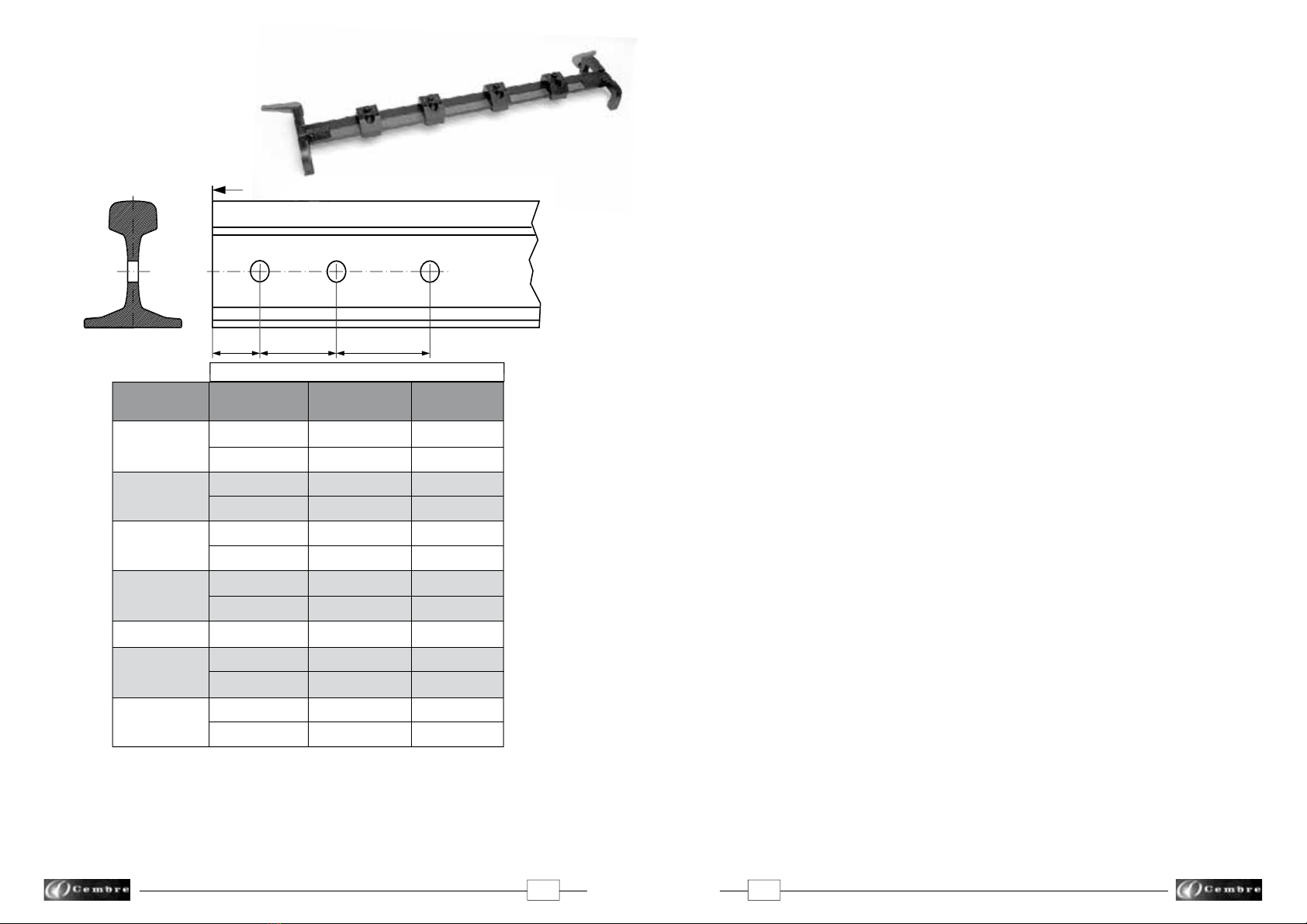
3.6) JOINT BAR POSITIONING GAUGES
Positioning gauges MRF-Y... for drilling joint bar
holes at pre-defined distances between rail end
and holes center lines.
2 21/32" 7 1/4" 5 1/2"
3 1/2" 6" 6"
2 21/32" 7 1/4" 5 1/2"
3 1/2" 4 3/4" 4 3/4"
2 23/32" 6" 7"
3 1/2" 6" 6"
3" 6" -
2 7/16" 5" -
2 7/16" 7" -
2 3/8" 7" -
2 3/4" 6 3/4" 6 3/4"
2 11/16" 5 1/2" 5 1/2"
3 1/2" 6" 6"
POSITIONING
GAUGE A B C
MRF Y10
MRF Y11
MRF Y12
MRF Y13
MRF Y14
MRF Y15
MRF Y16C
MRF Y10: suitable for drilling the following rails 100ARA-B, 115 and 119 LB RE
MRF Y11: suitable for drilling the following rails 100 ARA-B, 105 DL&W
MRF Y12: suitable for drilling the following rails 115, 119, 132, 136, 140 LB RE, 130 and 155 PS
MRF Y13: suitable for drilling the following rails 80, 90 LBASCE and 100ARA-A
MRF Y14: suitable for drilling the 85 LBASCE rail
MRF Y15: suitable for drilling the 130 LB RE and 136 LE.VAL rails
MRF Y: universal positioning gauge for all rail sizes
•
Note: other positioning gauge sizes available upon request.
A
C
R
R
RA
IL
END
B
APPENDIX “B”
Air noise (DIRECTIVE 2006/42/EC, Annexe 1, point 1.7.4.2, letter "u"):
–The continuous equivalent weighted level (A)
of noise pressure at the working place LpA is equal to .................................85,8 dB (A)
– The maximum value of instantaneous weighted noise
pressure C at the working place LpCPeak is lower than....................................130 dB (C)
– The level of noise force produced by the machine LWA
is equal to.....................................................................................................96,6 dB (A)
Protection of operators against risksof exposure to noise during work.
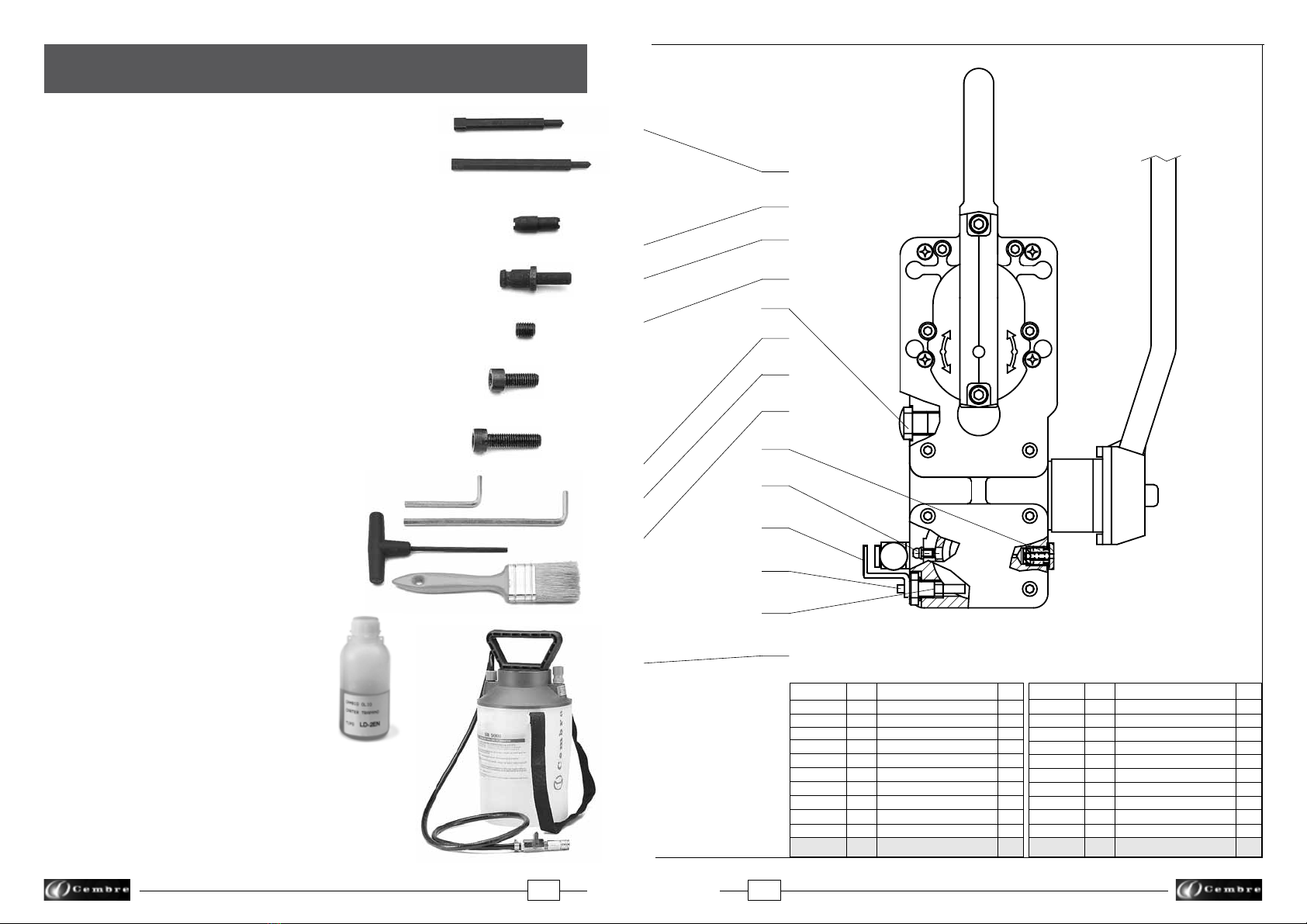
Cembre
drills type LD-2EY are designed and constructed according to EEC directives
80/1107 and 86/188 relating to the protection of operators against risks arising from ex-
posure to chemical, physical and biological agents during work, and with particular regard
to the risk of exposure to noise.
Thishas enabled a rangeof drills tobe manufactured for drillingrails and trackequipment,
at reduced noise levels.
The degree of exposure of an operator to noise produced from this equipment depends
on the duration of the loading times and the intervals between exposures, and finally on
the number of holes made within the space of one working day.
For example, an operator using the drill correctly for making holes 19 mm in diam., with
a type RCV 190 broach cutter on rails classified as UIC 60, quality 900, producing up to
400 holes/day, the daily personal exposure to noise, due solely to the use of the drill, is
less than 80 dB (A); under similar conditions producing 700 holes/day, the daily exposure
to noise would be 82.1 dB(A).
Since noise levels vary according to the many different operating conditions,
Cembre
engineers are available to give further details on the correct use of the drills.
Risks due to vibration (Directive 2006/42/EC, Annexe 1, point 2.2.1.1).
The weighted root mean square acceleration value to which the arms of an operator are
subjected when using the drill machine does not exceed 2,5 m/s2.
HOLES DISTANCES

827
All the broach cutters allow automatic cooling by means of the SR5000 unit supplied with
the drills.
3.7) BROACH CUTTERS
These cutters rapidly produce high quality, accurate
holes in a single pass. The automatic lubrocooling
system reduces friction and eliminates heat build up
duringthedrillingoperation.Understandardconditions
a broach cutter can drill 40-50 holes, depending on
the hardness of the rail.
15128
15130
15132
15234
TSC 1 1/8"
15138
TSC 1 1/4"
TSC 1 5/16"
15144
15146
TSC 1 1/2"
TSC 3/4"
01354
01355
01356
01357
01358
01359
01360
01361
01362
01363
01364
12218
3-12224
3-12226
3-12228
3-12230
3-12232
3-12236
BROACH
CUTTER PILOT
BIT
HOLE
DIAME-
TER
(inches)
7/8"
15/16"
1"
1 1/16"
1 1/8"
1 3/16"
1 1/4"
1 5/16"
1 3/8"
1 7/16"
1 1/2"
3/4"
7/8"
15/16“
1“
1 1/16"
1 1/8"
1 3/16“
1 1/4"
1 5/16“
1 3/8"
1 7/16"
1 1/2"
9/16"
3/4"
13/16"
7/8"
15/16"
1"
1 1/8"
MAX.
DEPTH OF CUT
(inches)
Ref. PPC 2
Ref. PPL 2
3-10528
2 "
7/8 "
3 "
APPENDIX “A”
Factors which influence the number of holes that can be made according to the
tool used.
– Hardness of the material to be drilled.
– Thickness to be drilled.
– Stability of the drill clamp and correct assembly of the cutter/bit.
– Suitable lubrocooling (lubrication/cooling) tokeep the temperature of thetoollowso
asnottocompromisetheefficiencyofthecutting edges, whilst at the same time facilitating
the removal of the swarf.
– Contact time of the cutting edges of the cutter/bit with the material to be drilled;
bear in mind that the faster the hole is made the greater the efficiency.
– Observance:
1) Commence drilling by exerting light pressure on the advancing lever, progres-
sively increasing and then relaxing it when the tool is in the exit phase.
2) Avoidpressurejoltsandonlyadvanceaccordingtothedrillingdiametertoavoidscratch-
ing the material or damaging the cutting edges of the cutter/bit.
3) Remember that a tool with efficient cutting edges requires a pressure lower than that
applied to one with which a certain number of holes have already been made.
4) When holes are made close to raised lettering on the rails, commence drilling
with very light pressure until the lettering disappears, to avoid possible breakage of the
tool.
5) Bear in mind that when operating on very hard rails, as in the case of quality 1100 steel,
it is advisable to increase the lubrocoolant flow rate.
FIG. 26 – CHANGING THE BRUSHES
Brush

26
9
with adapter
3.8) SPECIAL SPIRAL TWIST BITS
Using these bits guarantees optimum performance during the drilling operations. As a
rule, under normal conditions, a spiral bit can drill 70-100 holes, depending on the hard-
ness of the rail.
For tools of other types, check the dimensional compatibility (particularly the size of the attachment and the length).
APED...
Diam.
3.9) "LR2"LUBROCOOLERCONCENTRATE,1or5gallonsforoptimum
operation of both the broach cutters and the spiral bits.
This product of vegetable origin, to be watered down in the percentage
95% water, 5% oil, will provide a white colour mixture very effective for
the drilling operations resulting in no heating at the rail or the drilling
machines.
3.10) "LR 3" ANTIFREEZE CONCENTRATE of 1 or 5 gallons added
to the lubrocooling mixture with the right percentage will maintain the
lubrocooling mixture fluid in negative temperature consitions.
LR 3
LR 2
PE70
PE95 C
PE130
PE160
PE190
PE220
PE130L-AR
PE3/4”-L1-AR
PE7/8”-L1-AR
PE1”-L1-AR
PE1-1/8”-L1-AR
PE1-1/4”-L1-AR
SPIRAL
BIT ADAPTER
HOLE
DIAMETER
(inches)
9/32”
3/8”
1/2”
5/8”
3/4”
7/8”
1/2”
3/4”
7/8”
1”
1 1/8”
1 1/4”
SPACER
APED70
APED 3/8 Y
APED 130
APED135/165
without adapter
without adapter
APED 130
without adapter
without adapter
without adapter
without adapter
without adapter
included in the APED 70
included in the APED 3/8 Y
included in the APED 130
included in the APED 135/165
DPE
DPE
included in the APED 130
DPE
DPE
DPE
DPE
DPE
not required
not required
not required
not required
not required
not required
TST50 + DBG-AY
TST50 + DBG-AY
TST50 + DBG-AY
TST50 + DBG-AY
TST50 + DBG-AY
TST50 + DBG-AY
ADDITIONAL
ACCESSORIES
without adapter
Every 50 hours of operation
13.1.3) Checking the bolts
Check and retighten all bolts.
13.1.4) Lubrication (Ref. to Figs. 27 and 28)
Lubricate the spindle support housing by means of the appropriate lubricator (18), the
screw (07) of the clamping device with moving arm DBG-Y.
13.1.5) Cleaning of the coolant filter (Ref. to Fig. 25)
The coolant system of the drilling machine is provided with anti-impurity filter; should an
evident decrease of the flow of the lubrocoolant be verified, it could be necessary to clean
it in the following way:
– Using a 14mm key, unscrew the coupling (02).
– Extract the filter and clean it carefully.
– Reassemble the filter into the coupling (02) as shown in the Fig. 25, fully tighten the
coupling.
13.2) ORDINARY MAINTENANCE OF THE MOTOR
Every 50 hours of operation
13.2.1) Changing the brushes (Ref. to Fig. 26)
After disconnecting the power plug check the degree of wear of the brushes; if necessary
replace them by proceeding as follows:
– Unscrew with a screwdriver the two screws located underneath the protective covers.
– Remove the two protective covers.
– Replace the brushes.
– Reassemble the two protective covers.
– Tighten the locking screws.
anti-impurity filter
02
FIG. 25 –
CLEANING OF THE COOLANT FILTER
Diam.

1025
Before servicing or maintenance, stop the motor and disconnect the plug
from the electric source
After first 10 oerating hours, proceed with sump oil change, as follows:
(Ref. to Fig. 28)
– Remove the cap with the magnetic insert (21).
– Remove oil filler cap (07).
– Make sure that all the oil comes out by slightly tilting the drill.
– Clean up the cap (21) (see § 13.1.2).
– Reassemble the cap (21).
– Fill the sump with oil to the level indicator (see § 13.1.1) using the oil supplied with the
drilling machine; it will be necessary to use about 4.7 floz oil.
– Replace the filler cap (07).
13.1) ORDINARY MAINTENANCE OF THE MACHINE (Ref. to Figs. 24 and 28)
Every 20 hours of operation
13.1.1) Topping up oil
With the drill switched off and placed on a flat surface, check the oil level in the crankcase
by looking through the appropriate transparent inspection cover (13).
The level must be approximately half way up the cover; if the level is low top up the oil
by unscrewing the cover (07) at the top of the crankcase and adding the quantity of oil
required.
Only use the oil grade recommended in § 1.
Never use regenerated or used oil.
The oil must be clean.
13.1.2) Removal of metallic residue
from the crankcase
When the drill is positioned as shown
inFig.24unscrewtheappropriatecap,
with magnetic insert (21) on which any
metallic residue will have collected.
Carefully clean the magnetic insert
with a clean rag and screw it back in
the appropriate housing.
▲
!
FIG. 24 – REMOVAL OF
METALLIC RESIDUE
21
13. MAINTENANCE
ThetypeSR5000coolantunitconsistsofatankcompletewithtubeandmaximumpressure
valve (01), fitted with a pump device for pressurisation, which must be connected to the
attachment (35) on the drill by means of its quick-coupling (03).
Thedeliveryandshut-offofthelubrocoolantarecontrolledautomatically,when
drilling
witha broach cutter, from thepositionof the guide bit; when drilling with a spiral bit,
deliveryandshut-off ofthe fluidmust beeffected manuallyby operatingthe tap(02).
The use of the lubrocoolant supplied by
Cembre
, in the recommended concentrations,
guarantees optimum use of the drilling tools.
Consumption of the lubrocoolant depends both on the variable degree of opening
of the tap (02) and the inner pressure of the tank: it is therefore advisable to open
the tap a little when the tank is at maximum pressure, while it must be fully opened
when the pressure in the tank is low.
When using the coolant system, pay careful attention to the instructions on the tank label.
Warning:
●
When the tank is not under pressure, check that the bush on the maximum pres-
sure valve is screwed right down.
●
To fill tank with lubrocoolant, turn handle anticlockwise approximately 2 turns to
release handle locking mechanism. Remove handle/piston assembly from tank.
02
03 35 17
01
Detail of the
max pressure valve
FIG. 3 – COOLANT UNIT
01– Tank complete with hose
and max. pressure valve
02– Tap
03– Quick-coupling
17– Vent valve
35– Attachment valve
4. Type SR5000 COOLANT UNIT (Ref. to Fig. 3)

11 24
12.1) Always disconnect the electrical supply when working on the drill to replace cutters,
bits, positioning jigs and/or end pieces for maintenance.
12.2) Regularly check for correct tightening (torque) of the fixing screws of the drilling
tools and positioning shoes.
12.3) Avoid pressure jolts on the advancing lever during drilling.
12.4) Always make sure that the drilling swarf is properly removed before starting to drill
a new hole.
12.5) Incomplete clamping of the drill on the rail to be drilled may lead to the breakage
or accelerated wear of the drilling tool and damage to the spindle shaft bearings.
12.6) If it is necessary to operate the drill without the cutter inserted, remove the locking
grub screws from the spindle shaft.
12.7)
Avoid leaving the SR5000 tank under pressure and exposed to sunlight for long
periods of time.
12.8) Should the DBG-Y clamping device be removed, make sure that by reassembling
it, the 2 locking screws with 4 washer are firmily fastened.
12. WARNINGS
ARE adaptor
FIG. 5 – ARE ADAPTOR
35
03
4.1) ARE adaptor
ForusewithtypeSR5000 coolant unit.The ARE adaptor is inserted in the quick-coupling
of the tank tube (refer to Fig. 5), it may be used to provide manual external cooling
when cutters are used to enlarge existing holes, or when using spiral bits not de-
signed for automatic cooling.
IfnecessarytheARE adaptorcanalsobeusedtocleanvariousparts of the drill, by means
of the lubrocoolant pressure jet, e.g. parts such as the tool clamping seat in the spindle
shaft, seats for the fixing screws, etc.
● The drill is equipped with a coolant attachment valve (35) and a vent valve (17)
which are located as shown (Fig. 3).
If under certain operating circumstances they need to be interchanged, proceed
as follows:
– Using a 17 mm hexagonal spanner unscrew the vent valve from its seat.
– Using the 4 mm allen key provided with the drill, remove the appropriate coolant
valve from its seat and fit into the vent valve seat.
– Fit the vent valve into the removed coolant valve seat.
● When temperatures fall below 0° C the
lubrocoolant may freeze which could
cause damage to the seals contained
in the drill coolant system.
It is therefore advisable, when storing
the drilling machine, to empty the
lubrocoolant system completely.
Proceed as follows (Fig. 4):
– Disconnect the quick coupling (03)
from the coolant attachment (35) on
the drilling machine.
– Tilt the machine so that the coolant
attachment is at its lowest point - allowing
for natural drainage.
– Operate the advancing lever (36) to
advance and retract the drilling spindle.
– Gently shake the machine to
expel all fluid.

23 12
FIG. 23 - STORAGE CASE
VAL MPA
VAL LD
LD-2EY
FIG. 6
Thespindleisadvancedbymovingthelever
(36) (See Fig. 6 a). The lever is fitted with
a release pawl (39) which, when pressed,
rendersitindependentofthehubandhence
thespindle;theoperatorcanthereforeeasily
varytheangularpositionoftheleverwithout
movement of the spindle (Fig.6).
6c - With the hub released, moving the lever
towards the operator causes a corre-
sponding advance of the spindle.
6a - Movingthelever(36)towardstheoperator;
corresponding advance of the spindle.
FIG. 7
5.1) Adjustment of the advance lever
The movement of the lever must never be
loose, for adjustment proceed to tighten it by
loading the cup springs by means of the as-
sociated self-locking nut, after removing the
protective cap (see Fig. 7).
SELF-LOCKING NUT
6b - With the release pawl (39) pressed, the lever is
releasedfromitshubandcanrepeattheprevious
travel without the spindle moving.
11. STORING THE RAIL DRILL
When work has been completed, store the drill by proceeding as follows:
11.1) Depressurise the tank of the SR5000 coolant unit (see § 4), close the tap (02) on
the hose and disconnect the quick-coupling (03).
11.2) Carefully clean the machine, particularly in the spindle area, removing machining
waste (swarf, etc.) and any deposits of lubrocoolant.
11.3) Fully withdraw the spindle.
11.4) Place the rail drill and the SR5000 coolant unit in a sealed place free from dust,
moisture and the risk of accidental impact.
For better protection
Cembre
recommends the use of the VAL LD metal case designed
for this purpose (see § 3.3). The DBG-Y moving arm device allows the drill to be housed
and locked in the case. A suitable housing is also provided in this VAL LD for the VAL
MPA box containing the most commonly used accessories.
5. SPINDLE ADVANCE LEVER (Ref. to Fig. 6)

13 22
6.1) Assembling the broachcutters (Ref. to Figs. 8-11)
6.1.1) Insert the pilot bit in the cutter from the side of the spigot.
6.1.2) Using the lever (36), position the spindle shaft (07) so that both grub screws (18)
become accessible and sufficient space is provided to insert the cutter; if necessary rotate
the spindle shaft manually and sufficiently by inserting the 4 mm male hexagon key in the
appropriate intermediate gear housing (30) in the crankcase of the drill corresponding to
the feed handle (71) (see Fig. 11).
6.1.3) Insert the cutter in the spindle shaft so that the two engaging dogs on the cutter
spigot line up with the grub screws.
6.1.4) Clamp the cutter by fully tightening the grub screws by means of the 4 mm male
hexagon key.
6.1.5) Check that the guide bit slides freely by applying slight pressure on it.
6.2) Assembling the special spiral bits (Ref. to Figs. 9 - 11)
6.2.1) Using the advance lever, position the spindle shaft so that both grub screws beco-
me accessible and sufficient space is provided to insert the spiral bit; if necessary rotate
the spindle shaft manually and sufficiently by inserting the 4 mm male hexagon key in the
appropriate intermediate gear housing in the crankcase of the drill corresponding to the
feed handle (71) (see Fig. 11).
Engaging dogs
07
18
FIG. 8 – ASSEMBLING THE CUTTERS
10. SPECIAL APPLICATIONS FOR
Cembre
RAIL DRILLS
*= Application developed for narrow chairs
1 = For drilling 56 lb aluminium bar manufactered by FOSTER
2 = For drilling 84 lb aluminium bar manufactered by FOSTER
3 = For drilling 84 lb aluminium bar manufactered by PORTER
DBG-LYoverrailclamp
andthespecific shoes
(combination) allows
thepositioningon both
sidesoftherails.Useof
2" depth of cut broach
cutters
– Use on girder rail (Ref. to Fig. 21 a-b, example for 128 GR or GGR 118)
– Use on running rails (Ref. to Fig. 22)
(narrow passage of the articulated arm)
Drilling by the guard rail DBG-GR
over rail clamp equipped with TDB 1 termination.
9. EXAMPLE OF SPECIAL
RAIL DRILL APPLICATIONS
FIG. 22
FIG. 21b – Side 2FIG. 21a – Side 1
MPAF 85 LB ASCE
Pilot bit PPC 2
Pilot bit PPL 2
Short type broach cutter
Maximum drilling thickness: 7/8"
Long type broach cutter
Maximum drilling thickness: 2"
6. PREPARING THE RAIL DRILL

1421
FIG.10 – ASSEMBLING THE
BIT-SPACER
UNIT
FIG. 9 – ASSEMBLING THE SPIRAL BITS
DPE
07
71
30
FIG. 11 – MANUAL SPINDLE
ROTATION
Start drilling
with discharge of
lubrocoolant
Drilling
Finish drilling
with removal of swaf and
switching off of
lubrocoolant
Approach
FIG. 20 – COOLING DRILLING WITH BROACH CUTTER
8.3) Rail drill fitted with special spiral bit
Follow the sequence described in § 8.1, taking care to position the rail drill on the rail by
keeping the spindle fully withdrawn. Bear in mind that the cooling circuit, instead of be-
ing automatically opened and closed by the pilot bit, is kept open at all times by the DPE
spacer fitted on the spigot of the spiral bit; it must therefore be activated, by opening the
tap (02), before starting to drill, then switched off after drilling by closing the tap.
FIG. 20a – COOLING DRILLING WITH SPIRAL BIT
* use only for APE..., do not required for APED...
6.2.2) Insertintothespindle shaft,theDPE spacerrequiredtoactivatethecoolantsystem.
If it necessary to use an APE... adaptor, the bit must first be fitted into the corre
sponding APE adaptor and locked with the appropriate grub screw, then the DPE
spacer inserted.
Note: Adaptors type APED… (e.g. APED 3/8Y) do not require use of DPE
spacer.
6.2.3) Insert the bit-spacer unit in the spindle shaft so that the two engaging dogs on the
bit spigot line up with the grub screws. Press the bit-spacer unit home against
theinnerseatofthespindle:thiswillenabletheDPEspacertoopenthecoolant
circuit (see Fig. 10).
6.2.4) Clampthebitbyfullytighteningthetwogrubscrews(18)usingthe4mmmaleallenkey.
DPE *
18
Bits PE ... (e.g. PE70)
Bits PE ... (e.g. PE 190)
APE ...
DPE spacer * Spiral bit
APE or APED adaptor
* use only for APE, not required for APED

15 20
7. TYPE LD-2EY RAIL DRILL
FIG. 12 – RAIL DRILL LD-2EY FIG. 19 – DRILLING
02
39
36
automatic switch
The reference LD-2EY relates to the entire LD-2ENY rail drill complete with the clamping
device DBG-Y for clamping it to the rail web and the track fittings (Ref. to Fig. 12).
The DBG-Y device consists of:
– Clamping unit.
– Type TDB 6 termination.
– Socket head cap screws M8 x 25 (2 pcs).
– Spring washers (4 pcs).
– Reference pin.
reference
pin
TDB 6
M 8x25 screws
and spring washers
8.1.5) Proceedtodrillbyinitiallyapplyinglightpressureonthelever(36),increasing
thepressureprogressively,avoidingjolts,andfinallyrelievingthepressurein
the exit phase. When drilling close to raised markings on the rail the initial
pressuremust be extremely light untilthe markings disappear,otherwise the
cutter may be damaged.
8.1.6) The pilot bit will enable the lubrocoolant to be discharged throughout the drilling
process.
8.1.7) When drilling has been completed, fully retract the spindle, stop the motor by
pressing the automatic switch (position "0"), and make sure that drilling
swarf is removed before recommencing drilling.
8.1.8) After drilling it is advisable to remove all swarf from the tool and spindle area.
8.2) Rail drill fitted with “long” type broach cutter (depth of cut 2").
Follow the sequence described in § 8.1, taking care to position the drill on the rail by
keeping the spindle fully withdrawn.

19 16
7.2) Assembly of the DBG-Y clamping device on the drill
The DBG-Y clamping device is fitted to the front plate of the drill, centred by means of the
reference pin supplied and secured with the two socket head cap screws M8x25 (35) also
supplied. The assembly is illustrated in Fig. 14.
FIG. 13 – ASSEMBLY OF THE TERMINATION
7.1) AssemblingoftheterminationoftheDBG-Ydevicewithmovingarmforclamping
the drill to the rail web and track fittings.
The termination TDB 6 of the DBG-Y device, with moving arm, have been designed for
adaptationtothedifferentoperatingconditionsontherailsandtrackfittings;theirassembly
is shown in Fig. 13.
•
When disassembling the TD termination ensure that, after removing the pivot, the
complete assembly is slid away downward without acting on the holding plate.
holding plate
Makesurethatthemainsvoltagevaluecorrespondstothevalueonthemachine
rating plate.
Switch on the cooling system before starting the rail drill (§ 4).
8.1) Rail drill fitted with “short” type broach cutter (depth of cut 7/8")
The drilling sequence may be started with the drill fitted with the broach cutter (§ 6.1),
positioning shoe (§ 7.3), the drill being clamped to the rail (§ 7.4), as follows:
8.1.1) Connectthefemalequick-coupling of the SR5000 coolant systemtomalecoupling
(35) on the drill.
8.1.2) Open the tap (02) fitted on the tank tube.
8.1.3) Using the lever (36) bring the guide bit almost in contact with the rail (Fig. 17a);
keeping the release pawl (39) pressed, release the lever from its cup and return it to the
initial position (Fig. 17b), which will enable the travel of the lever (36) to be used in the
most advantageous way.
8.1.4) Connect the electric plug and press the automatic switch (position "I") (Fig. 18)
V
!
V
!
▲
!
CAUTION: the automatic switch is equipped
withprotection against motor overheating and with
an underpower relay; should the motor overheat or
there is a fall in voltage below the relay cut-out set-
ting, the switch will move into the "0" position. At
this stage, if the conditions are correct, the switch
will have to be re-set manually.
FIG. 18
AUTOMATIC SWITCH
<>
Fig. 17a Fig. 17b Fig. 17c
36
39
8. DRILLING (Ref. to Figs. 17 - 18 -19)

18
17
FIG. 16 – POSITIONING OF THE RAIL DRILL
7.3) Assembly of the positioning shoes (Ref. to Fig. 15)
7.3.1) The type MPAF .. and MPAU positioning shoes are secured to the front plate (04)
of the drill by means of the two socket head cap screws M 6x16 supplied.
DBG-Y Clamp
reference pin
04
FIG. 15 – ASSEMBLY OF THE POSITIONING SHOES
2 screws M6x16
MPAF...
MPAU
Drilling machine
front plate
35
7.4) Clamping to the rail web (Ref.to Fig. 16)
Thespecialshapeof the positioning shoes, each correspondingtothetypeof rail, enables
the drill to be positioned quickly, accurately and safely on the element to be drilled.
To position the drilling machine, complete with the clamping termination (§ 7.1) and the
positioning template (§ 7.3) suitable for the type of rail to be drilled, proceed as follows:
7.4.1) Withdraw the spindle shaft (07) completely by means of the lever (36).
7.4.2) Bring the moving arm (03) of the clamping device into the fully open position by
means of the handwheel (11).
7.4.3) Place the machine on the rail at the point where the drilling is to be carried out, and
clamp it by tightening the handwheel (11) right down: the positioning shoe will
automaticallypositionthecutterorspiralbitinlinewiththedesiredaxis;ifaccuratepo-
sitioningrelativetothelongitudinalaxisoftherailisrequired,usethereferencepin(18).
11
03
36
07
18
FIG. 14 – ASSEMBLY OF THE
TYPE “DBG-Y” CLAMP
This manual suits for next models
2
Table of contents
Other Cembre Drill manuals

Cembre
Cembre SD-15P-ECO User manual

Cembre
Cembre SD-9P-ECO User manual

Cembre
Cembre LD-16B Manual

Cembre
Cembre SD-15P-ECO User manual

Cembre
Cembre LD-41P User manual

Cembre
Cembre SD-15PR-ECO User manual

Cembre
Cembre SD-9P-ECO User manual

Cembre
Cembre LD-1PY-ECO User manual

Cembre
Cembre LD-41P User manual

Cembre
Cembre LD-16B-RP User manual