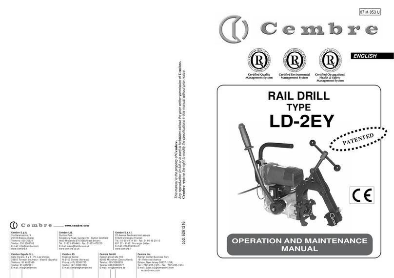
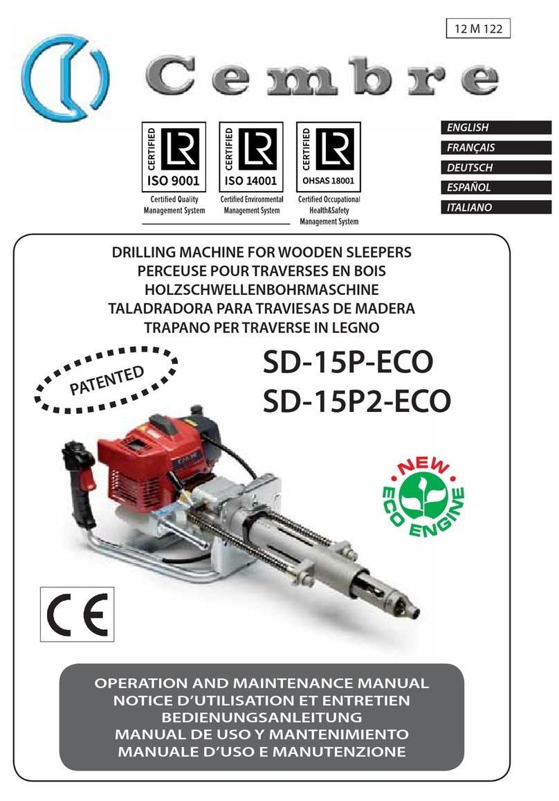
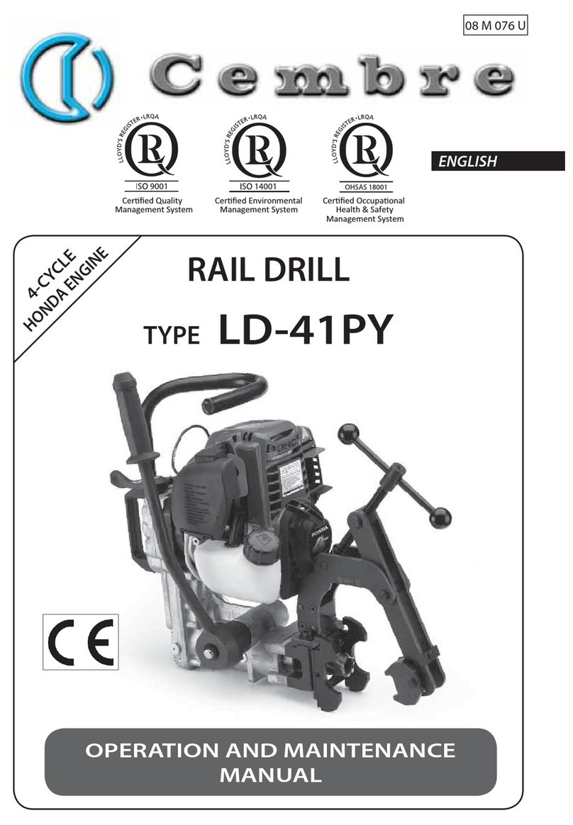
Cembre SD-19BR User manual

1
BATTERY DRILLING MACHINE FOR WOODEN SLEEPERS
PERCEUSE SUR BATTERIE POUR TRAVERSES EN BOIS
AKKU-HOLZSCHWELLENBOHRMASCHINE
TALADRO A BATERíA PARA TRAVIESAS DE MADERA
TRAPANO A BATTERIA PER TRAVERSE IN LEGNO
SD-19BR SD-19BRA SD-19BR2E SD-19BRT
SD-19BR-RP SD-19BR-RPA SD-19BR2-RPE SD-19BR-RPT
18 M 243
ENGLISH
FRANÇAIS
DEUTSCH
ESPAÑOL
ITALIANO
OPERATION AND MAINTENANCE MANUAL....................................6
NOTICE D’UTILISATION ET ENTRETIEN........................................... 23
BEDIENUNGSANLEITUNG................................................................... 40
MANUAL DE USO Y MANTENIMIENTO........................................... 57
MANUALE D’USO E MANUTENZIONE............................................. 74

2
Dimensioni in mm
6
1
2
3
5
10
8
12
13
16
22 21
9
11
7
14
9
4
17
4
3
18
20
19
15
23
Version -RP (RAINPROOF)
FIG. 1
BILD 1

3
❷
❶
❷
❶
❷
❷
90°
90°
❶
❷
❶
❶
FIG. 2
BILD 2
FIG. 3
BILD 3
1
5
3
16
FIG. 4
BILD 4
FIG. 5
BILD 5

4
24
6
CS-EU..
SD-19BR...
n
o
p
25
n
p
qo
P
8
Version -RP (RAINPROOF)
FIG. 6
BILD 6
c
P
OFF
b
FIG. 8
BILD 8
FIG. / BILD 7
a
25
25 23
23
23

5
FIG. 9
BILD 9
FIG. 10
BILD 10
FIG. 11
BILD 11

6
WARNING
– Before using the drilling machine, carefully read the instructions contained
in this manual. SAVE THESE INSTRUCTIONS: this manual contains important
safety and operating instructions for the drilling machine.
– EnsureappropriatePersonalProtectiveEquipments
(PPE) are used including protective glasses, working
glovesandsafetyshoes.Avoidwearingclotheswhich
may present a risk to personal safety.
– During drilling keep your hands outside the danger area.
– Do not use the drilling machine for purposes other than those intended by Cembre.
– Never use a drilling machine that is faulty, has been tampered with or which has been modi-
fied from its original form.
– Always remove the battery when servicing the drilling machine, or before replacement of
the auger or TPM guard nozzle.
– When operating, stand in a stable, secure position and grip the drilling machine firmly.
– Be sure to work in good light conditions or with sufficient artificial lighting.
Safety instructions for batteries:
– Protect battery from water and moisture!
– Do not expose batteries to naked flames!
– Do not use faulty or deformed batteries!
– Do not open batteries!
– Do not touch or short circuit battery contacts!
– A slightly acidic, flammable fluid may leak from defective Li-Ion
batteries!
– If battery fluid leaks out and comes into contact with your skin,
rinse immediately with plenty of water. If battery fluid leaks out
and comes into contact with your eyes, wash them with clean
water and seek medical attention immediately!
– At the end of their life, always recycle batteries.
– Never discard batteries with domestic waste.They must be sent
to appropriate collection centres for disposal.
– If the machine is defective, remove the battery from the machine.
– Remove the battery from the machine to transport the machine.
– For transportation of Li-Ion batteries please refer to page 22.
ENGLISH

7
1. GENERAL CHARACTERISTICS
Rechargeable battery:
Type CB3662L (Li-Ion)
Voltage / Current / Energy V / Ah / Wh 36 / 6,2 / 223,2
Weight kg 1,6
Drilling Machine:
SD-19BR SD-19BR-RP
SD-19BRA SD-19BR-RPA
SD-19BRT SD-19BR-RPT
SD-19BR2E
SD-19BR2-RPE
Rated drilling capacity
Ø
mm
28
Drilling thickness
mm
200 *
Rated no load speed n0 (spindle)
RPM
700
Brushless electric motor V 36
Weight with battery
Weight with battery ( RP versions )
kg
kg
16.8
17.4
Dimensions Ref. to page 23
Operating temperature °C (°F) -20 to +50 (- 4 to +122)
Supplied TPM guard nozzle type TPM200-26 ** TPM190-24 **
Air Noise (1)
Air Noise (1) ( RP versions )
dB
dB
LpA 80.4 (A) LpCPeak 97.5 (C) LWA 88.4 (A)
LpA 77.6 (A) LpCPeak 94.4 (C) LWA 88.5 (A)
Vibrations (2) m/s2ah 1.36 max.
* Using Cembre PV... augers series with standard lenght of 325 mm. Depending on the PV... auger usage, higher drilling
thicknes-
ses are possible (Ref. to § 10).
** TPM200-26: suitable for augers having ø max. 20 mm and centering for ø 26 mm plate hole.
TPM190-24: suitable for augers having ø max. 19 mm and centering for ø 24 mm plate hole.
(1) Directive 2006/42/EC, annexe 1, point 1.7.4.2 letter u
LpA = weighted continuous acoustic pressure level equivalent.
LpCPeak = maximum value of the weighted acoustic displacement pressure at the work place.
LWA = acoustic power level emitted by the machine.
(2) Directive 2006/42/EC, annexe 1, point 2.2.1.1
Weighted root mean square in frequency of the acceleration the upper limbs are exposed to for each biodynamic
reference axis. Tests carried out in compliance with the indications contained in EN ISO 5349-1/2 Standard, and
under operating conditions much more severe than those normally found.
ENGLISH

8
2. DESCRIPTION
2.1) Compliance of use
– Thedeviceisadrillingmachineintendedexclusivelytoperformverticalholesonrailwaywooden
sleepers. It can be used both as a portable tool and in combination with the specific support
trolley.
Any other use, or use deemed to be outside of the specification of the device shall be regarded
as improper use. In these instances the manufacturer/supplier shall not be liable for any damage
resulting from improper use and the user agrees to bear all risk.
– The device is manufactured in accordance with current technological standards and recognized
safety rules. However, danger to life and limb of the user or third parties/or damage to the device
and other tangible assets can arise during use.
– The device may only be used for its intended purpose and if in perfect working order, and
itmust beusedwithappropriateconsiderationgiventothesafetyanddanger warningmessages
stated in the operating manual.
– Usage of the device for its intended purpose also incorporates compliance with the operating
manual, including the manufacturer‘s maintenance recommendations and specifications.
SD-19BR SD-19BRA SD-19BR2E SD-19BRT : standard version of the drilling machine, the
degree of protection of the drilling machine against moisture is classified“ordinary" (EN 50144-1
Standard).
Do not expose the sleeper drilling machine to rain and moisture; possible infiltrations of
water inside could damage the electric motor, battery and electronic card.
SD-19BR-RP SD-19BR-RPA SD-19BR2-RPE SD-19BR-RPT: RAINPROOF version of the drilling
machine provided with a RAINPROOF silicone cover that protects the motor-battery from the
ingress of water and humidity.
Protection of the electric motor and/or battery from water ingress is guaranteed only with
the battery provided and with the rainproof cover correctly placed.
ENGLISH
Battery charger:
SD-19BR
SD-19BR-RP
SD-19BR2E
SD-19BR2-RPE
SD-19BRT
SD-19BR-RPT
SD-19BRA
SD-19BR-RPA
Type ASC-ULTRA-
EU ASC-ULTRA-
UK ASC30-36-
AUS ASC-ULTRA-
USA/CAN
Input
Power
V / Hz
W
220 - 240 / 50 - 60
290
220 - 240 / 50 - 60
85
115 / 60
290
Output V / A 14,4 - 36 / 6,5 max. 14,4 - 36 / 3 max. 14,4 - 36 / 6,5 max.
Weight kg 0,97

9
2.2) Drilling machine (Ref. to Fig. 1):
1- TPM... Guard Nozzle: stainless steel threaded centering device for attachment to the guard (2).
Alternative guard nozzle are available with different diameters, to suit different size hole (Ref.
to § 10.2).
2 - PRM-UNdetachableguard:stainless steeltelescopic element, controlledby thereturnsprings,
which provides protection for the auger. The lower end is threaded for attachment of the TPM
nozzle.
3 - Latch: rotated through 90° to remove the PRM-UN guard for easy replacement of the auger.
4 - Return springs: to assist the retraction of the auger from the sleeper on completion of the
drilling operation and to reduce operator effort.
5 - Depth adjusting gauge: graduated scale on the fixed guard to determine the desired hole
depth.Automatically stops the travel of the auger at the desired depth.
6 - Transport handle: to comfortable transport the drilling machine and joining element to the
support trolley.
7 - LED work lights ON/OFF Switch: to activate or deactivate the illumination of the LED work
lights (9) on the handlebar (Ref. to § 3.2).
8 - Motor ON/OFF/ON Switch (EMERGENCY): is placed on the motor in an easily visible posi-
tion and can be rapidly activated in case of emergency (Ref. to § 3.1).
9 - High efficiency LED work lights: enables efficient illumination of the drilling area (e.g. in
tunnels or outdoors at night).
10 - Control handgrip: to control the drilling machine during operation (Ref. to § 3.3).
11 - CB3662L rechargeable battery: Li-Ion 36 V 6,2 Ah (LiHD Technology) (Ref. to § 4).
12 - Handgrip: left side.
13 - OLED display: switches on automatically when the machine is started and automatically
switches off after a set time of non-operation (Ref. to § 3.5).
14 - Capacitive touch button: for menu selection (Ref. to § 3.5).
15 - Electric Motor: 36 V Brushless.
16 - Emergency lever for quick auger release: if necessary, this lever allows immediate release
of the auger from the machine, which can then be removed from the working area.
17 - Fixed guard: stainless steel guard protecting the spindle, featuring a graduated depth gauge.
18 - MND spindle: featuring an automatic quick lock mechanism suitable for augers with Ø 14
mm shank.
19 - Motor start button (Ref. to § 3.3).
20 - Mechanical interlock (Ref. to § 3.3).
21 - Right signalling LED (Ref. to § 3.4).
22 - Left signalling LED (Ref. to § 3.4).
23 - Rainproof Cover: silicone cover, only for -RP drilling machine variants.
ENGLISH
10
Rechargeable battery type CB3662L
36 V 6,2 Ah Li-Ion, equipped with LED indicators
of the remaining battery life at any time by pressing the button.
Fast charger type ASC-ULTRA
Differs depending on geographic region.
Use to quickly charge the Li-Ion batteries supplied:
- Minimal current consumption in stand-by mode
- Management of the charging process by means of a processor
-“AIR COOLED”function for quicker cooling of the battery in case
of overheating.
Canvas bag type CVB-032
Designed to store and protect the batteries and the battery
charger. Can be separated into two parts for easy storage
inside the machine case.
2.3) Accessories supplied with the drilling machine
ENGLISH

11
3.1) ON/OFF/ON Switch (EMERGENCY)
Is located on the motor in an easily visible position and can be rapidly
activated in case of emergency.
There are 3 positions available:
CENTRAL POSITION: machine OFF.
FORWARD (1): machine in stand-by, ready for drilling
(right rotation of the spindle ).
BACKWARD (2): machine in standby, ready for the reverse
rotation of the spindle; useful for unlocking an auger that is
jammed inside the sleeper (left rotation of the spindle ).
AUTO-POWER OFF: In order to optimise the charge of the battery, the machine is
equipped with a timer which disconnects power to the motor when the machine
has not been operated for a time period of 5 minutes, to reactivate the machine
press the switch (8) again.
3.2) LED work lights ON/OFF Switch
Use the ON/OFF switch (7) to activate or deactivate the automatic illumination
of the lights.
POSITION : the lights turn on automatically at start-up and
turn off automatically 10 seconds after the motor is switched off.
POSITION : no automatic illumination, the lights remain
always off.
3.3) Control Handgrip
Is used to operate the sleeper drilling machine, the motor start
button (19) and the mechanical interlock (20) (to prevents the
accidental starting of the machine) are located on the control
handgrip.
Thestartbutton(19)mustbepressed simultaneouslywith
the mechanical interlock (20).
1
2
3. CONTROLS / INDICATORS
8
7
20
19
ENGLISH
5 minutes

12
3.4) Signalling LED
Two LEDs (21 and 22) located under the battery in
an easily visible position to the operator provide de-
tails on the operating status of the drilling machine:
RIGHT LED (21) lights up green when the drilling
machine is set for drilling operation (right rota-
tion ).
LEFT LED (22) lights up green when the drilling
machine is set for reverse rotation (left rotation
).
In case the electronic card detects ERRORS or
operational ANOMALIES, the LEDs flashes
with a red light and the machine immediately stops,
refer to § 7 for details.
3.5) OLED Display
The display (13) switches on automatically when the drilling machine
is activated and automatically off in case of non-operation.
The main operational parameters of the drilling machine.
Information on the condition of the drilling machine.
Any operational or procedural alarms (Ref. to § 7).
3.6) Capacitive touch button
The capacitive touch button (14) for menu selection is placed under
the display and allows selection of various screens (Ref. to § 6) only when the display is on.
The capacitive touch button (14) may not work if touched using objects or when wear-
ing gloves, therefore always operate it using a bare finger.
Do not apply pressure to or stab at the touch button, a light touch using a bare finger is sufficient.
The command pulse is sent when the finger releases the button.
22
21
14
13
ENGLISH

13
Batteries are supplied with a charge ≤ 30%. To maximise energy level, it is necessary to
fully recharge them before use. Only use the battery charger supplied with the machine.
Chargethe batteryby followingthe instructions provided inthebatterycharger manual, approxi-
mately50-60 minutesare requiredto chargea fullydepleted battery with ASC ULTRAfast charger.
The battery is equipped with LED indicators that indicate the remaining
battery life at any time by pressing the adjacent button (C):
4 LEDs illuminated: fully charged
2 LEDs illuminated: 50 % capacity
1 LED flashing: minimum charge, the battery is
almost depleted and needs to be charged. The electro-
nics protect the battery from any damage caused by
complete depletion.
A completely charged battery provides 100% of its
energy between -20 and + 50 °C (- 4 and +122 °F).
Continuous overload causes deactivation due to overheating. In such a case, allow the battery
to cool down; if the battery feels hot to the touch, it can be cooled down more quickly by inser-
ting it into the relevant“AIR COOLED” battery charger.
Optimal battery storage temperature is between 10 and 30 °C(50 and 86 °F).
4.1) Insertion / Removal of the battery (Ref. to Fig. 6)
Only for SD-19BR SD-19BRA SD-19BR2E SD-19BRT standard versions
Removal of the battery:
Move the switch (8) to the central OFF position.
Unlock the battery by the button (P) and remove it in an upwards
direction.
Insertion of the battery:
Move the switch (8) in central OFF position.
Slide the battery down the guides until in place and locked by the button (P).
Before inserting the battery, move the Motor switch (8) to the central OFF position: if not,
the machine does not start, a green LED lights up and display screen flashes.
To restore function, move the Motor switch (8) to the OFF position then start the machine.
4.2) Insertion / Removal of the battery (Ref. to Fig. 7)
Only for -RP.. version with protective rainproof cover
Removal of the battery:
Move the switch (8) to the central OFF position.
Lift the cap (25) and retract the upper and lower parts of the rainproof cover (23) to expose the
battery (Fig. 7a).
Unlock the battery by the button (P) and remove it in an upwards direction (Fig. 7b).
C
4. RECHARGEABLE BATTERY
ENGLISH
8

14
4.3) Using the battery charger
Carefully follow the instructions in the battery charger user manual.
Insertion of the battery:
Move the switch (8) in central OFF position.
Lift the cap (25) and retract the rainproof cover (23) and slide the battery down the guides until
in place and locked by the button (P) (Fig. 7b).
Carefully and precisely reposition the rainproof cover (23) so as to cover the upper and lower
parts of the battery (Fig. 7c) then tightly close the battery compartment with the cap (25).
ENGLISH
A
fter removing or inserting the battery make sure of the precise repo
sitioning of the rain-
proof cover (23) and the cap (25).
Check that the cover adheres laterally and covers the upper and lower parts of the battery.
Wrong positioning of the rainproof cover and cap can cause water ingress resulting in damage
to the motor and/or battery.
25
23 25

15
Always remove the battery when fitting or removing the auger.
Before starting the motor of the -RP rainproof drilling machines always check:
• The precise positioning of the rainproof cover, especially around the battery area.
• The integrity of the rainproof cover, the absence of cuts or abrasions; a damaged cover
must be replaced in order to avoid ingress of water and moisture into the motor and / or
the battery.
5.1) Preparation of the drilling machine
We assume the drilling machine is in storage conditions, ie:
Without PRM-UN mobile guard assembled.
Without auger assembled.
5.1.1) Fitting and removing the auger (Ref. to Fig. 2)
Select the auger suitable for the work to be done (Ref. to § 10.1):
Turn the lever downwards (16) and fully insert the auger.
Release the lever (16).
Manually rotate the auger until a click is heard, indicating automatic locking.
To remove the auger, turn the lever (16) downwards, keeping the lever depressed manually rotate
the auger and pull it hard.
5.1.2) Assemble the TPM... guard nozzle (Ref. to Fig. 3)
Select the guard nozzle suitable for the hole to be drilled (Ref. to § 10.2):
Fully screw (counter-clockwise) the guard nozzle (1) into the detachable guard PRM-UN.
5.1.3) Assemble the guard PRM-UN (Ref. to Fig. 4)
To fit the detachable guard PRM-UN proceed as follows:
Rotate two latches (3) into the vertical position.
Slide the detachable guard PRM-UN onto the shafts.
Rotate the latch (3) into the horizontal position to lock the guard.
5.1.4) Setting the hole depth (Ref. to Fig. 5)
Open the lever and move the adjusting collar (5) so as to place its lower edge on the desired
depth on the graduated scale then tighten the lever to lock the collar.
During the drilling operation, the adjuster butts against the detachable guard at the preset
hole depth to prevent any further travel of the auger.
5.2) Using the drilling machine
The drilling machine can be used independently or in conjunction with the support trolley:
5.2.1) Using the drilling machine“independently” (Ref. to Fig. 9 -10)
Using the handle (6), place the machine onto the sleeper in the desired position (Ref. to Fig. 9)
Locate the TPM guard nozzle into the hole of the baseplate (Ref. to Fig. 10) and proceed as §
5.3.
5. INSTRUCTONS FOR USE
ENGLISH

16
532
RPM
5.2.2) Using the drilling machine with the support trolley (Ref. to Fig. 8 - 11).
Insert the handle (6) of the drilling machine into the housing (24) of the trolley (Ref. to Fig. 8).
Using the main handle of the drilling machine, move the trolley over the sleeper to the desired
hole position, locate the TPM guard nozzle into the hole of the baseplate (Ref. to Fig. 11) and
proceed as § 5.3.
Note: For use of the support trolley, refer to specific“Operation and Maintenance Manual”.
5.3) Drilling Operation
Push forward the switch (8) (the right hand side green LED will turn on ).
Firmly grip the drilling machine and press the start button (19) to start the motor.
Apply a slight starting pressure on the machine, so that the bit tip catches and starts drilling the
wood with automatic advancement, without additional force from the operator.
During the operating cycle it is possible to check the current revolutions of the
spindle via the OLED display.
When the preset drilling depth is reached, the adjustment collar prevents any
further advancement and the return springs (4) will automatically retract the machine.
Release the start button (19).
To optimise battery charge and for safety reasons, if drilling operations continue
for more than 120 seconds, the motor automatically stops.
To re-start it, it is sufficient to operate the start button.
5.4) Reverse rotation
If the auger is blocked in the wooden sleeper, set the machine to reverse rotation to disengage
the auger.
Push switch (8) backwards (the left hand side green LED will turn on ).
Firmly grip the drilling machine, press the start button (19) and disengage the auger.
5.5) Emergency release
Correct operation of the machine and the safe rapid release of the augers in the event of
an emergency is only guaranteed when using original Cembre PV augers.
To rapidly remove the machine during a drilling operation, proceed as follows:
Immediately release the start button (19).
Operate the emergency lever (16) moving it downwards.
Keeping the lever depressed, slightly twist the machine to release the auger. Lift and remove
the machine from the auger.
ENGLISH
max.120 s

17
14
13
6. NAVIGATION MENU
1 s
ENGLISH
SD-19BR
FW S1K250...
BATTERY
0
0h00m
0h00m
RPM
0
RPM
The navigation menu is shown on the OLED display (13) on
the side of the drill. The capacitive touch button (14) for menu
selection is placed under the display and allows selection of
various screens only when the display is on.
6.1) Structure of the "main menu"
TOT
0h00m
PAR
0h00m
2h13m
0h27m
TOT
0h00m
PAR
0h00m
2h13m
0h27m
2h13m
0h00m
1 s1 s
main screen resetting
total usage time of the machine expressed in hours (h) and minutes (m)
partial hours and minutes (Ref. to § 6.3 for details).
(Factory setting shown)
Operating mode setting (drilling / reverse)
and instantaneous spindle speed.
Battery charge level.
Cembre logo, drilling machine model.
Firmware version of the electronic control card.
6.2) Main screen (white frame)
The 'Main screen' is defined by the white frame which is displayed at
machine start-up.
Each screen can be set as the“main screen” as follows:
Display the chosen screen and hold finger on the button (14) for
at least one second until the white frame appears.
6.3) Reset the partial counter
The partial usage time (
) can be reset as follows:
Set the counter screen as the main screen (white frame) ref. to § 6.2.
Hold finger on the button (14) for at least one second until the counter 0h00m is reset.

18
7. ALARMS
ENGLISH
Alarms can occur at start up or during operation of
the machine and cause electronic blocking of
the machine with a subsequent motor shut-off.
They are associated with a double visual indication:
blinking of the LEDs with red light.
flashing of the screen on the display.
The alarm will cause the motor to shut-off. In order to reset the alarm:
- Move the switch (8) to the OFF central position.
- Remove and reinsert the battery, the alarm is reset only if the conditions of use are within
parameters to safely operate the machine without damage.
Verifiable alarms are summarised in the following table:
Display screen Error description Solution
BATTERY Battery low. Replace or recharge the battery low.
BATTERY Damaged battery. Replace the battery.
BATTERY
Temperature of the battery is too low
caused by low ambient temperature or
too high caused by intensive use.
Replace the battery or wait for heating or
cooling.
MOTOR
Overheating of the motor caused by in-
tensiveuseorhighambienttemperature.
Wait for the motor to cool down then re-start the
machine.
MOTOR A
Abnormal current consumption of the
motor.
Remove and re-insert the battery, then re-start
the motor.
If the problem persists, please contact Cembre.
DRIVER
Overheating of the electronic control
card caused by intensive use.
Wait for the electronic card to cool down.
If the problem persists, please contact Cembre.
NTC
FAULT
Interruption of the signal from the NTC
temperature probe of the battery.
Replace the battery.
If the problem persists, please contact Cembre.
Theaugerrotationisobstructed,blocked
spindle or rotation with too low speed
(forexampleblockedaugerinthesleeper,
gears broken, too hard material).
Removewhatisblockingthespindle’srotationand
re-start the motor.
If the problem persists, please contact Cembre.
!......
Self diagnosis with a negative out
come.
001....003 firmware errors.
Remove and re-insert the battery and re-start
the motor.
Iftheproblempersists, pleasecontact Cembre.

19
Before servicing or maintenance of the drilling machine, always remove the battery.
Daily maintenance is indispensable to keep the machine in best condition. Maintenance not car-
ried out properly, or carried out by unauthorised or unqualified personnel can noticeably reduce
the machine’s efficiency and increase the risk of accidents and serious injury. The maintenance
procedures described may be carried out by the operator.
For any eventual fine tuning or repairs, return to Cembre (Ref. to § 11).
8.1) ORDINARY MAINTENANCE OF THE DRILLING MACHINE
Daily
Before use, check:
The drill in its entirety (securing of various components).
The correct operation and integrity of the motor switches.
The integrity and charge of the batteries.
ForRP versions:check the Integrity of the rainproof cover and the absence of cuts or abrasions,
if damaged the cover must be replaced.
After use:
Clean the machine of any contaminants and swarf by using a clean rag.
Thoroughly clean the spindle area and the drilling machine of any swarf.
Clean the air inlets on the side of the motor if they are clogged.
For RP versions: Clean the rainproof cover by using a clean rag. Clean the side air intake con
densers on the rainproof cover if they are clogged.
8.1.1) Lubrication
(Depending on ambient conditions and use) periodically lubricate the return spring shafts,
proceeding as follows:
Remove the detachable guard PRM-UN and the springs (4).
Carefully wipe the two shafts using a clean cloth soaked in kerosene.
Lubricate the two shafts with a few drops of oil, ensuring a uniform distribution of the oil.
Re-assemble the two springs and detachable guard.
Every 5 hours of operation
8.1.2) Checking screws
Check and re-tighten all screws where necessary.
Every 60 hours of operation
8.1.3) General verification
Check all functions of the drill.
8. MAINTENANCE
ENGLISH

20
TYPE ø
(mm)
L
(mm)
Max. drilling
thickness: (mm)
PV100 10 325 200
PV130 13 325 200
PV140 14 325 200
PV150 15 325 200
PV160 16 325 200
PV160-465 465 340
PV170
17
325 200
PV170L 375 250
PV170-465 465 340
PV180 18 325 200
PV190 19 325 200
PV200 20 325 200
PV210 21 325 200
PV220 22 325 200
PV250 25 325 200
PV280 28 325 200
10.1) PV... Augers with Ø 14 mm shank
10. ADDITIONAL ACCESSORIES AVAILABLE
When work has been completed, store the drilling machine by proceeding as follows:
Remove the battery from the drilling machine, thoroughly clean it with a dry cloth and place
in the appropriate canvas bag CVB-032, also suitable for the storage of the battery charger and
the spare battery.
Carefully clean the drilling machine, remove all wood shavings.
Place the drilling machine, batteries, battery charger in a sealed place free from dust, moisture
and the risk of accidental impact.
The optimum storage temperature of the batteries is between 10 °C and 30 °C.
For better protection Cembre recommends the use of the VAL-SD metal case (ref. to designed for
this purpose, which enable to store the drilling machine with disassembled PRM-UN detachable
guard, canvas bag for batteries and battery charger.
9. STORING THE DRILLING MACHINE
PV.....
L
ø
ø14 mm
Correct operation of the machineand thesafe rapid release ofthe augersin the
event of an emergency is only guaranteed when using original Cembre PV augers.
ENGLISH
This manual suits for next models
7
Table of contents
Languages:
Other Cembre Drill manuals

Cembre
Cembre SD-15P-ECO User manual

Cembre
Cembre SD-15P-ECO User manual

Cembre
Cembre LD-1PY-ECO User manual

Cembre
Cembre SD-10E User manual

Cembre
Cembre LD-16B-RP User manual

Cembre
Cembre LD-1P-ECO User manual

Cembre
Cembre LD-41PY User manual

Cembre
Cembre SD-15P-ECO User manual

Cembre
Cembre SD-15PR-ECO User manual

Cembre
Cembre LD-41P User manual