Cembre LD-1PY-ECO User manual

1
RAIL DRILL
RAIL DRILL
LD-1PY-ECO
ENGLISH
ENGLISH OPERATION AND MAINTENANCE MANUAL
12M007U - 6261140

2
Ref. LD-1PNY-ECO:
basic drill without clamping device
(Fig. 1).
Ref. LD-1PY-ECO:
(LD-1PNY-ECO + DBG-Y)
basic drill complete with
railweb clamping device
type DBG-Y (Fig. 2).
WARNINGS
– Before using the drill, carefully read the instructions contained in this manual.
SAVE THESE INSTRUCTIONS: this manual contains important safety and
operating instructions for the drill.
– STOP THE ENGINE when servicing the drill: before removing the broach cut-
ters, spiral bits, positioning templates etc.
– During operation keep hands away from the danger zone.
– Always wear protective glasses and work gloves.
– Avoid wearing clothes which may present a risk to personal safety.
FIG. 1
FIG. 2

3
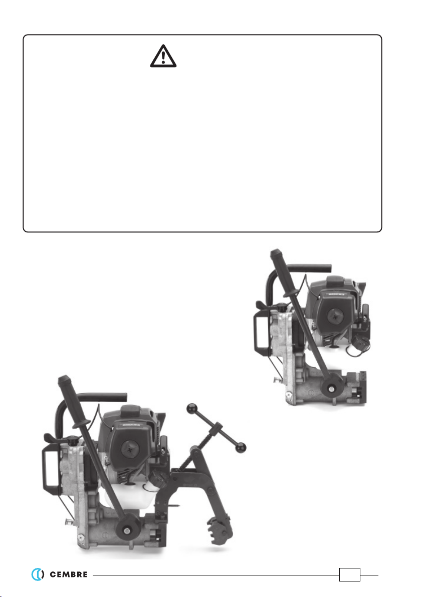
1. GENERAL CHARACTERISTICS
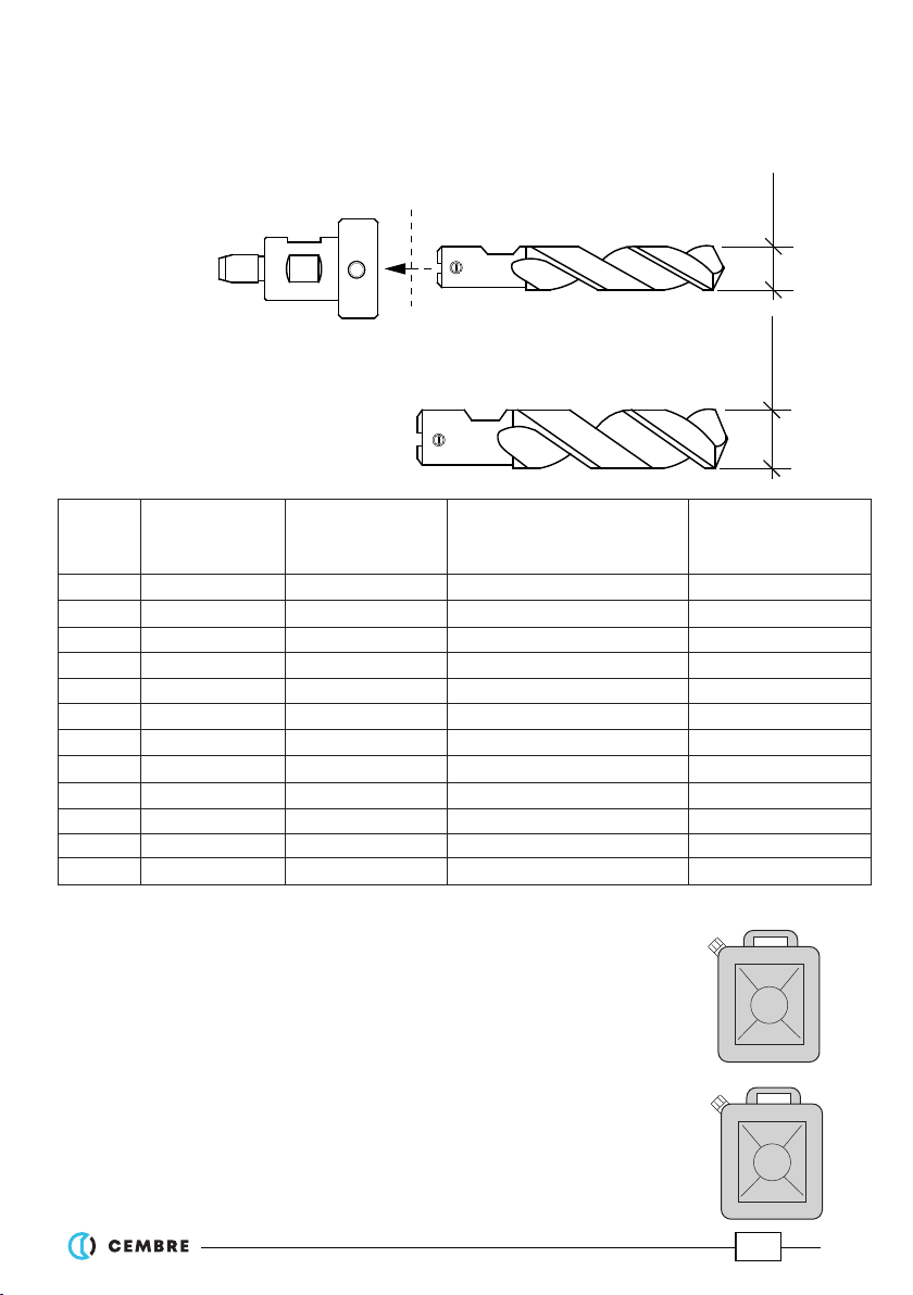
– Drilling capacity:................................................................................................................ 9/32" to 1 9/16"
(with special twist drill bits: hole diameters of 9/32" to 1-1/8" on rails up to 3 1/2" thick)
(with broach cutters: hole diameters of 3/4" to 1-9/16" on rails up to 2 3/4" thick)
– Speed without load:...................................................................................................................... n° 270 rpm
– Combustion engine:
Type:..............................................................Forced air cooled, 2 cycle, horizontal shaft, single cylinder
Model:............................................................................................................................................KAWASAKI TJ45E
Displacement:............................................................................................................................................. 45.4 cm3
Power (SAE J1349):.................................................................................................1.4 kW (1.9 hp) / 7500 rpm
Fuel tank capacity: ...........................................................................................................0.24 US gal (0.9 litres)
Clutch:.............................................................................................. centrifugal with automatic intervention
Starter:..........................................................................................................recoil sarter (with spring damper)
Ignition:..............................................................................................................solid state ignition (C.D.I. type)
Spark plug:............................................................................................................NGK BPMR7A or equivalents
Fuel:................................................................................................. 2% (1:50) oil/gasoline mixture (see § 12)
Fuel consumption: .................................................................................................. 470 g/kW.hr / 350 g/hp.hr
Emissions:................................................... according to "Phase 2" EPA regulation engines class V and
European Directives 97/68/EC, 2001/63/EC and 2002/88/EC
– Weight:.......................................................................................................................................................34.5 lbs
– Weight: with “DBG-Y” clamping device ........................................................................................41.5 lbs
– Gear sump:
Recommended oil:........................... MOBIL SUPER MULTIGRADE 10-30-SAE or
ESSO UNIFARM 10 W 30 or equivalent
–Acoustic noise (Directive 2006/42/EC, annexe 1, point 1.7.4.2 letter u)
– The weighted continuous acoustic pressure level equivalent
A at the work place LpA is equal to............................................................................................. 99.5 dB (A)
– The maximum value of the weighted acoustic displacement
pressure C at the work place LpCPeak is equal to....................................................................116.3 dB (C)
– The acoustic power level emitted by the machine
LWA is equal to..................................................................................................................................107.6 dB (A)
–Risks due to vibration (Directive 2006/42/EC, annexe 1, point 2.2.1.1)
Tests carried out in compliance with the indications contained in EN ISO 5349-1/2 Standard
and under operating conditions much more severe than those normally found, certify that the
weighted root mean square in frequency of the acceleration the upper limbs are exposed is
4.36 m/sec2 max.

4
2. ACCESSORIES SUPPLIED WITH THE DRILL
2.1) Pilot bits for controlling the cooling system:
for use with short broach cutters (7/8 " depth of cut)
– 1 pc PPC 2
for use with long broach cutters (2 " depth of cut)
– 1 pc PPL 2
2.2) Spacer, type DPE, for use with spiral bits and APE adaptor
for controlling the cooling system.
2.3) Adaptor, type ARE, for external cooling, to be used with the
SR5000 cooling unit.
2.4) Grub screw, M8x10
– 4 pcs for clamping cutters or bits onto spindle shaft.
2.5) Socket head cap screws, M6x16
– 4 pcs for securing positioning shoes to front plate.
2.6) Socket head cap screws, M6x25
– 4 pcs for securing special positioning shoes to front plate.
2.7) Range of tools:
– 1 pc 5 mm allen key
– 1 pc 6 mm allen key
– 1 pc 4 mm allen key with handle
– 1 pc spark plug key
– 1 pc brush
2.8) 3.4 fl oz (100 ml) oil bottle
for gear sump.
(Accessories from pos. 2.1 to pos. 2.8 are
included in the “Kit of accessories” having
the code 6001904)
2.9) Type SR5000 cooling unit

5
3. OPTIONAL ACCESSORIES (to be ordered separately)
3.1.1) "DBG-LY" device specific for clamping the drill to the
girder rails (for example 128 GR or GGR 118, Ri60).
With the specific shoes allows the positioning on both sides of
the rails, complete with the TDB 3 termination.
3.1) "DBG-Y" devicewith moving arm for clamping the drill
to the rail web and track fittings, complete with the TDB 6
termination.
This device is supplied with the drill type LD-1PY-ECO
3.1.2) "DBG-GR" device for clamping the drill in correspondance of guard
rail, complete with the TDB 1 termination.
This device is supplied with the drill type LD-1PYGR-ECO.
3.1.3) DBSN device for clamping the drill to flange
rails, for use in conjunction with the MPAF rail shoes.
Using this device the rail drill can remain clamped in
the drilling position even when trains pass over it.
TDB 6
TDB 3
TDB 1

6
3.3) “VAL LD”steel carrying case for accom-
modatingthe completedrillwith theclamping
device.
22 1/2" (L) x 13 1/2" (W) x 17 1/2" (H)
3.5) "MPAU" UNIVERSAL RAIL SHOE for rail or for special
applications such as drilling #20 high speed switch points
(positioning not automatic).
3.5.1) ."MPAU10" UNIVERSAL SHORT RAIL SHOE
forrailorforspecial applications (positioning not automatic).
3.2) "TST 50" two stage template
(to be used with specific DBG-AY clamp)
This device enables the drilling of 150 lb and
aluminium composite contact rails from one side.
Restart of work stroke: 1,97”
Typical application:
– . Aluminium composite rail.
– . 150 lbs contact rail.
3.4) “VALMPA”suitableforstorage ofrailshoes,cutters
and accessories
• 15 1/2” (L) x 13 3/4” (W) x 2 1/4”(H)

7
3.5.2) ."MPAF..." SPECIFIC RAIL SHOES
Suitable for positioning the drill on running and guard rails
Enable the automatic position of the machine onthe drilling axis (H) of
each specific rail.
•Note: Please contact CEMBRE for other types of rail.
RAIL SHOES DRILLING ON GUARD RAILS
RAIL SHOES DRILLING ON RUNNING RAILS
RAIL SHOES DRILLING ON GIRDER RAILS
H
H
(*) to be used with PFA 1 arbour extension and PPL5 Pilot Bit.
100 LB ARA-B 2 1/4”
112/115/119 LB RE 2 5/8”
115 LB-RE-3132 3 1/32”
132 LB RE 3 9/32”
136 LB RE 3 1/4”
MPAF 100 LB ARA-B GR
MPAF 115/119 LB RE GR
MPAF 115 LB-RE-3132
MPAF 132 LB-RE-3932
MPAF 136 LB-RE-314
RAIL SHOE
(Using DBG-GR clamp)
TYPE OF
RAIL
H
inches
128/149 LB 3”
128/149 LB 2 3/4”
149 LB 2 3/4”
GGR 118 2 3/8”
RI60/RI60N 2.87”
NP4A/NP4AM 2.87”
180-105 LB 2.87”
MPAF 128/149 LB GR
MPAF 128/149 LB GR 234
MPAF 149 LB GR 234
MPAF GGR 118
MPAF RI 60 N
MPAF NP4AM
MPAF BA9101
TYPE OF
RAIL
H
inches
RAIL SHOE
(Using DBG-LY clamp
and 2” depth cutters)
40 LB ASCE 3 1/16"
60 LB ASCE 3 1/16"
80 LB ASCE 2 3/16”
85 LB ASCE 2 17/64”
85 LB PRR 2 1/16”
85 LB PS 2 15/64”
90 LB ARA-A 2 9/16”
90 LB ASCE 2 45/128”
100 LB ARA-A 2 3/4”
100 LB ARA-B 2 65/128”
100 LB ASCE 2 65/128”
100 LB DY 2 5/8”
100 LB NYNH&H 2 39/64”
100 LB RE 2 45/64”
100 LB RE-HF 2 45/64”
100 LB PRR 2 9/32”
100 LB PS 2 31/64”
105 LB DY/110 LB RE
2 43/64”
112/115/119 LB RE 2 7/8”
122 CB 2 7/8”
127 LB DY 3 1/8”
130 LB RE/HF-A 2 3/4”
130 LB RE-HF 3 1/16"
130 LB HF-B 3 3/8”
130 LB PS 2 3/4”
131 LB RE 3 1/2”
132 LB RE 3 3/32”
133 LB RE 3”
136 LB RE 3 3/32”
136 LB LE VAL 3 1/16”
140 LB RE/140 PS
3”
141 LB AB/ 141 LB RE
3 3/32”
152 LB PS 3 3/4”
155 LB PS rail 3 3/8”
MPAF 40 LB ASCE
MPAF 60 LB ASCE
MPAF 80 LB ASCE
MPAF 85 LB ASCE
MPAF 85 LB PRR
MPAF 85 LB PS
MPAF 90 LB ARA-A
MPAF 90 LB ASCE
MPAF 100 LB ARA-A
MPAF 100 LB ARA-B
MPAF 100 LB ASCE
MPAF 100 LB DY
MPAF 100 LB NH
MPAF 100 LB RE
MPAF 100 LB RE-HF
MPAF 100 LB PRR
MPAF 100 LB PS
MPAF 105 LB DY
MPAF 115/119 LB RE
MPAF 122 CB
MPAF 127 LB DYM
MPAF 130 LB RE
MPAF 130 LB RE-HF
MPAF 130 LB HF-B
MPAF 130 LB PS
MPAF 131 LB RE
MPAF 132 LB RE
MPAF 133 LB RE
MPAF 136 LB RE
MPAF 136 LB LVM
MPAF 140 LB RE
MPAF 141 LB AB
MPAF 152 LB PS *
MPAF 155 LB PS *
TYPE OF
RAIL
H
inches
RAIL
SHOE

8
3.6) JOINT BAR POSITIONING GAUGES
Positioning gauges MRF-Y... for drilling joint bar
holes at pre-defined distances between rail end
and holes center lines.
POSITIONING
GAUGE A B C
MRF Y10
MRF Y11
MRF Y12
MRF Y13
MRF Y14
MRF Y15
MRF Y16C
MRF Y10: suitable for drilling the following rails 100 ARA-B, 115 and 119 LB RE
MRF Y11: suitable for drilling the following rails 100 ARA-B, 105 DL&W
MRF Y12: suitable for drilling the following rails 115, 119, 132, 136, 140 LB RE, 130 and 155 PS
MRF Y13: suitable for drilling the following rails 80, 90 LB ASCE and 100 ARA-A
MRF Y14: suitable for drilling the 85 LB ASCE rail
MRF Y15: suitable for drilling the 130 LB RE and 136 LE.VAL rails
MRF Y: universal positioning gauge for all rail sizes
•Note: other positioning gauge sizes available upon request.
HOLES DISTANCES
A
C
R
B
2 21/32" 7 1/4" 5 1/2"
3 1/2" 6" 6"
2 21/32" 7 1/4" 5 1/2"
3 1/2" 4 3/4" 4 3/4"
2 23/32" 6" 7"
3 1/2" 6" 6"
3" 6" -
2 7/16" 5" -
2 7/16" 7" -
2 3/8" 7" -
2 3/4" 6 3/4" 6 3/4"
2 11/16" 5 1/2" 5 1/2"
3 1/2" 6" 6"
UG
ES
ng
j
oint
b
ar
e
en rail en
d
RA
IL
END

9
Allthebroachcuttersallowautomaticcoolingby means of the SR5000 unit supplied with the drills.
3.7) BROACH CUTTERS
These cutters rapidly produce high quality, accurate holes
in a single pass.The automatic lubrocooling system reduc-
es friction and eliminates heat build up during the drilling
operation. Under standard conditions a broach cutter can
drill 40-50 holes, depending on the hardness of the rail.
15128
15130
15132
15234
TSC 1 1/8"
15138
TSC 1 1/4"
TSC 1 5/16"
15144
15146
TSC 1 1/2"
TSC 3/4"
01354
01355
01356
01357
01358
01359
01360
01361
01362
01363
01364
12218
3-12224
3-12226
3-12228
3-12230
3-12232
3-12236
BROACH
CUTTER
PILOT
BIT
HOLE
DIAMETER
(inches)
7/8"
15/16"
1"
1 1/16"
1 1/8"
1 3/16"
1 1/4"
1 5/16"
1 3/8"
1 7/16"
1 1/2"
3/4"
7/8"
15/16“
1“
1 1/16"
1 1/8"
1 3/16“
1 1/4"
1 5/16“
1 3/8"
1 7/16"
1 1/2"
9/16"
3/4"
13/16"
7/8"
15/16"
1"
1 1/8"
MAX.
DEPTH OF CUT
(inches)
Ref. PPC 2
Ref. PPL 2
3-10528
2 "
7/8 "
3 "

10
with adapter
3.8) SPECIAL SPIRAL TWIST BITS
Using these bits guarantees optimum performance during the drilling operations. As a
rule, under normal conditions, a spiral bit can drill 70-100 holes, depending on the hardness
of the rail.
For tools of other types, check the dimensional compatibility (particularly the size of the attachment and the length).
APED...
Diam.
3.9) "LR 2" LUBROCOOLER CONCENTRATE, 1 or 5 gallons for optimum
operation of both the broach cutters and the spiral bits.
This product of vegetable origin, to be watered down in the percentage
95% water, 5% oil, will provide a white colour mixture very effective for the
drilling operations resulting in no heating at the rail or the drilling machines.
3.10)"LR 3" ANTIFREEZE CONCENTRATE of 1 or 5 gallons added to the lu-
brocooling mixture with the right percentage will maintain the lubrocooling
mixture fluid in negative temperature consitions.
LR 3
LR 2
PE70
PE95 C
PE130
PE160
PE190
PE220
PE130L-AR
PE3/4”-L1-AR
PE7/8”-L1-AR
PE1”-L1-AR
PE1-1/8”-L1-AR
PE1-1/4”-L1-AR
SPIRAL
BIT ADAPTER
HOLE
DIAMETER
(inches)
9/32”
3/8”
1/2”
5/8”
3/4”
7/8”
1/2”
3/4”
7/8”
1”
1 1/8”
1 1/4”
SPACER
APED70
APED 3/8 Y
APED 130
APED135/165
without adapter
without adapter
APED 130
without adapter
without adapter
without adapter
without adapter
without adapter
included in the APED 70
included in the APED 3/8 Y
included in the APED 130
included in the APED
135/165
DPE
DPE
included in the APED 130
DPE
DPE
DPE
DPE
not required
not required
not required
not required
not required
not required
TST50 + DBG-AY
TST50 + DBG-AY
TST50 + DBG-AY
TST50 + DBG-AY
TST50 + DBG-AY
TST50 + DBG-AY
ADDITIONAL
ACCESSORIES
without adapter
Diam.

11
FIG. 3 – COOLING UNIT
Detail of the
max pressure valve
17 – Vent valve
35 – Attachment
01 – Tank complete with tube
and max. pressure valve
02 – Tap
03 – Quick-coupling
01
02
17
35
03
The type SR5000 coolant unit consists of a tank complete with tube and maximum pressure
valve (01), fitted with a pump device for pressurisation, which must be connected to the attach-
ment (35) on the drill by means of its quick-coupling (03).
The delivery and shut-off of the lubrocoolant are controlled automatically, when drilling
with a broach cutter, by the guide bit; when drilling with a spiral bit, delivery and
shut-off of the fluid must be effected manually by operating the tap (02). The use of
the lubrocoolant supplied by CEMBRE, in the recommended concentrations, guarantees
optimum use of the drilling tools.
Consumption of the lubrocoolant depends both on the variable degree of opening
of the tap (02) and the inner pressure of the tank: it is therefore advisable to open
the tap a little when the tank is at maximum pressure, while it must be fully opened
when the pressure in the tank is low.
When using the coolant system, pay careful attention to the instructions on the tank label.
Warning:
When the tank is not under pressure, check that the bush on the maximum pressure valve is
screwed right down.
To fill tank with lubrocoolant, turn handle anticlockwise approximately 2 turns to release
handle locking mechanism. Remove handle/piston assembly from tank.
4. TYPE SR5000 COOLANT UNIT (Ref. to Fig. 3)

12
ARE adaptor
FIG. 5 – ARE ADAPTOR
FIG. 4
The drill is equipped with a coolant attachment valve (35) and a vent valve (17)
which are located as shown (Fig. 3).
If under certain operating circumstances they need to be interchanged, proceed
as follows:
– Using a 17 mm hexagonal spanner unscrew the vent valve from its seat.
– Using the 4 mm allen key provided with the drill, remove the appropriate coolant valve
from its seat and fit into the vent valve seat.
– Fit the vent valve into the into the vacant coolant valve seat.
When temperatures fall below 32° F (0° C)
the lubrocoolant may freeze which could
cause damage to the seals contained in
the drill coolant system.
It is therefore advisable, when storing
the drilling machine, to empty the
lubrocoolant system completely.
Proceed as follows (Fig. 4):
– Disconnect the quick coupling (03)
from the coolant attachment (35) on
the drilling machine.
– Tilt the machine so that the coolant
attachment is at its lowest point - allowing
for natural drainage.
– Operate the advancing lever (36) to advance
and retract the drilling spindle.
– Gently shake the machine to expel all fluid.
4.1) ARE adaptor
For use with type SR5000 coolant unit. The ARE adaptor is inserted in the quick-coupling of the
tank tube (ref. to Fig. 5), it may be used to provide manual external cooling when cutters are
used to enlarge existing holes, or when using spiral bits not designed for automatic cooling.
If necessary the ARE adaptor can also be used to clean various parts of the drill, by means of the
lubrocoolant pressure jet, e.g. parts such as the tool clamping seat in the spindle shaft, seats
for the fixing screws, etc.

13
5. SPINDLE ADVANCE LEVER (Ref. to Fig. 6)
FIG. 6
The spindle is advanced by moving the lever
(36) (See Fig. 6 a). The lever is fitted with a re-
lease pawl (39) which, when pressed, renders it
independent of the hub and hence the spindle;
the operator can therefore easily vary the an-
gular position of the lever without movement
of the spindle (Fig.6).
FIG. 7
5.1) Adjustment of the advance lever
The movement of the lever must never be
loose, for adjustment proceed to tighten it
by loading the cup springs by means of the
associated self-locking nut, after removing
the protective cap (see Fig. 7).
6b - With the release pawl (39) pressed, the lever is
released from its hub and can repeat the previ-
ous travel without the spindle moving.
6c - With the hub released, moving the lever
towards the operator causes a corre-
sponding advance of the spindle.
6a - Moving the lever (36) towards the operator;
corresponding advance of the spindle.

14
6.1) Assembling broach cutters (Ref. to Figs. 8-11).
6.1.1) Insert the pilot bit in the cutter from the side of the spigot.
6.1.2) Using the lever (36), position the spindle shaft (07) so that both grub screws (18)
become accessible and sufficient space is provided to insert the cutter; if necessary
rotate the spindle shaft manually and sufficiently by inserting the 4 mm male hexagon
key in the appropriate intermediate gear housing (33) in the crankcase of the drill
(see Fig. 11).
6.1.3) Insert the cutter in the spindle shaft so that the two engaging dogs on the cutter
spigot line up with the grub screws (18).
6.1.4) Clamp the cutter by fully tightening the grub screws by means of the 4 mm allen key.
6.1.5) Check that the guide bit slides freely by applying slight pressure on it.
FIG. 8 – ASSEMBLING BROACH CUTTERS
6.2) Assembling special spiral bits (Ref. to Figs. 9 - 11)
6.2.1) Using the advance lever, position the spindle shaft so that both grub screws become
accessible and sufficient space is provided to insert the spiral bit; if necessary rotate
the spindle shaft manually and sufficiently by inserting the 4 mm male hexagon key
in the appropriate intermediate gear housing (33) in the crank-case of the drill cor-
responding to the feed handle (see Fig. 11).
Short type broach cutter
7/8" dept of cut
Pilot bit PPC 2
Long type broach cutter
2" dept of cut
Pilot bit PPL 2
Engaging dogs
07
18
6. PREPARING THE DRILL

15
07
18
DPE *
DPE
Bits PE ...
(e.g. PE 70)
Bits PE ... (e.g. PE 220)
FIG. 11 – MANUAL SPINDLE
ROTATION
FIG. 9 – ASSEMBLING THE SPIRAL TWIST BITS
FIG.10 – ASSEMBLING THE
BIT-SPACER UNIT
APE ...
* use only for APE..., do not required for APED...
33
71
6.2.2) Insert into the spindle shaft, the DPE spacer required to activate the coolant system.
If it necessary to use an APE... adaptor, the bit must first be fitted into the corre-
sponding APE adaptor and locked with the appropriate grub screw, then the DPE
spacer inserted.
Note: Adaptors type APED… (e.g. APED 3/8Y) do not require use of DPE spacer.
6.2.3) Insert the bit-spacer unit in the spindle shaft so that the two engaging dogs on the
bit spigot line up with the grub screws. Press the bit-spacer unit home against
the inner seat of the spindle: this will enable the DPE spacer to open the
coolant circuit (see Fig. 10).
6.2.4) Clamp the bit by fully tightening the two grub screws (18) using the 4 mm male allen
key.

16
7. DRILL TYPE LD-1PY-ECO
The reference LD-1PY-ECO relates to the entire LD-1PNY-ECO drill complete with the clamping
device DBG-Y for clamping it to the rail web and the track fittings (Ref. to Fig. 12).
The DBG-Y device consists of:
– Clamping unit.
– Type TDB 6 termination.
– Socket head cap screws M 8x25 (2 pcs).
– Spring washers (4 pcs).
– Reference pin.
FIG. 12 – DRILL LD-1PY-ECO
reference
pin
TDB 6
M 8x25 screws
and spring washers

17
7.2) Assembly of the DBG-Y clamping device on the drill
The DBG-Y clamping device is fitted to the front plate of the drill, centred by means of the refer-
ence pin supplied and secured with the two socket head cap screws M 8x25 (35) also supplied.
The assembly is illustrated in Fig. 14.
FIG. 13 – ASSEMBLY OF THE TERMINATION
7.1) Assembling of the termination of the DBG-Y device with moving arm for clamping
the drill to the rail web and track fittings.
The termination TDB 6 of the DBG-Y device, with moving arm, have been designed for
adaptation to the different operating conditions on the rails and track fittings; their assembly
is shown in Fig. 13.
• When disassembling the TD termination ensure that, after removing the pivot, the
complete assembly is slid away downward without acting on the holding plate.
holding plate

18
7.3) Assembly of the positioning shoes (Ref. to Fig. 15)
7.3.1) The type MPAF.. and MPAU positioning shoes are secured to the front plate (04)
of the drill by means of the two socket head cap screws M 6x16 supplied.
FIG. 14 – ASSEMBLY OF THE
TYPE “DBG-Y” CLAMP
DBG-Y Clamp
Rail drill front plate
35
reference pin
04
FIG. 15 – ASSEMBLY OF THE POSITIONING SHOES
2 screws M6x16
MPAF...
MPAU

19
FIG. 16 – POSITIONING OF THE DRILL
7.4) Clamping to the rail web (Ref. to Fig. 16)
The special shape of the positioning shoes, each corresponding to the type of rail, enables
the drill to be positioned quickly, accurately and safely on the element to be drilled.
To position the drill, complete with the clamping termination (§ 7.1) and the positioning
template (§ 7.3) suitable for the type of rail to be drilled, proceed as follows:
7.4.1) Withdraw the spindle shaft (07) completely by means of the lever (36).
7.4.2) Bring the moving arm (03) of the clamping device into the fully open position by
means of the handwheel (11).
7.4.3) Place the drill on the rail at the point where the drilling is to be carried out, and
clamp it by tightening the handwheel (11) right down: the positioning shoe will
automatically position the cutter or spiral bit in line with the desired axis; if accurate
positioning relative to the longitudinal axis of the rail is required, use the reference
pin (18).
36
11
03
07
18

20
FIG. 17 – DRILLING
N.B.: switch on the cooling system before starting the drill (§ 4)
8.1) Drill fitted with “short” type broach cutter (depth of cut 7/8").
The drilling sequence may be started with the drill fitted with the broach cutter (§ 6.1),
positioning jig (§ 7.2), the drill being clamped to the rail (§ 7.3), as follows:
8.1.1) Connect the female quick-coupling of the SR5000 cooling system to male coupling
(35) on the drill.
8.1.2) Open the tap (02) fitted on the tank tube.
8.1.3) Using the lever (36) bring the guide bit almost in contact with the rail (Fig. 17a);
keeping the release pawl (39) pressed, release the lever from its cup and return it
to the initial position (Fig. 17b), which will enable the travel of the lever (36) to be
used in the most advantageous way.
36
39
8. DRILLING (Ref. to Figs. 17-18)
Fig. 17b
Fig. 17a
Fig. 17c
This manual suits for next models
1
Table of contents
Other Cembre Drill manuals

Cembre
Cembre SD-15P-ECO User manual

Cembre
Cembre LD-16B Manual

Cembre
Cembre SD-9P-ECO User manual

Cembre
Cembre LD-41P User manual

Cembre
Cembre LD-1P-ECO User manual

Cembre
Cembre SD-15P-ECO User manual

Cembre
Cembre SD-19BR User manual

Cembre
Cembre SD-10E User manual

Cembre
Cembre LD-41P User manual

Cembre
Cembre LD-16B-RP User manual
Popular Drill manuals by other brands

BGS technic
BGS technic 8852 instruction manual

Bosch
Bosch Professional GBH 2-26 E Original instructions

Hitachi
Hitachi DS 13DV2 Instruction manual and safety instructions

Stanley
Stanley SDH550 Original instructions

DeWalt
DeWalt DC727KA user manual

Jet
Jet JMD-45VSPF Operating instructions and parts manual