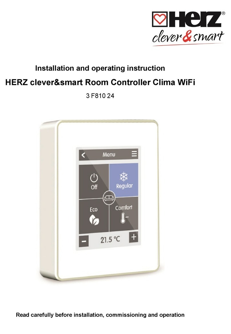
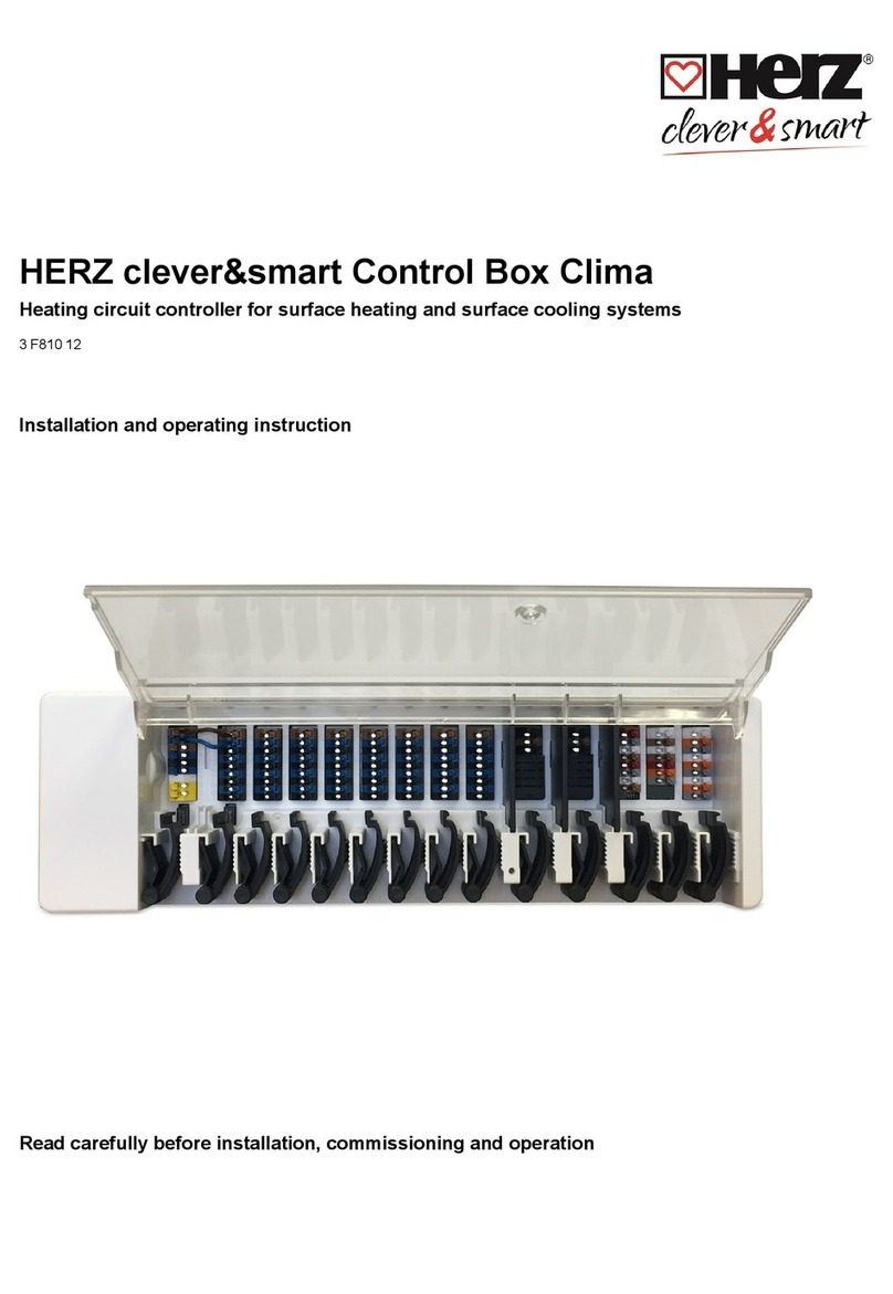
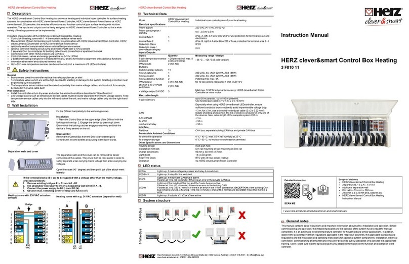
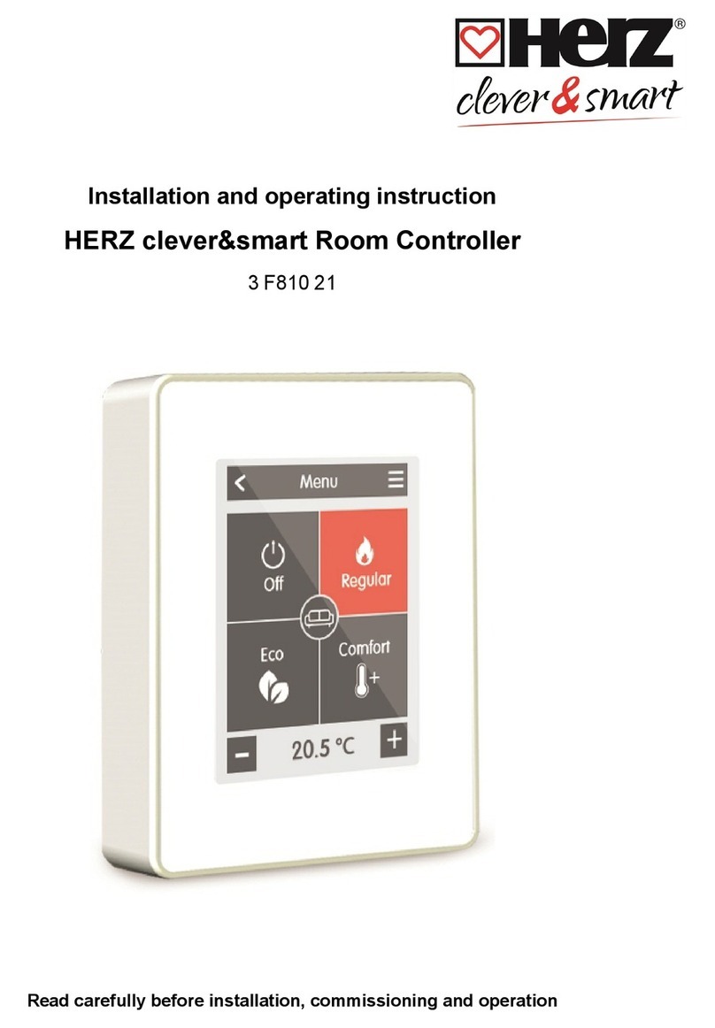
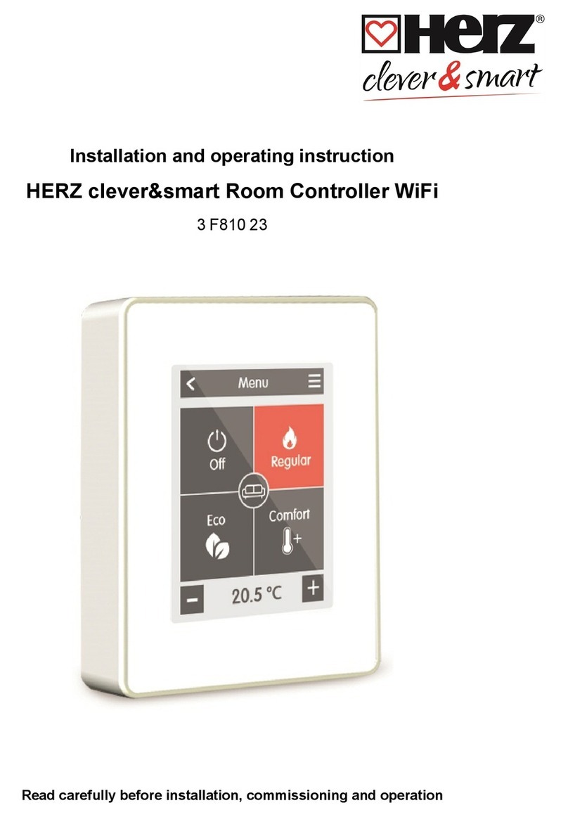
Herz clever&smart Control Box Heating User guide

HERZ clever&smart Control Box Heating
Heating circuit controller for surface heating systems
3 F810 11
Installation and operating instruction
Read carefully before installation, commissioning and operation

CONTENT
Safety Instructions 3
EU-Conformity 3
General Instructions 3
Explanation of Symbols 3
Changes to the Unit 4
Warranty and Liability 4
Disposal and Pollutants 4
Description HERZ clever&smart Control Box Heating 4
Description 4
Technical Data 5
Scope of Supply 6
Installation 6
Wall Installation 6
Electrical Connection 7
Electrical Terminals 8
LED status 9
Wiring structures 10
CAN bus 10
1-Wire-Bus 10
Connection examples HERZ clever&smart Room Controller 11
Connection example single-family house with >8 zones 12
Connection example apartment building 13
Connection Examples 1-Wire Sensors 14
Connection example HERZ clever&smart LEDcontroller 15
1-Wire ID overview 16
Setup Wizard 17
Operation 18
Room Overview 18
Operating Mode 19
Menu 19
Set Operation Hours 20
Expert Menu 21
Settings 22
Devices 23
Rooms 24
Temperature 25
Functions Control Box 26
Zones 32
Example zone setting 33
WiFi 34
Access Point 36
WiFi Sensor 36
Integrating devices without WiFi 37
Service Values 38
Connecting HERZ clever&smart App to the HERZ clever&smart Room Controller WiFi 38
Tips 39
Support 39
2

Safety Instructions
EU-Conformity
By affixing the CE mark to the unit the manufacturer declares that the HERZ clever&smart Control Box Heating conforms to the following
relevant safety regulations
lEU low voltage directive 2014/35/EU
lEU electromagnetic compatibility directive 2014/30/EU
lEU RoHS Directive 2011/65/EU
lEU WEEE Directive 2012/19/EU (Reg.nr. DE 23479719)
conforms. Conformity has been verified and the corresponding documentation and the EU declaration of conformity are kept on file by the
manufacturer.
General Instructions
Please read carefully!
These installation and operating instructions contain basic instructions and important information regarding safety, installation,
commissioning, maintenance and the optimal use of the unit. Therefore these instructions must be read and understood completely by the
installation technician/specialist and by the system user before installation, commissioning and operation of the unit.
This unit is a universal heating and individual room controller for surface heating systems and similar applications. Install the unit only in
dry areas and under the ambient conditions described in “Specifications”.
The valid accident prevention regulations, VDE regulations, the regulations of the local power utility, the applicable DIN-EN standards and
the installation and operating instruction of the additional system components must also be observed.
Under no circumstances does the unit replace any safety devices to be provided by the customer!
Installation, electrical connection, commissioning and maintenance of the device may only be carried out by an appropriately trained
specialist. Users: Make sure that the specialist gives you detailed information on the function and operation of the unit. Always keep these
instructions in the vicinity of the unit.
The manufacturer does not take over any liability for damage caused through improper usage or non-compliance of this manual!
Explanation of Symbols
Danger
Failure to observe these instructions may result in life-threatening effects due to electrical voltage.
Danger
Failure to observe these instructions can result in serious damage to health such as scalding or life-threatening injuries.
Caution
Failure to observe these instructions can result in destruction of the unit or the system, or environmental damage.
Caution
Information which is especially importation for the function and optimal use of the unit and the system.
3
HERZ clever&smart Control Box Heating

Changes to the Unit
lChanges, additions to or conversion of the unit are not permitted without written permission from the manufacturer.
lIt is likewise forbidden to install additional components that have not been tested together with the unit.
lIf it becomes clear that safe operation of the unit is no longer possible, for example because of damage to the housing, turn
the Unit off immediately.
lAny parts of the unit or accessories that are not in perfect condition must be exchanged immediately.
lUse only original spare parts and accessories from the manufacturer.
lMarkings made on the unit at the factory must not be altered, removed or made illegible.
lOnly the settings described in these instructions may be set using the Unit.
Changes to the unit can compromise the safety and function of the unit or the entire system.
Warranty and Liability
The unit has been manufactured and tested with regard to high quality and safety requirements. The unit is subject to the statutory
guarantee period of two years from the date of sale. The warranty and liability shall not include, however, any injury to persons or material
damage that is attributable to one or more of the following causes:
lFailure to observe these installation and operating instructions.
lImproper installation, commissioning, maintenance and operation.
lImproperly executed repairs.
lUnauthorised structural changes to the unit.
lUse of the device for other than its intended purpose.
lOperation above or below the limit values listed in the ‚Specifi cations‘ section.
lForce majeure.
Disposal and Pollutants
The unit conforms to the European RoHS 2011/65/EU for the restriction of the use of certain hazardous substances in electrical and
electronic equipment.
Under no circumstances may the device be disposed of with the normal household waste. Dispose of the unit only at
appropriate collection points or ship it back to the seller or manufacturer.
Description HERZ clever&smart Control Box Heating
Description
The HERZ clever&smart Control Box Heating is a universal heating and individual room controller for surface heating systems. In
combination with HERZ clever&smart Room Controller, HERZ clever&smart Room Sensor or HERZ clever&smart LEDcontroller, this
enables efficient use and function control of your surface heating with intuitive operation. The inputs and outputs can be freely assigned
via HERZ clever&smart Room Controller so that a wide variety of heating systems can be implemented.
Important characteristics of the HERZ clever&smart Control Box Heating:
lControl of 8 heating zones with 1 - 4 thermostatic radiator valves each
lRoom temperature detection in conjunction with HERZ clever&smart Room Controller,
HERZ clever&smart LEDcontroller or HERZ clever&smart Room Sensor
lOptionally weather compensated via outdoor temperature sensor
lOptional control of the heating circuit pump and the mixer (PWM or 0-10 V) possible
l2 separate CAN bus interfaces for building network and private floor or apartment network
lConnectable with other HERZ products via CAN-Bus
lControl of mixers, valves and energy generators via 0-10 V / PWM
l2 additional floating changeover contacts (terminals J and K) for flexible assignment
lInnovative strain relief and coloured terminal strip
lUp to 20 1-Wire temperature sensors can be connected (incl. a maximum of 8 LEDcontrollers)
HERZ clever&smart Control Box Heating
4

Technical Data
Model HERZ clever&smart
Control Box Heating
Heating circuit controller for surface heating systems
Temperature controller
class (ErP)
8
Energy efficiency (ErP) 5 %
Standby loss 0,5 W
Request type invertible heat
pump
"On /off" and/or "modulating"
Electrical specifications:
Power Supply 230 VAC (+/- 5 %), 50-60 Hz
Power consumption /
standby
0.5 - 2.5 W/ 0,5 W
Internal fuse 1 1 (Pos A, left) 2 A slow blow 250 V Fuse protection for terminal area A and electronics
Internal fuse 2 1 (Pos B, right) 4 A slow blow 250 V Fuse protection for terminal area B - I
Protection Class IP 20
Protection class / overvoltage category II / II
Inputs Quantity Measuring range / design
1-Wire temperature sensor
powered, 3-wire system
< 20 pieces (incl. max.
8 LEDcontrollers)
- 55 °C ... 125 °C (3 pole version)
PWM inputs 2 (N2, N5)
Outputs
Switching relay outputs 11
Relay heat pump 1 230 VAC, 4 A, (AC1 920 VA, AC3 185W)
Relay actuator 8 230 VAC, 4 A, (AC1 920 VA, AC3 185W)
Relay additional function 2 Potential-free max. 4 A
PWM outputs 3 (N1, N4, N8) for 10 kΩ working resistance 1 kHz, level 10 V
of which 0-10 V / PWM
switchable
2 (N1, N4)
+ Voltage outputs 24VDC 3 Total max. 12 W for external devices e.g. HERZ clever&smart Room Controller or
mixer motor
Interface
Fieldbus 2 x CAN bus (separate building CAN bus and private CAN bus)
Max. Cable Length
1-Wire Sensors Cable length of the total system 100 m, use suitable twisted pair cable
(LIYCY 2 x 2 x 0.75 mm²)
When using HERZ clever&smart LEDcontroller, ensure sufficient conductor cross-
section to avoid impermissible voltage drop, see "Connection example HERZ
clever&smart LEDcontroller" on page 15.
CAN < 3 m; for ≥ 3 m, use a shielded twisted pair cable (2 x 2 x 0.22 mm²). Isolate
shielding and connect it to the protective conductor of only one of the devices. Max.
cable length of the complete system 200 m.
0-10 V / PWM < 3 m
24 VDC < 30 m
mechanical relay < 30 m
Permissible Ambient Conditions
during operation 0 °C - 40 °C, max. 85 % rel. humidity at 25 °C
for transport/storage 0 °C - 60 °C, no moisture condensation permitted
Other Specifications and Dimensions
Housing Design multi-part ABS
Installation Methods DIN rail mounting or wall mounting on DIN rail
Overall dimensions 95 mm x 303 mm x 57 mm
Light diode 14 x LED green
Real Time Clock RTC with 24 hour power reserve
Operation via HERZ clever&smart Room Controller
5
HERZ clever&smart Control Box Heating

Scope of Supply
lHeating circuit controller for surface heating systems HERZ clever&smart Control Box Heating
l2 spare fuses, 1x 2 AT, 1x 4 AT
lAdditional separation wall for use of non-230 VAC actuators
lDIN rail H= 35 mm L= 280 mm 2 screws 3.5 x 35 mm and 2 dowels S6
lHERZ clever&smart Control Box Heating installation and operating instructions
Installation
Wall Installation
Fix the DIN rail horizontally to the wall using screws.
Installation
1. Place the HERZ clever&smart Control Box Heating on the upper edge of
the DIN rail with the locking catch on top.
2 Engage the device by pressing it down. Ensure that the locking catches
engage completely and that the device is firmly seated on the rail.
Disassembly
Remove the HERZ clever&smart Control Box Heating from the DIN rail by
insert-ing two screwdrivers into the eyelets and pulling them downwards.
Separation walls and cover
The separation walls and the cover can be removed for easier connection of
the cables. They must then be reinstalled in order to safely separate areas
carrying mains voltage from areas carrying low voltages.
Open the cover (90° degree) and then pull it out of the side of the attachment.
If the terminal blocks (B-I) are to be supplied with a voltage other than the mains voltage, proceed as follows:
lRemove existing bridges A1 - B1 and A2 - B2
lIt is absolutely necessary to insert a separating wall between A - B.
lConnect the power supply to B1 (L) and B2 (N).
lObserve max. switching power of relay and fuse (4 AT)
Heating zones with 230 VAC actuators (bridge) Heating zones with e.g. 24 VAC actuators (separation wall)
HERZ clever&smart Control Box Heating
6

Electrical Connection
Low-voltage cables, such as temperature sensor cables, must be laid separately from mains voltage cables.
Before working on the unit, switch off the power supply and secure it against being switched on again! Check that there is no
power flowing! Electrical connections may only be made by a specialist and in compliance with the applicable regulations. The
unit may not be put into operation if there is visible damage to the housing, e.g. cracks.
An all-pole disconnecting device, e.g. heating emergency switch, must be provided on site in the power supply of the
controller.
The strain reliefs are suitable for flexible cables with a
cable sheath diameter of 5 mm to 8 mm, primarily
using the lower strain relief (as shown). The cables
must be checked for firm placement. Solid, thicker
and thinner cables must always be laid firmly and
must be fixed on the installation side.
Massive wires or cables with special wire end sleeves
can simply be pressed into the terminals. For other
wires, the trowel must first be completely pressed
on with a screwdriver as shown.
Wire ferrules made of brass can be difficult
to clamp due to their asymmetric crimping
shape. In this case, remove the wire ferrule.
The plug-in terminals are also suitable for
flexible cables.
7
HERZ clever&smart Control Box Heating

Electrical Terminals
1 L' ----- L' L' L' L' L' L' L' L' NC NC 24 VDC CAN
high
0-10V/
PWM
2 N' ----- N' N' N' N' N' N' N' N' C C GND CAN low
PWM In
3 L L' L' L' L' L' L' L' L' NO NO CAN
high
CAN
high
GND
4 N N' N' N' N' N' N' N' N' CAN low CAN low 0-10V/
PWM
5L L' L' L' L' L' L' L' L' 24 VDC VDD
PWM In
6 N N' N' N' N' N' N' N' N' GND DQ GND
7 --- L' L' L' L' L' L' L' L' CAN
high
GND 24 VDC
8 PE N' N' N' N' N' N' N' N' CAN low PWM
9 PE L' L' L' L' L' L' L' L' GND
Example Wiring of Terminal Blocks
Mains connection heating circuit pump Actuators for the heating zones
Potential-free switching contacts for additional functions
HERZ clever&smart Room Controller in the private CAN bus
Private CAN bus
For linking devices within a housing unit, such as a single-family
house or a flat. Shares all information with all devices in the same
network, including room names, setpoint temperatures, absences,
etc.
HERZ clever&smart Control Box Heating
8

Building CAN bus and 1-Wire sensors
Building CAN bus
For linking devices across several units, such as flats, offices or
hotel rooms. Only shares information relevant for optimising the
overall system:
- Outdoor temperature
- Energy demand
- Flow temperature
- Season (heating / cooling)
0-10 V /PWM outputs for additional functions
LED status
LED A Lights up if mains voltage is present and relay A is switched
LED B - K Lights up if relay B - K is switched.
LED L Flashes if the private CAN bus is active.
Flashes at 1 Hz (60 x / minute) if there is an error in the private CAN bus.
LED M Lights up when the building CAN bus and the 1-wire bus are active.
Flashes at 1 Hz (60 x / minute) if there is an error in the building CAN bus.
Flashes at 3 Hz (180 x / minute) if there is an error in the 1-wire connection. EXCEPTION: If the building CAN bus
remains unused, a flashing (1 Hz (60 x / minute)) of LED M is normal and does NOT mean that there is a error.
LED N Lights up if outputs V1, V2 or V3 are active.
9
HERZ clever&smart Control Box Heating

Wiring structures
CAN bus
Description Implementation Admissibility
Line Yes, optimal installation with maximum range.
Tree No
Star No
1-Wire-Bus
Description Implementation Admissibility
Line Yes, optimal installation with maximum range.
Tree Possible without guarantee for small systems with short line lengths and few
network participants. Keep stub lines short.
Star Not recommended
HERZ clever&smart Control Box Heating
10

Connection examples HERZ clever&smart Room Controller
Do not combine devices designed for heating only (HERZ clever&smart Room Controller/HERZ clever&smart Control Box
Heating) with devices designed for heating and cooling (HERZ clever&smart Room Controller Clima/HERZ clever&smart
Control Box Clima).
Example 1: Line structure with HERZ clever&smart Control Box Heating as end point
A 120 Ohm terminating resistor must be set between the CAN Low and CAN High connections on the first and last device in
the CAN network.
Example 2: Line structure with HERZ clever&smart Control Box Heating in the middle
A 120 Ohm terminating resistor must be set between the CAN Low and CAN High connections on the first and last device in
the CAN network.
11
HERZ clever&smart Control Box Heating

Connection example single-family house with >8 zones
Example:
Line structure with several HERZ clever&smart Control Box Heating via the private CAN bus (e.g. within a residential unit).
A 120 Ohm terminating resistor must be set between the CAN Low and CAN High connections on the first and last device in
the CAN network.
HERZ clever&smart Control Box Heating
12

Connection example apartment building
Example:
Line structure with several HERZ clever&smart Control Box Heating via the building CAN bus (e.g. across several residential
or commercial units).
Use building CAN bus on terminal block M so that no private data such as room temperatures or holiday mode are shared
across flats.
A 120 Ohm terminating resistor must be set between the CAN Low and CAN High connections on the first and last device in
the CAN network.
13
HERZ clever&smart Control Box Heating

Connection Examples 1-Wire Sensors
When connecting the 1-Wire sensors, please record the 16-digit 1-Wire ID and the location of the sensor for later
commissioning of the system! The 1-Wire ID can be found in the device housing and in the device menu under:
Devices -> HERZ clever&smart Control Box Heating -> Resources -> 1-Wire Sensor.
Example 1:
Line. The installation leads from one sensor to the next. A twisted pair cable is to be used for the connection line
Example 2:
Tree structure. A twisted pair cable is to be used for the connection line
HERZ clever&smart Control Box Heating
14

Connection example HERZ clever&smart LEDcontroller
Example line: The installation leads from one sensor to the next. A twisted pair cable must be used for the connecting cable.
The 1-Wire system must be realised with 3 wires (5 VDC, DQ, GND). The total cable length can thus be up to 100 m. Use a suitable
twisted pair cable and ensure sufficient conductor cross-section, e.g. LIYCY 2 x 2 x 0.75 mm², to avoid impermissible voltage drop at the
HERZ clever&smart LEDcontroller below Umin = 4.5 VDC.
15
HERZ clever&smart Control Box Heating

1-Wire ID overview
HERZ clever&smart Room Sensor can be assigned to rooms in two ways:
1. by means of the "Touch-To-Assign" function (T2A)
A detailed description of this assignment procedure is enclosed with the respective unit.
2. By assigning the HERZ clever&smart Room Sensor via the 1-wire ID (16-digit hexadecimal number)
If this method is selected, it is helpful to note the 1-wire ID of the HERZ clever&smart Room Sensors in connection with the room in which
the respective sensor was installed for later assignment within the scope of the system configuration.
The 1-Wire ID can be found inside the sensor on the type plate (1) and on
the supplied sticker (2). We recommend placing the sticker in the following
table.
(1)
(2)
HERZ clever&smart LEDcontroller
HERZ clever&smart Room Sensor
HERZ clever&smart Contact Sensor
HERZ clever&smart Immersion Sensor
HERZ clever&smart Outdoor Sensor
Location 1-Wire ID Location 1-Wire ID
Example Bathroom 1053f67c0308009e 11
1 12
2 13
3 14
4 15
5 16
HERZ clever&smart Control Box Heating
16

6 17
7 18
8 19
9 20
10 21
Setup Wizard
The setup wizard in the HERZ clever&smart Room Controller starts automatically when the device is commissioned for the first time and
guides you through the necessary basic settings in the correct sequence. Press the arrow keys in the upper right/left corner to return to the
next or previous setting.
Commissioning must also be completed on all other HERZ clever&smart Room Controller in the network.
The HERZ clever&smart Control Box Heating is usually configured using a HERZ clever&smart Room Controller. If the
"configurator" of the HERZ clever&smart Control Box Heating is a HERZ clever&smart Room Controller WiFi with an existing
internet connection, a configuration can also be continued or changed using the HERZ clever&smart App.
The setup wizard is restarted via the "Factory settings" menu item.
17
HERZ clever&smart Control Box Heating

Operation
To parameterise the HERZ clever&smart Control Box Heating, you need at least one HERZ clever&smart Room Controller. This is
connected to the HERZ clever&smart Control Box Heating via the private CAN bus as described above (see "Electrical Connection" on
page 7).
Room Overview
After activating the start screen, displays the room temperature of the configured rooms and, if a 1-wire outdoor temperature sensor is
connected, also its temperature.
Room icon
By selecting a room icon, you are
forwarded to the room temperature
settings.
Multiroom selection
By dragging your finger
vertically across several rooms, you
can change the operating mode in all
rooms at the same time.
°C Room
temperature
Current room temperature
18

Operating Mode
Overview > Operating Mode
Back/ Forward
Navigation back to overview
Room
Display of the selected room
Reference
temperature
Setting the setpoint temperature for
the active operating mode in the
displayed room
Menu
Navigation to the main menu
Operating Modes
The operating mode shown in colour is
currently active and can be changed by
selecting another mode. Manually selected
modes remain active until the next change
of mode by the timer program. A
background frost protection function
remains active in the "off" mode.
Menu
Overview > Operating Mode > Menu
Holiday
Set time period and temperature for a
longer absence
Timer
Setting of individual heating or cooling
times for each day of the week with
copy function for subsequent days
Expert
Further settings for the specialist
19
HERZ clever&smart Control Box Heating

Set Operation Hours
Overview > Operating Mode > Menu > Timer
Setting of individual heating and cooling times for the selected room.
Operating Modes
Selection of the operating mode to
select individual heating sections.
Clock
Time table of the selection in periods
of 30 minutes increments. Touch
individual segments, or drag your
finger over complete time intervals to
colour them according to the selected
operation mode.
Menu
Opens the copy function. This function
allows you to copy the heating times for
the next day, on Monday-Friday or
Monday-Sunday.
Back / Next
Weekday Selection of the day of the week
to be set
Set Operation Hours
Step 1
Use the arrow keys to select the
desired day.
Step 2
Select the desired mode (Normal,
Comfort, Eco or Off) and then move
your index finger over the desired
time period. The selected period
changes colour to the colour of the
selected operating mode after
selection. Set the times of the other
operating modes in the same way.
Step 3
After completing the setting of the
individual heating or cooling times,
you have the option of copying the
times via the main menu to the
following day on Monday - Friday or
to Monday - Sunday or to set them
individually for each day of the
week.
In the interests of efficient and energy-saving single room
control, the operating times should be set specifically for
each room.
When setting the operating times, please consider that
surface heating systems are inherently inert.
HERZ clever&smart Control Box Heating
20
Other manuals for clever&smart Control Box Heating
1
This manual suits for next models
1
Table of contents
Other Herz Controllers manuals

Herz
Herz clever&smart Room Controller User guide

Herz
Herz clever&smart Room Controller Clima WiFi User guide

Herz
Herz clever&smart Control Box Heating User manual

Herz
Herz F 7713 01 User manual

Herz
Herz clever&smart Room Controller WiFi User guide

Herz
Herz clever&smart Control Box Clima User manual

Herz
Herz clever&smart Control Box Clima User guide

Herz
Herz 7708 Series User manual