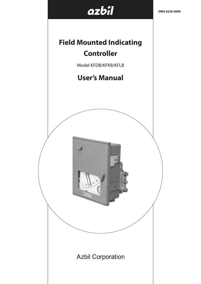
Azbil KFPA User manual

Field Mount type Pressure
(Temperature) Indicating Controller
Model KFPA/KFTA
User’s Manual
OM2-6110-0100

Copyright, Notices and Trademarks
© 1998-2020 Azbil Corporation All Rights Reserved.
While this information is presented in good faith and believed to be
accurate, Azbil Corporation disclaims the implied warranties of
merchantability and fitness for a particular purpose and makes no
express warranties except as may be stated in its written agreement
with and for its customer.
In no event shall Azbil Corporation be liable to anyone for any indirect,
special or consequential damages. This information and specifications
in this document are subject to change without notice.

Model KFPA, KFTA - Field Mount type Pressure Indicating Controllers i
Safety
Safety instructions
Preface
Correct installation and periodic maintenance are essential to the safe use of your
differential pressure transmitters.
Read the safety instructions provided in this manual carefully and understand them
fully before starting installation, operation, and maintenance work.
Inspection
On delivery, make sure that the specifications are correct and check for any damage
that may have occurred during transportation. This equipment was tested under a strict
quality control program before shipment. If you find any problem in the quality
specifications, please contact an Azbil Corp. representative immediately, providing the
model name and serial number.
The name plate is mounted on the top of the enclosure.
Precautions
The following symbols are used in this manual to ensure user safety.
WARNING
Denotes a potentially hazardous situation which, if not avoided, could result in
death or serious injury.
CAUTION
Denotes a potentially hazardous situation which, if not avoided, could result in
operator minor injury or damage to device.

Safety Azbil Corporation
ii Model KFPA, KFTA - Field Mount type Pressure Indicating Controllers
Safety messages
Installation
Maintenance
WARNING
• When installing the transmitter, ensure that the transmitters gaskets do not
protrude from the process connection parts, such as flanges contacting the
process pipes.
• Never use the transmitter in applications that are outside the rated pressure or
temperature range. Always observe connection specifications. Damage to the
transmitter, or leakage, may endanger plant, equipment or human safety.
CAUTION
• After installation, do not step on the transmitter as this may damage it, or cause
physical injury.
• The glass indicator may break if hit with a tool or other object, and cause
physical injury.
• This transmitter is heavy. During installation, please ensure that your footing is
safe, and always wear safety shoes.
WARNING
• Before disconnecting the transmitter from the process for any reason including
maintenance, wait for safe levels in residual pressure, fluid or gas. Extreme
caution should be taken to avoid fluid eruption.
• Prevent burns. Check venting or draining direction, and keep plant personnel out
of the way of vented gas or drained fluid.
CAUTION
Strict product controls were exercised during the manufacture of this transmitter.
Never modify the transmitter in any way. In-plant modifications may result in
damage to the transmitter or to property and human safety.

Table of Contents
1: Description
1-1: General.............................................................................................................. 1
1-2: Structure ........................................................................................................... 1
1-3: Specifications................................................................................................... 2
1-3-1: Common specifications.............................................................................................. 2
1-3-2: Specifications of pressure element............................................................................ 3
1-3-3: Specifications of temperature element ...................................................................... 3
1-3-4: Specifications of accessories..................................................................................... 4
2: Indicating controller section
2-1: General.............................................................................................................. 5
2-2: Descriptions of mechanisms .......................................................................... 5
2-2-1: Deviation generating mechanism .............................................................................. 5
2-2-2: Control mechanism.................................................................................................... 6
2-2-3: Manual controller unit ................................................................................................ 9
2-2-4: Pneumatic signal receiver unit (set point pointer)...................................................... 10
2-2-5: Batch switch unit ........................................................................................................ 10
3: Installation
3-1: Air piping .......................................................................................................... 11
3-2: Connection method ......................................................................................... 11
3-3: Pressure element............................................................................................. 12
3-4: Temperature element....................................................................................... 13
4: Operation
4-1: Preparations for operation.............................................................................. 15
4-2: Pressure control .............................................................................................. 15
4-2-1: For liquid or gas measurement .................................................................................. 15
4-2-2: For steam measurement............................................................................................ 16
4-3: Manual operation ............................................................................................. 18
4-4: Automatic operation ........................................................................................ 18
4-5: Unusing the rate action................................................................................... 19
4-6: Setting of batch switch.................................................................................... 19
5: Calibration and adjustment
5-1: Deviation generating mechanism................................................................... 20
5-2: Controller mechanism ..................................................................................... 21
5-2-1: Balance adjustment for controller proportional band ................................................. 21
5-2-2: Calibration of reset and rate units.............................................................................. 22
5-2-3: Other calibration and adjustment procedures............................................................ 24
5-3: Adjustment of set point indication................................................................. 28
5-4: Transmitter unit................................................................................................ 29
Table of Contents
5-5: Detecting element ............................................................................................ 30
5-5-1: Pressure element....................................................................................................... 30
5-5-2: Temperature element ................................................................................................ 31
6: Maintenance and troubleshooting
6-1: Routine inspection........................................................................................... 32
6-2: Controller unit .................................................................................................. 33
6-3: Pilot relay.......................................................................................................... 34
6-4: Removing the AUTO unit when in manual operation ................................... 35
6-5: Troubleshooting............................................................................................... 36

Model KFPA, KFTA - Field Mount type Pressure Indicating Controllers 1
Azbil Corporation
1: Description
1-1: General
The field mount type indicating controllers measure and indicate various types of
process variable (PV) and, at the same time, they compare the process variable with
the set point (SP) and generate a pneumatic control output signal of 20 to 100 kPa
{0.2 to 1.0 kgf/cm²}.
Setting of the set point value can be done either in the local mode with the manual
setting knob (this knob is adjustable either inside the casing or from outside of the
casing) or in the remote mode with an external pneumatic signal. These instruments
also can transmit a pneumatic signal of 20 to 100 kPa {0.2 to 1.0 kgf/cm²} which is
corresponding to the measured process value.
The only difference between pressure measuring instruments and temperature
measuring instruments is their sensor element.
1-2: Structure
The KF instrument is comprised of three major units, namely, casing, circuit board on
which various units are mounted, and pressure sensor (or temperature sensor).

Azbil Corporation
2Model KFPA,KFTA - Field Mount type Pressure Indicating Controllers
1-3: Specifications
1-3-1: Common specifications
Indication Accuracy of
indication +1% F.S.
Indicating angle 44°
Scale length 150 mm
Setting Manual setting Inside or outside of the case
External air
pressure setting 20 to 100 kPa {0.2 to 1.0 kgf/cm²}
Control action P + Manual reset, PI, PID
PD + Manual reset,
PID, PI + Batch switch, PID + Batch switch,
P + External reset, PD + External reset, ON-OFF action,
Differential gap operation; Direct or reverse action available for
all actions.
Proportional band 5 to 500%
Integral time 0.05 to 30 min.
Derivative time 0.05 to 30 min.
Differential gap 1 to 100%
Manual reset 20 to 100 kPa {0.2 to 1.0 kgf/cm²} air
pressure setting
Batch switch Set pressure 60 to 110 kPa {0.6 to 1.1
kgf/cm²}
Air pressure
specifications
Supply air pressure 140 + 14 kPa {1.4 + 0.14 kgf/cm²}
Controller output;
20 to 100 kPa {0.2 to 1.0 kgf/cm²}
(Load φ4 × 3 m + 20 c.c.min.} 0 or supply
air pressure (on-off, differential gap)
Connection Rc1/4 (PT1/4) or 1/4NPT, female
Air consumption 4 /min(N) (at 50% equilibrium)
Output air
pressure gauge 0 to 200 kPa {0 to 2 kgf/cm²}, 40 mm
Ambient
temperature range
-30 to 80°C
Ambient
humidity range 10 to 90% RH
Case, door Water proof type Equivalent to JIS F 8001, Class III splash
proof, IEC IP54, NEMA3
Case Aluminium diecasting, dark beige, acryl
baking
Door Glass fiber reinforced polyester resin,
dark beige
Weight Approx. 5.5 kg (for PI indicating controller, excluding the
element)

Azbil Corporation
Model KFPA, KFTA - Field Mount type Pressure Indicating Controllers 3
1-3-2: Specifications of pressure element
1-3-3: Specifications of temperature element
Measuring
range Bellow type -101.3 to 0 kPa {-760 to 0 mmHg}
to 0 to 200 kPa {0 to 2 kgf/cm²}
Spiral bourdon type 0 to 300 kPa {0 to 3 mmHg} to 0 to
35 MPa {0 to 350 kgf/cm²}
Bellows receiving air
pressure type 20 to 100 kPa {0.2 to 1.0 kgf/cm²}
Material SUS316
Bellows receiving air pressure type is phosphorus bronze.
Connection Process G1/4 (RF1/4) female
Pneumatic signal Rc1/4 (PT1/4) or NPT1/4 female
Measuring
range -50°C to +50°C min. ~ 0°C to +500°C max.
Material sealed
Measuring range Material sealed
0 ~ 50
Kerosine0 ~ 100
0 ~ 150
0 ~ 200 Silicon
0 ~ 300
0 ~ 400 N2gas
0 ~ 500
50 ~ 100 Kerosine
100 ~ 200 Silicon
100 ~ 300
100 ~ 400 N2gas
-50 ~ 50 Ethyl alcohol
-50 ~ 100 Silicon
Material for
wetted section
Heat sensitive section SUS304
Protecting tube
SUS316, SUS316L or SUS304
Refer to “3-4: Temperature element” on
page 13 for details
Material for lead and
armored tube SUS304

Azbil Corporation
4Model KFPA,KFTA - Field Mount type Pressure Indicating Controllers
1-3-4: Specifications of accessories
Transmitter
mechanism
Transmitting air
pressure
20 to 100 kPa {0.2 to 1.0 kgf/cm²} (load
φ4 mm ×3 mm + 20 c.c.min.)
Air consumption 4 /min(N)
Manual
operation unit:
Balance-bumpless type
Manual pressure
setting range
10 to 130 kPa {0.1 to 1.3 kgf/cm²}
Air consumption 3 /min(N)
Air set: Pressure regulator valve with filter 40 mm, 0 to 200 kPa {0 to 2
kgf/cm²} pressure gauge
Maximum primary
pressure
970 kPa {10 kgf/cm²}
Air consumption 0.95 /min(N) (at output pressure 140 kPa
{1.4 kgf/cm²})
Protecting tube: Use only for the temperature indicating controller
Flange type JIS 10K, 20K, ANSI 150, 300
Screw-in type R3/4, 1 (PT3/4, 1)

Azbil Corporation
Model KFPA, KFT - Field Mount type Pressure Indicating Controllers 5
2: Indicating controller section
2-1: General
The free end of the sensor element is displaced in proportion to the measured process
value. The displacement is fed through a linkage to the deviation generating
mechanism which magnifies and indicates the deviation on the scale. At the same
time, through another linkage, the control deviation amount is fed to the controller unit
which performs the proportional, reset and rate actions on the deviation amount in
order to produce a pneumatic control output signal.
2-2: Descriptions of mechanisms
2-2-1: Deviation generating mechanism
The deviation generating mechanism consists of a deviation detecting section and an
indicator section. It detects the deviation of the measured value of the process variable
(PV value indicated by the measuring pointer on the scale) from the set point value
(SP value indicated by the set point pointer) and controls the position of the flapper
with respect to the nozzle via a control link.
Figure 1 Figure 2
Deviation
Deviation link
Set point pointer
(green)
Measuring pointer (red)
Link

Azbil Corporation
6Model KFPA,KFT - Field Mount type Pressure Indicating Controllers
2-2-2: Control mechanism
The control mechanism consists of a controller unit, a reset unit, and a rate unit.
Different combinations of these units are possible to attain different control actions.
Controller unit
Displacement of the deviation link is fed via the flapper pin of the feedback link to the
flapper, so that its gap with respect to the nozzle is varied and consequently the nozzle
back pressure is varied. The nozzle back pressure is boosted by the pilot relay and
delivered as the pneumatic output signal of the controller. This output signal is led to
the feedback chamber in order to return the flapper-to-nozzle gap to that existed before
this displacement took place. Ultimately the controller output pressure is balanced at a
value in a certain proportion to the deviation.
Setting of proportional band can be done by turning the proportional band dial which
varies the crossing angle between flapper and deviation link (feedback link).
Figure 3
Proportional band
setting dial
Index
Link length
adjusting screw
Flapper adjusting pin
Stopper pin
Dial stopper
Feedback lin
k
adjusting pin
Feedback room
Reset room

Azbil Corporation
Model KFPA, KFTA - Field Mount type Pressure Indicating Controllers 7
Reset unit (integrating unit)
Pneumatic pressure of the feedback chamber is fed to the reset chamber through
capacity and restriction of the reset unit. Thereby attaining a reset action. When the
rate unit is provided, a derivative action also can be attained. A bellows is provided in
the chamber of the rate unit and part of the controller output pressure is directly led to
this bellows to adjust the amplitude of the derivative action.
Other control operations
(a) On-Off action
The nozzle back pressure is directly applied to the pilot relay.
The control operation is done in an ON-OFF mode in response to the open or
closed state of the nozzle.
(b) Differential gap action
The feedback chamber of the controller unit is replaced with a spring-function
device and the output pressure is led to the reset chamber. The differential gap
width is adjustable as required.
Figure 4 Figure 5
Figure 6
Reset dial
Needle
Rate off switch
Feedback
chamber
Control
pneumatic
pressure
Control
pneumatic
pressure
Reset
chamber
Rate dial
Rate
bellows
Reset unit
Rate unit
SP (Index) SP (Index)
ONON
OFFOFF
Increase Increase
Operational gapOperational gap
INC. MEAS. DEC. OUTINC. MEAS. INC. OUT

Azbil Corporation
8Model KFPA,KFTA - Field Mount type Pressure Indicating Controllers
(c) Additional of manual reset
Such manual reset provisions can be incorporated that the output pressure of the
pilot relay is applied to the feedback chamber of the controller unit and the manual
reset pressure produced by a pressure regulator is applied to the reset chamber.
(d) Addition of external reset
This provision is such that a reset signal as explained in the above item (c) is
applied externally. The external signal can be applied through the RES port of the
customer connection block.
Figure 7
Deviation link
Integral
(reset)
chamber
Feedback
chamber
OUTPUT
Air supply
Pressure
regulator
OUTPUT
Integral
(reset)
chamber
Atmospheric
pressure
Proportional + Manual reset ON/OFF action Differential gap action

Azbil Corporation
Model KFPA, KFTA - Field Mount type Pressure Indicating Controllers 9
2-2-3: Manual controller unit
The manual controller unit consists of a pressure regulator for manual pressure setting
and an AUTO/MAN transfer switch.
When in the automatic mode (the lever is set in the A position), the output air pressure
gauge indicates the automatic control output pressure; when the check button is
pressed, the gauge indicates the regulator output pressure (manual controller output
pressure).
When in the manual mode (the lever is set in the M position), the output pressure of
the regulator is led to the reset chamber of the controller unit and, at the same time, it
is indicated by the output pressure gauge and applied to the control valve for remote
control operation. If the check button is pressed in this case, the pressure gauge
indicates the controller output pressure.
Figure 8 Figure 9 Diagram of manual
controller unit
Balance check button
Auto/manual transfer lever
Loading pressure knob
AM
Check
Button
Output air
pressure gauge
Output
pressure Air supply
Integral
(reset)
chamber
Controller output
Feedback
chamber

Azbil Corporation
10 Model KFPA,KFTA - Field Mount type Pressure Indicating Controllers
2-2-4: Pneumatic signal receiver unit (set point pointer)
This unit receives with its bellows an external pneumatic signal of 20 to 100 kPa {0.2
to 1.0 kgf/cm²} and converts this pneumatic signal into a mechanical position
displacement. This displacement is conveyed via a travel link to the deviation
generating mechanism which magnifies the displacement so that the input signal is
indicated as a set point signal on the indicator scale.
2-2-5: Batch switch unit
When the output has exceeded a preset limit, a relay trips so that the reset pressure
cannot increase above the preset limit. This unit is used to prevent abnormal excursion
of signal when starting operation of a batch process. (This unit is effective only for
control of high limit.)
Preloading for a batch process can be done by applying an external preload pressure to
the connector block (RES port) of the instrument.
Figure 10
Figure 11
Connected to link
Control pneumatic pressure
Reset unit
Atmosphere
(or 20 to 100 kPa
{0.2 to 1.0 kgf/cm2}
preload pressure)

Azbil Corporation
Model KFPA, KFTA - Field Mount type Pressure Indicating Controllers 11
3: Installation
For installation and connections of the instrument, see the drawings of instrument
mounting dimensions.
3-1: Air piping
For piping, use copper pipes of OD 6 mm (ID 4 mm) with brass fittings HI-ZEX tubes.
(HI-ZEX: Tradename of polyethylene tubes manufactured by Mitsui Petrochemical
Ind. Ltd.)
Air supply
(a) The air supply must be clean, dry air of 140 + 14 kPa {1.4 + 0.14 kgf/cm²}.
Connect the air supply to the instrument via a filter and a pressure regulator. When
two or more instruments are used, provide a filter and a regulating valve for each
instrument.
(b) Connect the supply air to the SUP port of the air connection manifold of the
instrument.
~Note Use of pipe sealing agent may be harmful to pipes. If sealing agent is
required, sparingly apply it to the male connector.
Output air
Connect the pipe for the control valve to the OUT port of the air connection manifold
of the instrument.
3-2: Connection method
(1) The air connection ports at the bottom of the instrument casing are as shown
below. Both Rc1/4 (PT1/4) thread and 1/4NPT thread are provided for each
connection item. Seal the unused ones with plugs.
(2) If an air set is provided, connect the air supply to the IN port of the air.
ESP: External SP signal
X: Receiving or transmitting pneumatic signal
OUT: Controller output pressure
RES: External reset signal
SUP: Supply air pressure - When in manual reset external
reset signal connection port is
connected to SUP through a pipe.
Figure 12 Pneumatic piping connection port
Rc1/4 female screw
1/4NPT female screw
ESP X OUT RES SUP

Azbil Corporation
12 Model KFPA,KFTA - Field Mount type Pressure Indicating Controllers
3-3: Pressure element
The connection port (G1/4 (PF1/4), female) for the process pressure piping is located
on the bottom of case.
Proper piping may differ depending on the process condition and the instrument
installation. Generally, attention should be paid to the following points.
(1) Provide a stop valve in the pressure connection tube so as to allow maintenance
operation without interrupting the process.
(2) Provide a cock for drain and air release. In case of a horizontal piping, provide a
gradient of 1/100 or more.
(3) If the process pressure largely pulsates or varies, provide a pulsation preventing
means to smooth out pressure. (Please consult an Azbil Corp. representative on a
special case.)
Figure 13
Shutoff valve
Blow down valve
Stop valve
Process
piping

Azbil Corporation
Model KFPA, KFTA - Field Mount type Pressure Indicating Controllers 13
3-4: Temperature element
The temperature element consists of a heat sensing section, a capillary section and a
displacement converting section. Entire system is compensated for ambient
temperature change.
(1) The capillary and an armored tube covering it shall have a bending radius of 60 mm
over to avoid excessive stress.
(2) Select proper type of the heat sensing element depending on the condition of
measured fluid and the type of process vessel.
(3) To measure temperature of a fluid flowing in a process pipe, locate the heat
sensing section in the center of the pipe and along the fluid flow whenever
possible.
~Note Pay attention to the mounting method and the inserted length of the
sensing bulb (protecting tube) so that no abnormally large force is
applied to it, in case where measured fluid of 400°C or more has higher
viscosity, where flow rate exceeds 3 m/sec., or where Carman’s vortex is
generated.
Figure 14
Sensing bulb Thermal insulation
Mounting boss
Capillary
tubing
Capillary
tubing
Capillary
tubing
Lead pipe Lead pipe
Lead pipe
1 inch or 3/4 inch R(PT) 1 inch or 3/4 inch R(PT)
1 inch JIS 10K - 25 mm flange
φ
6.5
φ
6.5
φ
6.5
(A) Union-connected bulb
(B) Union-connected bulb with well
(C) Flange-connected bulb with well

Azbil Corporation
14 Model KFPA,KFTA - Field Mount type Pressure Indicating Controllers
Temperature
range
(C)
Heat
sensing
section
length
Heat sensing
section
diameter
(d mm)
Protecting
tube diameter
(D mm)
Length
below
screw
(below
flange)
L (mm) Specification
of screw Flange ratings
Min. Max.
0 ~ 50 145
d = 12.7,
D = 17
200
1000
R1 (PT1) or
R3/4(PT3/4)
JIS 10K 25 mm
50 ~ 100
-50 ~ 50 83
100
0 ~ 100
-50 ~ 100 66
0 ~ 150
100 ~ 200 83
0 ~ 200 45
100 ~ 300
0 ~ 300 35
100 ~ 400
260 d = 22,
D = 27 300 R1(PT1) or
1NPT
0 ~ 400 JIS 10K, 20K 40 mm
0 ~ 500 ANSI 150, 300 1½ mm
This manual suits for next models
1
Table of contents
Other Azbil Controllers manuals

Azbil
Azbil RA890G User manual

Azbil
Azbil RA1B User manual

Azbil
Azbil Infilex VC User manual

Azbil
Azbil AB-7352-U User manual

Azbil
Azbil C25 User manual

Azbil
Azbil C15 User manual

Azbil
Azbil KFDB User manual

Azbil
Azbil C15 User manual

Azbil
Azbil Infilex ZM WY5122 User manual

Azbil
Azbil Infilex WY5317C User manual
Popular Controllers manuals by other brands

Thermo Scientific
Thermo Scientific TSB140R Operating and maintenance instructions

Abrams
Abrams Logic 1100 Installation & operation manual

ModelCraft
ModelCraft VR18T Important information

Mitsubishi Electric
Mitsubishi Electric MELSEC FX-1HC user guide

Mitsubishi
Mitsubishi FX3UC Series user manual

Advantage Controls
Advantage Controls MicroTron manual