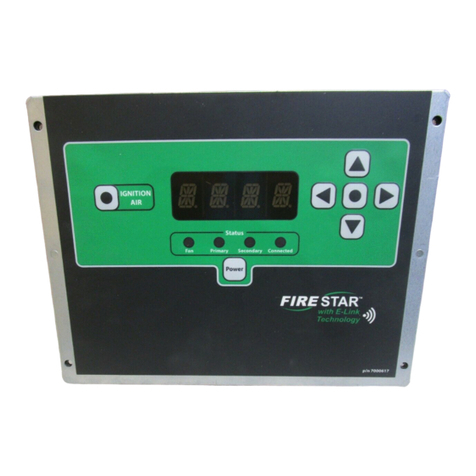
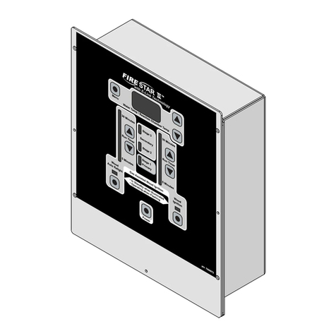
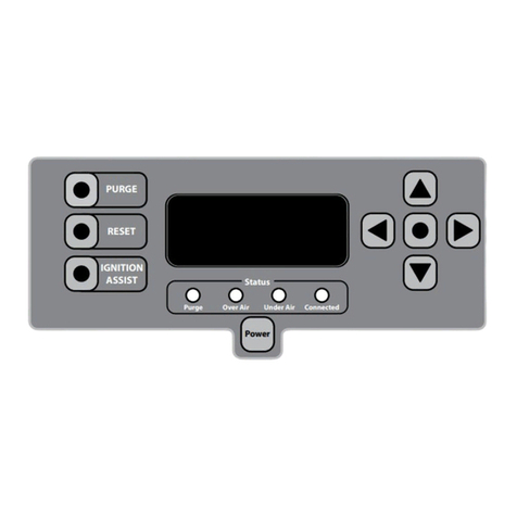
Central Boiler Fire Star XP User manual

with E-Link Technology
™
OWNER’S MANUAL
For Maxim® outdoor furnace models with
compatible FireStar® II controllers.
Take a few minutes to write down information about your home’s
wireless network and your Maxim outdoor furnace.
__________________________________________________________
WIRELESS NETWORK NAME
__________________________________________________________
WIRELESS NETWORK PASSWORD
__________________________________________________________
YOUR OUTDOOR FURNACE SERIAL NUMBER
Save This Manual for Future Reference
27-Jan-2016 • (p/n 9000366) - REV. A
SOFTWARE VERSION R3.0

The FireStar XP Wi-Fi Module is a remote display for the FireStar II
electronic controller. It has the ability to set up its own wi- network
to send and receive data from another wi- enabled device like a
laptop, tablet or smartphone. The FireStar XP can be connected to an
existing wi- network like your home’s, if you have one. If your home
wi- network is connected to the internet and you create an account
at MyFireStar.com, you can take advantage of the FireStar XP’s online
features – features that include real-time status, operational history,
viewing charts and graphs, and receiving alerts.

TABLE OF CONTENTS
Stand Alone Network ..................................1
Connect to Home Wi-Fi Network .......................3
Option A - Set Up Using Laptop or Smartphone .....3
Option B - Connect Using FireStar XP Keypad .......4
Using MyFireStar.com Website .........................6
Dashboard..........................................7
Furnace Settings ....................................9
Account Settings Screen ...........................10
Indoor or Furnace-mounted Display Operation........11
FireStar XP Display Alerts ...........................11
To Display Water Temperature Setpoint.............12
To Unlock/Lock FireStar XP .........................12
Changing Settings With FireStar XP Module ........13
To Display Menu ...................................13
Variables ..............................................14
Wiring Diagrams . . . . . . . . . . . . . . . . . . . . . . . . . . . . . . . . . . . . . . 19
Troubleshooting ......................................21


1
STAND ALONE NETWORK
By default, the FireStar XP will be in Setup/Stand Alone
Network Mode when rst turned on. This mode allows the
FireStar XP to set up its own wireless network without the
need of a wireless router.
1. Power on the FireStar XP. Once the blue LED stops
ashing and remains on, continue with step 2.
2. Using your smartphone, laptop or other wi- device, scan
for available wireless networks.
NOTE: In order for your laptop or other wi- device to see the
FireStar XP, it will have to be within range of the XP module.
3. Select the wireless network that begins with FIRESTAR_
and connect to it. The numbers after the name are unique
to your FireStar XP.
4. Once connected, open your web browser and go to
172.20.50.1, the address for the FireStar XP.
This is where you get a quick glimpse of the current status of
your outdoor furnace and alerts.
Furnace Status
Shows if the outdoor furnace is on or o.

2
Water Temp
Shows the current reading of the outdoor furnace water
temperature in degrees Fahrenheit.
Fire Temp
Shows temperature reading of the burner. Due to limitations
of the temperature sensor, it is not positioned in the hottest
area of the burner. The actual secondary combustion
temperature may be hotter than what is displayed. This
temperature reading is used the by FireStar II controller to
optimize the performance of the outdoor furnace.
Serial
Shows the serial number of the outdoor furnace that has
been stored in the controller.
Mac Address
This is the unique address of the FireStar XP module.
NOTE: In order to take full advantage of the FireStar XP’s
online features, you must create an online account and be
connected to a wireless router.
NOTE: Once you attempt to connect the FireStar XP to your
home’s wi- network, it will no longer be set up as a stand
alone network. To set up the FireStar XP as a stand alone
network again, follow these steps:
1. Using the keypad on the FireStar XP, press and hold the
key until #1 is displayed.
2. Press the keypad or key until #9 is displayed; then
press the key.
3. Press the keypad or key to set the value to 1
(signies setup/stand alone network mode).
4. Press the key.
5. Wait a few moments while your FireStar XP restarts. Once
the blue LED stops ashing and remains on, the FireStar
XP is in Setup/Stand Alone Network Mode.

3
CONNECT TO HOME WIFI NETWORK
Connecting a FireStar XP to your wi- network can be
accomplished using either a web-enabled device (Option A)
or the FireStar XP keypad (Option B).
OPTION A SET UP USING LAPTOP OR SMARTPHONE
1. Power on the FireStar XP. Once the blue LED stops
ashing and remains on, continue with step 2.
2. Using your smartphone, laptop or other wi- device, scan
for available wireless networks.
3. Select the wireless network that begins with FIRESTAR_
and connect to it. The numbers after the name are unique
to your FireStar XP.
4. Once connected, open your web browser and go to
172.20.50.1, the address for the FireStar XP.
5. Click Edit Settings.
6. Choose your wi- network from the list.
7. Enter your wi- network password. Enter your furnace
serial number (can be found on the data plate attached
to your furnace). Click Save and Connect. Conrm by
pressing OK.
8. Wait a few moments while your FireStar XP restarts.
When the blue LED stops ashing and remains on, you’re
connected!
9. If you need to start over and try Option A again, use the
keypad on the FireStar XP to change it back into setup
mode:
a. Using the keypad on the FireStar XP, press and hold
the
key until #1 is displayed.
b. Press the keypad or key until #9 is displayed;
then press the key.
c. Press the keypad or key to set the value to 1
(signies setup mode).

4
OPTION B CONNECT USING FIRESTAR XP KEYPAD
Select Your Wi-Fi Network
1. Using the keypad on the FireStar XP, press and hold the
key until #1 is displayed.
2. Press the keypad or key until #12 is displayed.
Press the key to begin scanning for available
networks.
3. The FireStar XP scans for available wi- networks. The rst
wi- network SSID the FireStar XP nds will be displayed.
4. Press the or key to cycle through the list of
available networks. When the network you want to
connect to is displayed, press the key to save
Enter Your Wi-Fi Password
1. Press the keypad or key until #14 is displayed.
2. Press the key to start entering your wi- network
password. For each character of the password, press the
keypad or key to select the character. Then press
the key to move to the next character.
3. Once your password is entered, press the key to save.
NOTE: There are a limited number of special characters
available for entering your password. Lower case letters are
indicated by a decimal point next to the letter.
Enter Your Furnace Serial Number
1. Press the keypad or key until #15 is displayed.
2. Press the key to start entering your furnace serial
number (can be found on the data plate attached to your
furnace and begins with a letter).
3. Once your furnace serial number is entered, press the
key to save.

5
Change the FireStar XP to Connect Mode
1. Press the keypad or key until #9 is displayed; then
press the key.
2. Press the keypad or key to set the value to 0
(signies connect mode).
3. Press the key to save this value.
4. Wait a few moments while your FireStar XP restarts.
When the blue LED stops ashing and remains on, you’re
connected!
5. To adjust value entered in Option B, use the keypad to
browse to the item # to be adjusted. Remember to press
the key to save your value.

6
USING MYFIRESTAR.COM WEBSITE
NOTE: You must have a high-speed internet connection
in your home and a wireless router in order to take full
advantage of the FireStar XP’s online features.
To create a user account, go to MyFireStar.com and create
a new user account. Once you create your account, you will
receive an email with a conrmation link. You must click the
link to verify your account.
After you have added your outdoor furnace to your account,
you will be able to access your outdoor furnace’s Dashboard.
Write down your user name and password that you just
created here for reference later:
User Name: ____________________________
Password: ____________________________

7
DASHBOARD
This is where you get a quick glimpse of the current status of
your outdoor furnace.
Furnace
The unique name of your outdoor furnace.
Mode
Displays the operational state of the outdoor furnace or any
alerts. For example, this message could be High, Medium, Idle
or Auto Ignition.
Water Temp
Shows the current reading of the outdoor furnace water
temperature.
Burner Temp
Shows the temperature reading of the burner. This
temperature reading is used the by FireStar II controller to
optimize the performance of the outdoor furnace.

8
Auger Run Time
Shows the amount of time elapsed since one of the following
occurred:
• The FireStar controller is turned o and then on
• Fire Out on the FireStar controller occurs
• The Auger button on the FireStar controller is
pressed
If any of these events occur, the timer will reset to 0.
Water Temp Gauge / Burner Temp Gauge
A visual gauge representation of your water temperature or
burner temperature. One or the other will be displayed when
the corresponding button is pressed.
Local Temp
Displays the local temperature based on the zip code you
provided to register your outdoor furnace.

9
FURNACE SETTINGS
The Furnace Settings screen shows many of the current
settings for your FireStar II controller and FireStar XP module.
See the FireStar II Owner’s Manual for more information.
Settings shown cannot be changed from this screen.

10
ACCOUNT SETTINGS SCREEN
The Account Settings screen is used for changing your
password, time zone, email address, furnaces and furnace
alerts.

11
INDOOR OR FURNACEMOUNTED DISPLAY
OPERATION
The keypad and LED display on your FireStar XP can be used
to view information and to make changes to some settings.
When no keys are pressed, the LED display will alternate
between the outdoor furnace water temperature and the
burner temperature.
FIRESTAR XP DISPLAY ALERTS
The FireStar XP shows information and alerts about the
outdoor furnace on the LED display. If the message is too
long for the LED display it will scroll from left to right. For
more information about these messages, please refer to the
FireStar II Owner’s Manual.
Indicates the system is currently performing an auto ignition
sequence.
Indicates the Ignition button on the FireStar II has been
pressed and the system is currently performing a manual
ignition sequence.
Indicates all FireStar II controller settings are being reset to
the factory default settings. Does not reset wi- settings.
Indicates the re has gone out in the rebox.
Occurs if the water temperature reaches 200˚F (93˚C).

12
Indicates that the external limit switch has tripped. This
limit switch will trip at approximately 200˚F (93˚C) and
automatically reset at 185˚F (85˚C). If this alert occurs often,
you will need to lower the water temperature setpoint.
Indicates the water level has dropped below the water
level sensor. Check the water level at the sight gauge and,
if necessary, add water according to the Water Quality and
Maintenance section of the outdoor furnace Owner’s Manual.
The FireStar XP is unable to connect to the internet. Check
your home’s internet connection.
The FireStar XP is unable to communicate with the FireStar II
controller on the outdoor furnace. Check your wiring.
TO DISPLAY WATER TEMPERATURE SETPOINT
1. Press and hold the key.
2. To change the water temperature setpoint from the
FireStar XP, press the or key while pressing and
holding the key. Release the key to save and exit.
TO LOCK/UNLOCK FIRESTAR XP
Your FireStar XP can be locked to prevent unauthorized
access. To lock the XP, press the key four times rapidly.
The LED display will indicate (locked) for several
seconds. To unlock the XP, press the key four times
rapidly. The LED display will indicate (unlocked) for
several seconds, followed by the FireStar XP software version
number.

13
CHANGING SETTINGS WITH FIRESTAR XP MODULE
Your FireStar XP can be used to change some variables on
the FireStar II controller. Indoor models allow you to do this
remotely without the need to go outside and make the
changes on the controller.
NOTE: Changing some variables can aect the operation of
the outdoor furnace. Be sure you understand what the eect
of changing a variable could be before changing it, or ask
your dealer for assistance. To better understand the controller,
be sure to read the FireStar II Operation Manual provided.
TO DISPLAY MENU
1. Using the keypad on the FireStar XP, press and hold the
key until #1 is displayed. The #1 represents the rst
variable (Water Temperature Dierential) that can be
changed. See Variable List for other variables that can be
changed.
2. Press the keypad or key until the number of the
variable you wish to change is displayed.
3. Press the key. The current value will be displayed.
4. To change the variable, press the or key until the
value you’d like to change to is displayed.
5. Press the key to store this value.

14
VARIABLES
There are several variables (#1 through #7, and #18 through
#21) aecting outdoor furnace operation that can be
changed using the FireStar XP keypad.
Variables #8 through #17 are used to display information or
for entering information regarding the FireStar XP that do not
aect the operation of the outdoor furnace.
The following list indicates each variable’s menu item
number, name, the default factory setting, and a brief
description of the function.
1. Water Temperature Setpoint: 175˚F (80˚C)
The water temperature the controller will operate to
maintain. Adjustable from 150˚F to 190˚F (65˚C to 88˚C).
2. IDLE to MEDIUM Dierential: 10˚F (6˚C)
When the water temperature is less than the Water
Temperature Setpoint minus this setting, the controller
will change from IDLE mode to MEDIUM mode. For
example, with the default factory settings, the controller
will change from IDLE mode to MEDIUM mode when
the water temperature is less than 175˚F - 10˚F (or 165˚F).
Adjustable from 1 to 20.
3. MEDIUM to HIGH Dierential: 10˚F (6˚C)
When the water temperature is less than the Water
Temperature Setpoint minus the IDLE to MEDIUM
Dierntial minus this setting, the controller will change
from MEDIUM mode to HIGH mode. For example, with
the default factory settings, the controller will change
from MEDIUM mode to HIGH mode when the water
temperature is less than 175˚F - 10˚F - 10˚F (or 155˚F).
Adjustable from 1 to 30.

15
NOTE: Changing this variable will automatically
change the HIGH to MEDIUM differential. The HIGH
to MEDIUM Differential is a ratio of the MEDIUM to
HIGH Differential and is a numeric value from 1 to
10. When the water temperature is this far above the
temperature at which the controller changed into
HIGH mode, the controller will change to MEDIUM
mode.
4. Low Burner Temperature: 300˚F (149˚C)
The controller will operate in Ignition mode until the
burner temperature reaches this value plus the Ignition
Dierential (variable 5). If the burner temperature drops
below this value during MEDIUM mode, the controller will
switch to Ignition mode. Adjustable from 100 to 470.
5. Ignition Dierential: 100˚F (38˚C)
The controller will continue in Ignition mode until the
burner temperature is higher than the Low Burner
Temperature plus this value (300˚F + 100˚F = 400˚F). If
a third attempt is required, this value is added to the
target temperature again (300˚F + 100˚F + 100˚F = 500˚F).
Adjustable from 1 to 199.
6. Ignition Duration: 10 min. (wood pellets)
20 min. (corn)
The amount of time in minutes Ignition mode will run.
The controller will make up to three attempts at ignition,
each for this amount of time, before a Fire Out mode.
Adjustable from 1 to 100.
7. Pellet Mode Enabled: 1
By default, this variable is set to 1 and the controller
is congured to operate with premium quality wood
pellets as a fuel source. The controller also has a modied
program to help ignite lesser quality wood pellets and/or
corn. To enable, change this setting to 0. If set to 0, several
other variables will automatically change to the corn
default values.

16
The following menu items are for viewing or changing
information related to the FireStar XP. These variables do not
aect the operation of the outdoor furnace.
8. Web Posting Disabled: 0
By default, the FireStar XP is congured to collect and
upload data to the internet. Changing this variable to
1 will disable this functionality. The FireStar XP will only
be connected to your local network. Data will not be
collected or stored.
9. Setup/Stand Alone Network Mode: 1
By default, the XP will be in Setup/Stand Alone Network
Mode to allow you to enter information about your wi-
network. Once you have entered and saved information
about your home’s wi- network, this variable will change
to 0. If you make changes to your home’s wi- network
(for example, your name or password), you will need to
change this variable to a 1 and then reconnect to your
wi- network using Option A from the Connect to Wi-Fi
Network section.
10. Wi-Fi Security Mode
Indicates the type of security for your wi- network.
0 - No security
1 - WEP64
2 - WEP128
3 - WPA with TKIP
4 - WPA2 with TKIP or AES
By default, this value will be automatically detected and
stored when you select your wi- network in menu item
#12. This value should only be adjusted if the security
requires a manual override (as determined by a support
technician).
Table of contents
Other Central Boiler Controllers manuals