10 FIRESTAR COMBUSTION CONTROLLER - VERSION 6.7 • OPERATION MANUAL
Basic Controller Features
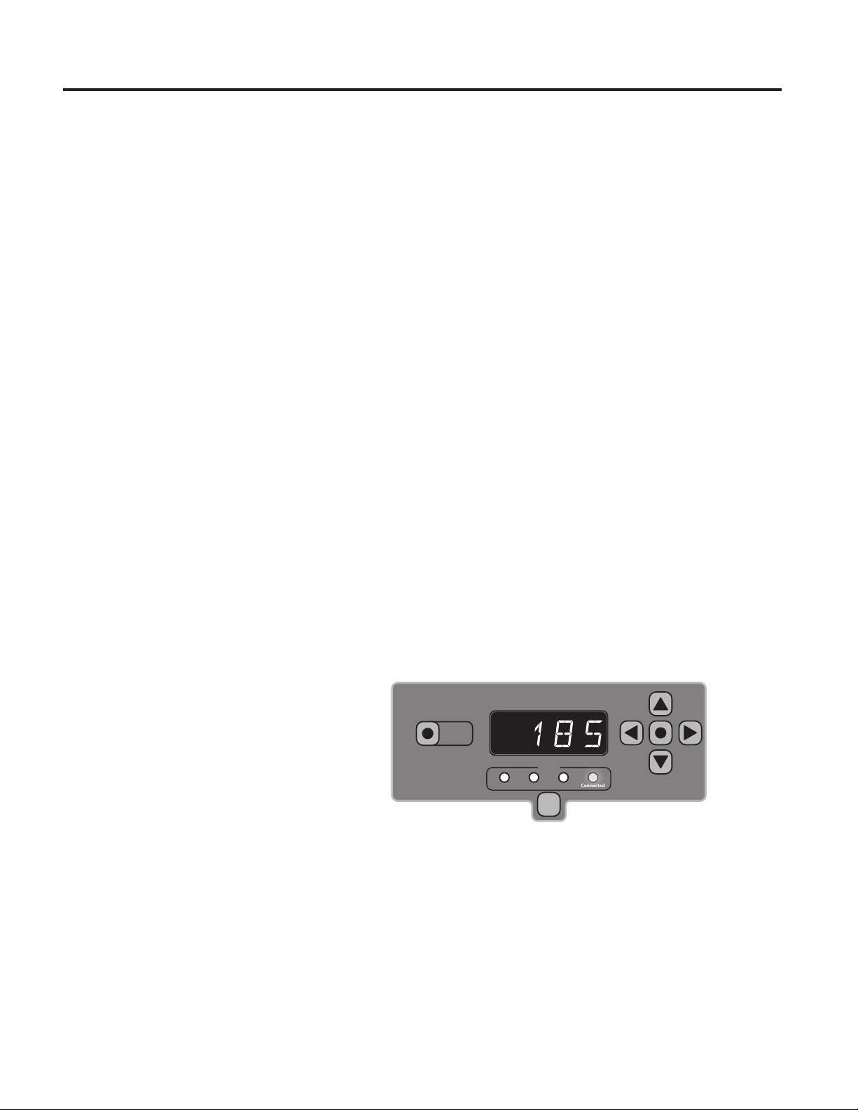
Adjusting Water Temperature Setpoint
e LED display alternates between the furnace water temperature (displays for
6 seconds) and the combustion temperature in the Reaction Chamber (displays
for 3 seconds).
To display the water temperature setpoint, press the Menu button.
e controller has been preset at the factory to 185˚F (85˚C). e water
temperature setpoint can be adjusted between 170˚F-195˚F (76˚C-91˚C).
NOTE: To reduce condensation in the rebox, it is recommended to set the temperature at
or above 185°F (85˚C).
NOTE: If the outdoor furnace overheats or boils over, lower the setpoint.
To change the water temperature setpoint, press and hold the Menu
button; then press the button to raise the water temperature setpoint, or the
button to lower the water temperature setpoint. After releasing the Menu
button, the LED display will indicate the actual temperature of the system
water.
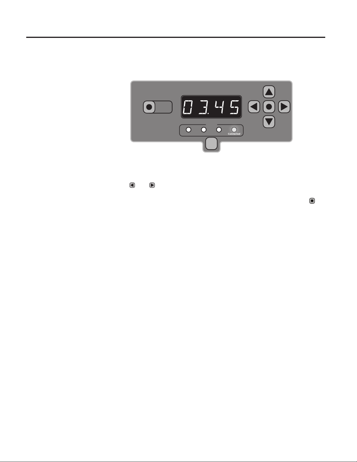
Reaction Chamber Temperature Reading
e LED display alternates between the furnace water temperature (displays for
6 seconds) and the combustion temperature in the Reaction Chamber (displays
for 3 seconds) during normal operation. To briey display the Reaction
Chamber temperature, press the button. Press the button four times
rapidly to display the water temperature without alternating (the right-most
decimal point will be illuminated). Pressing the button four more times
rapidly or shutting the controller power o and on again will return the LED
display to alternate between the furnace water temperature and the Reaction
Chamber temperature.
To Lock/Unlock Controller
e controller can be locked to prevent unauthorized access to the controller
settings. To lock the controller: Quickly press the button four times.
e LED display will indicate LOCKED for several seconds. To unlock the
controller: Quickly press the button four times. e LED display will
indicate UNLOCKED for several seconds.
NOTE: The controller can be locked while it is o. If the controller is locked while it is o, it
will have to be unlocked before it can be turned on.
Power Outage
In the event of a power outage, all controller settings will be saved. When
power is restored, the controller will continue operating as it was prior to the
power outage.