Central Forge 94428 User manual

®
Swivel Vise with Anvil
94428 94429
5” 6”
OPERATING INSTRUCTIONS
Due to continuing improvements, actual product may differ slightly from the product described herein.
®
3491 Mission Oaks Blvd., Camarillo, CA 93011
Visit our Web site at http://www.harborfreight.com
Copyright ©2006 by Harbor Freight Tools®. All rights reserved. No portion of this man-
ual or any artwork contained herein may be reproduced in any shape or form without
the express written consent of Harbor Freight Tools.
For technical questions or replacement parts, please call 1-800-444-3353

SKU 94428 & 94429 For technical questions please call 1-800-444-3353. Page 2
SPECIFICATIONS
94428 - 5” Vise 94429 - 6” Vise
Material Cast Iron Base
Finish Dark Blue with Chrome Adjusters
Overall Dimension 161/4” L x 63/4” W x 73/4” H 18” L x 73/4” W x 83/4” H
Dia. of Mounting Holes 1/2”
Jaw Material Heat-treated Medium Carbon Steel
Leadscrew Type 4 TPI x 1” Diameter
Handle Type Sliding “T”
Base Swivel 360° 120°
Weight 42 lb. 63 lb.
Capacity 61/4” x 3” Throat Depth 71/2” x 31/4” Throat Depth
SAVE THIS MANUAL
You will need the manual for the safety warnings and precautions, operating and main-
tenance procedures, parts list and diagram. Keep your invoice with this manual. Write
the invoice number on the inside of the front cover. Keep the manual and invoice in a
safe and dry place for future reference.
SAFETY WARNINGS AND PRECAUTIONS
KEEP PRODUCT USAGE AREA CLEAN. Cluttered areas invite injuries.
KEEP CHILDREN AWAY FROM PRODUCT USAGE AREA. Do not allow children
to handle this product.
DO NOT USE THIS PRODUCT IF UNDER THE INFLUENCE OF ALCOHOL OR
DRUGS. Read warning labels on prescriptions to determine if your judgement or re-
flexes are impaired while taking drugs. If there is any doubt, do not use this product.
USE EYE PROTECTION. Wear ANSI-approved safety impact goggles. Goggles are
available from Harbor Freight Tools.
DRESS SAFELY. Do not wear loose clothing or jewelry as they can become caught
in moving parts. Wear a protective hair covering to prevent long hair from becoming
caught in the moving parts.
DO NOT OVERREACH. Keep proper footing and balance at all times.
STAY ALERT. Watch what you are doing at all times. Use common sense. Do not
operate this product when you are tired or distracted from the job at hand.
CHECK FOR DAMAGED PARTS. Before using this product, carefully check that it
will operate properly and perform its intended function. Check for damaged parts
and any other conditions that may affect its operation. Replace or repair damaged or
worn parts immediately.
1.
2.
3.
4.
5.
6.
7.
8.

SKU 94428 & 94429 For technical questions please call 1-800-444-3353. Page 3
REPLACEMENT PARTS AND ACCESSORIES. When servicing, use only identical
replacement parts. Only use accessories intended for use with this product. Ap-
proved accessories are available from Harbor Freight Tools.
MAINTAIN PRODUCT WITH CARE. Keep this product clean and dry, and moving
parts lightly lubricated for better performance. Keep the Handle dry, clean and free
from oil, grease, and solvents.
USE THE RIGHT PRODUCT FOR THE RIGHT JOB. Do not attempt to force a small
tool or attachment to do the work of a larger industrial tool. There are certain applica-
tions for which this tool was designed. It will do the job better and more safely at the
rate for which it was intended. Do not modify this tool and do not use this tool for any
purpose other than which it was intended.
UNPACKING
When unpacking, check to make sure all parts shown on the Parts List (page 6) are in-
cluded. If any parts are missing or broken, please call Harbor Freight Tools at the number
shown on the cover of this manual as soon as possible.
9.
10.
11.
NOTE: All parts below refer to the parts listed on page 6 of this manual. Use 3/16”
diameter bolts of the appropriate length when mounting your Vise. Bolts, Lock Washers
and Nuts for mounting are NOT provided. You can mount the Vise or use it in a portable
manner, depending on what product you are working on or with.
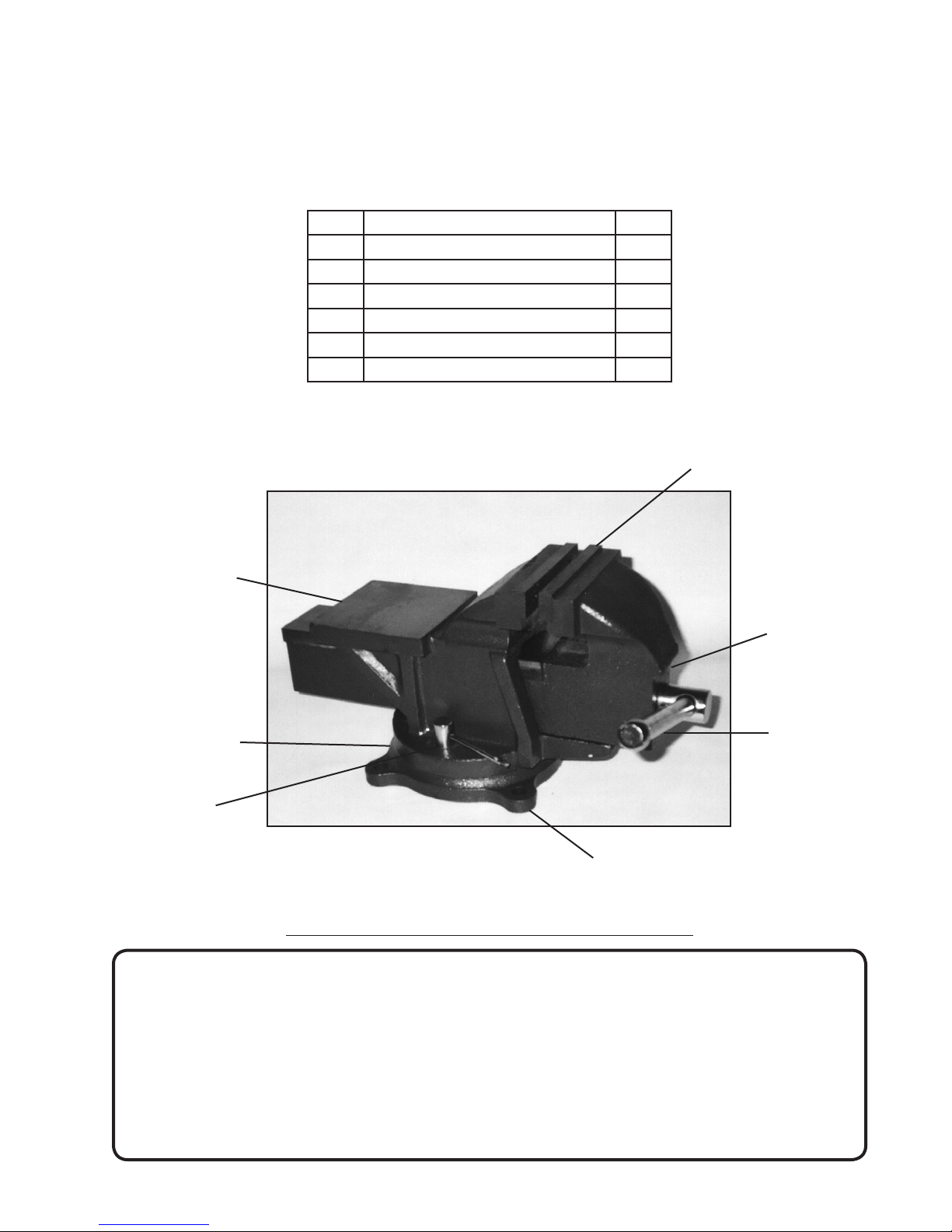
Setting Up The Vise:
Use the mounting holes on the Vise Base Plate (1) as a template. Set the Vise flat
on the workbench and, with a pencil, mark the points at which to fasten the Vise onto
the workbench. Set the Vise aside.
Drill holes of the appropriate size (where previously marked with a pencil) through
the top of the workbench. Caution: Before drilling holes, check for hidden electrical
wires or cords in drilling path.
Carefully set the Fixed Base (1) of the Vise with the Mounting Holes corresponding
to the holes previously drilled through the top of the workbench.
See Figure 1 next page.
Insert hardened steel bolts (not provided), of the appropriate diameter (to fit 1/2”
diameter mounting holes) and length, downward through the Fixed Base (1) and
through the workbench. The length of the mounting bolts will be determined by the
thickness of the workbench. Secure the mounting bolts in place with the appropriate
washers and nuts.
1.
2.
3.
4.

SKU 94428 & 94429 For technical questions please call 1-800-444-3353. Page 4
Fixed Base (1)
Figure 1
OPERATING INSTRUCTIONS
Turn the Handle (6) counterclockwise to open the Jaws (3) of the Vise. Place the
workpiece you are working on inside the Jaws. Tighten Jaws (3) against the work-
piece by turning the Handle (6) clockwise until your workpiece is held securely
against the Jaws (3). Caution: Damage could occur to your workpiece if you over-
tighten the Handle (6). See Figure 2.
To remove the object you are working on, turn the Handle (6) counterclockwise two
to three times, opening the Jaws (3). Remove your workpiece.
1.
2.
Mounting
Holes (Qty.3)
Figure 2
Handle (6)
Fixed
Base (1)
Jaw (3)
Jaw (3)
Anvil
Swivel
Base (5)
Locking
T-Handle (4)

SKU 94428 & 94429 For technical questions please call 1-800-444-3353. Page 5
Swivel the Mounted Vise
By swiveling the Vise around you can access your workpiece easier.
Turn the two Locking T-Handles (4) until they release the Swivel Base (5) of the Vise.
Turn the Vise to the desired position. (Example: Swivel 125°). See Figure 3.
Tighten the Locking T-Handles (4) once you have the Vise in the position best suited
for your work. See Figure 3.
1.
2.
3.
Maintenance
Keep the moving parts oiled, being sure to wipe off any excess oil off of the Handle
(6) and Jaws (3).
Keep the Jaws (3) clean so your workpiece will not be soiled.
Check and tighten the screws to be sure the vise has not loosened from it’s mount-
ing.
1.
2.
3.
Figure 3
Fixed
Base (1)
Locking
T-Handle (4)
Swivel Base (5)
Handle (6)
Anvil
Jaws (3)
Caution: When working with the Anvil, do not strike with a hardened tool. It could chip the
Anvil.

SKU 94428 & 94429 For technical questions please call 1-800-444-3353. Page 6
PARTS LIST
Note: When ordering parts, make sure to specify which model you are
ordering parts for.
Part Description Q’ty
1 Fixed Base 1
2 Lead Screw 1
3 Jaw 1
4 T-Locking Handle 2
5 Swivel Base 1
6 Handle 1
Note: Some parts are listed and shown for illustration purposes only and are not available as replacement parts.
PARTS DIAGRAM
1
4
5
6
Anvil
3
Mounting Hole
PLEASE READ THE FOLLOWING CAREFULLY
THE MANUFACTURER AND/OR DISTRIBUTOR HAS PROVIDED THE PARTS DIAGRAM IN THIS
MANUAL AS A REFERENCE TOOL ONLY. NEITHER THE MANUFACTURER NOR DISTRIBUTOR
MAKES ANY REPRESENTATION OR WARRANTY OF ANY KIND TO THE BUYER THAT HE OR SHE
IS QUALIFIED TO MAKE ANY REPAIRS TO THE PRODUCT OR THAT HE OR SHE IS QUALIFIED TO
REPLACE ANY PARTS OF THE PRODUCT. IN FACT, THE MANUFACTURER AND/OR DISTRIBUTOR
EXPRESSLY STATES THAT ALL REPAIRS AND PARTS REPLACEMENTS SHOULD BE UNDERTAKEN
BY CERTIFIED AND LICENSED TECHNICIANS AND NOT BY THE BUYER. THE BUYER ASSUMES
ALL RISK AND LIABILITY ARISING OUT OF HIS OR HER REPAIRS TO THE ORIGINAL PRODUCT OR
REPLACEMENT PARTS THERETO, OR ARISING OUT OF HIS OR HER INSTALLATION OF REPLACE-
MENT PARTS THERETO.

SKU 94428 & 94429 For technical questions please call 1-800-444-3353. Page 7
LIMITED 90 DAY
WARRANTY
Harbor Freight Tools Co. makes every effort to assure that its products meet high quality and durability standards,
and warrants to the original purchaser that this product is free from defects in materials and workmanship for
the period of 90 days from the date of purchase. This warranty does not apply to damage due directly or
indirectly, to misuse, abuse, negligence or accidents, repairs or alterations outside our facilities, or to lack of
maintenance. We shall in no event be liable for death, injuries to persons or property, or for incidental, contingent,
special or consequential damages arising from the use of our product. Some states do not allow the exclusion
or limitation of incidental or consequential damages, so the above limitation of exclusion may not apply to you.
THIS WARRANTY IS EXPRESSLY IN LIEU OF ALL OTHER WARRANTIES, EXPRESS OR IMPLIED,
INCLUDING THE WARRANTIES OF MERCHANTABILITY AND FITNESS.
To take advantage of this warranty, the product or part must be returned to us with transportation charges
prepaid. Proof of purchase date and an explanation of the complaint must accompany the merchandise. If our
inspection verifies the defect, we will either repair or replace the product at our election or we may elect to
refund the purchase price if we cannot readily and quickly provide you with a replacement. We will return
repaired products at our expense, but if we determine there is no defect, or that the defect resulted from
causes not within the scope of our warranty, then you must bear the cost of returning the product.
This warranty gives you specific legal rights and you may also have other rights which vary from state to state.
3491 Mission Oaks Blvd. • PO Box 6009 • Camarillo, CA 93011 • (800) 444-33533491 Mission Oaks Blvd. • PO Box 6009 • Camarillo, CA 93011 • (800) 444-3353
3491 Mission Oaks Blvd. • PO Box 6009 • Camarillo, CA 93011 • (800) 444-3353
This manual suits for next models
1
Table of contents
Other Central Forge Power Tools manuals

Central Forge
Central Forge CENTRAL FORGE 38413 User manual

Central Forge
Central Forge 40728 Parts list manual

Central Forge
Central Forge 93517 User manual

Central Forge
Central Forge 98656 User manual

Central Forge
Central Forge 94101 User manual

Central Forge
Central Forge 95844 User manual

Central Forge
Central Forge 94386 User manual

Central Forge
Central Forge 38388 User manual