manuals.online logo
Brands
  1. Home
  2. •
  3. Brands
  4. •
  5. Central Machinery
  6. •
  7. Mixer
  8. •
  9. Central Machinery 67536 Assembly instructions

Central Machinery 67536 Assembly instructions

Other manuals for 67536

2

Other Central Machinery Mixer manuals

Central Machinery 67536 Assembly instructions

Central Machinery

Central Machinery 67536 Assembly instructions

Central Machinery 67536 Assembly instructions

Central Machinery

Central Machinery 67536 Assembly instructions

Central Machinery 95906 Parts list manual

Central Machinery

Central Machinery 95906 Parts list manual

Popular Mixer manuals by other brands

Oster FPSTSM2710 instruction manual

Oster

Oster FPSTSM2710 instruction manual

Aviom A-16II user guide

Aviom

Aviom A-16II user guide

Varimixer V30K Spare part and operation manual

Varimixer

Varimixer V30K Spare part and operation manual

Kohler Stillness K-T954 installation guide

Kohler

Kohler Stillness K-T954 installation guide

Wolf Gourmet WGSM300 Use & care guide

Wolf Gourmet

Wolf Gourmet WGSM300 Use & care guide

Team International TEAM MS 17 operating instructions

Team International

Team International TEAM MS 17 operating instructions

MULTIQUIP Whiteman WM45E Operation and parts manual

MULTIQUIP

MULTIQUIP Whiteman WM45E Operation and parts manual

KitchenAid KSM7581BZ0 Instructions and recipes

KitchenAid

KitchenAid KSM7581BZ0 Instructions and recipes

Jay-Lor 5050 owner's manual

Jay-Lor

Jay-Lor 5050 owner's manual

privileg MJ-BL1051W user manual

privileg

privileg MJ-BL1051W user manual

Fakir CULINA CHEF user manual

Fakir

Fakir CULINA CHEF user manual

Termozeta Bellacucina Instruction booklet

Termozeta

Termozeta Bellacucina Instruction booklet

Thinky ARE-250 instruction manual

Thinky

Thinky ARE-250 instruction manual

Midas XL4 manual

Midas

Midas XL4 manual

bianco PURO 4 manual

bianco

bianco PURO 4 manual

better chef IM-815WC Use and care book

better chef

better chef IM-815WC Use and care book

ALLEN & HEATH GR1 user guide

ALLEN & HEATH

ALLEN & HEATH GR1 user guide

Buffalo CP921 instruction manual

Buffalo

Buffalo CP921 instruction manual

manuals.online logo
manuals.online logoBrands
  • About & Mission
  • Contact us
  • Privacy Policy
  • Terms and Conditions

Copyright 2025 Manuals.Online. All Rights Reserved.

!"#"$%&'(%)*+#"$*%,$-%.$$/-00)))1.,(+&(2(*"3.$14&5
65,"7%&'(%$*4.8"4,7%#'//&($%,$-%/(&9'4$#'//&($:.,(+&(2(*"3.$14&5
!"#"$%&'(%)*+#"$*%,$-%.$$/-00)))1.,(+&(2(*"3.$14&5
65,"7%&'(%$*4.8"4,7%#'//&($%,$-%/(&9'4$#'//&($:.,(+&(2(*"3.$14&5
NOTICE
FOR CEMENT AND
MORTAR ONLY.
Do not use with Epoxy
2-part resin mix.
Owner’s Manual & Safety Instructions
Save This Manual Keep this manual for the safety warnings and precautions, assembly,
operating, inspection, maintenance and cleaning procedures. Write the product’s serial number in the
back of the manual near the assembly diagram (or month and year of purchase if product has no number).
Keep this manual and the receipt in a safe and dry place for future reference. 20i
When unpacking, make sure that the product is intact
and undamaged. If any parts are missing or broken,
please call 1-888-866-5797 as soon as possible.
Copyright© 2013 by Harbor Freight Tools®. All rights reserved.
No portion of this manual or any artwork contained herein may be reproduced in
any shape or form without the express written consent of Harbor Freight Tools.
Diagrams within this manual may not be drawn proportionally. Due to continuing
improvements, actual product may differ slightly from the product described herein.
Tools required for assembly an d se rv ic e may n ot b e in cl uded.
Read this material before using this product.
Failure to do so can result in serious injury.
SAVE THIS MANUAL.
Page 2 ;&(%$*4.8"4,7%<'*#$"&8#=%/7*,#*%4,77%>?@@@?@AA?BCDC1 Item 67536
NOTICE
FOR CEMENT AND MORTAR ONLY.
Do not use with Epoxy 2-part resin mix.
EF;6GH IJ6KFGLIM NFLMG6MFMO6E6GPJ
NOTICE
FOR CEMENT AND MORTAR ONLY.
Do not use with Epoxy 2-part resin mix.
G,+7*%&2%O&8$*8$#
Safety ......................................................... 3
Specifications ............................................. 6
Setup .......................................................... 7
Operation ................................................... 10
Maintenance .............................................. 12
Parts List and Diagram .............................. 14
Warranty .................................................... 16
QFKMLMR%EHNSITE%FMU%U6;LMLGLIME
This is the safety alert symbol. It is used to alert you to potential
personal injury hazards. Obey all safety messages that
follow this symbol to avoid possible injury or death.
Indicates a hazardous situation which, if not avoided,
will result in death or serious injury.
Indicates a hazardous situation which, if not avoided,
could result in death or serious injury.
Indicates a hazardous situation which, if not avoided,
could result in minor or moderate injury.
Addresses practices not related to personal injury.
Page 3;&(%$*4.8"4,7%<'*#$"&8#=%/7*,#*%4,77%>?@@@?@AA?BCDC1Item 67536
NOTICE
FOR CEMENT AND MORTAR ONLY.
Do not use with Epoxy 2-part resin mix.
EF;6GHIJ6KFGLIMNFLMG6MFMO6 E6GPJ
NOTICE
FOR CEMENT AND MORTAR ONLY.
Do not use with Epoxy 2-part resin mix.
LNJIKGFMG%EF;6GH%LM;IKNFGLIM
% QFKMLMR%K*,9%,77%#,2*$V%),(8"83#%,89%"8#$('4$"&8#1%Failure to follow the warnings and instructions
may result in electric shock, fire and/or serious injury.
E,W*%,77%),(8"83#%,89%"8#$('4$"&8#%2&(%2'$'(*%(*2*(*84*1
F##*5+7V%J(*4,'$"&8#
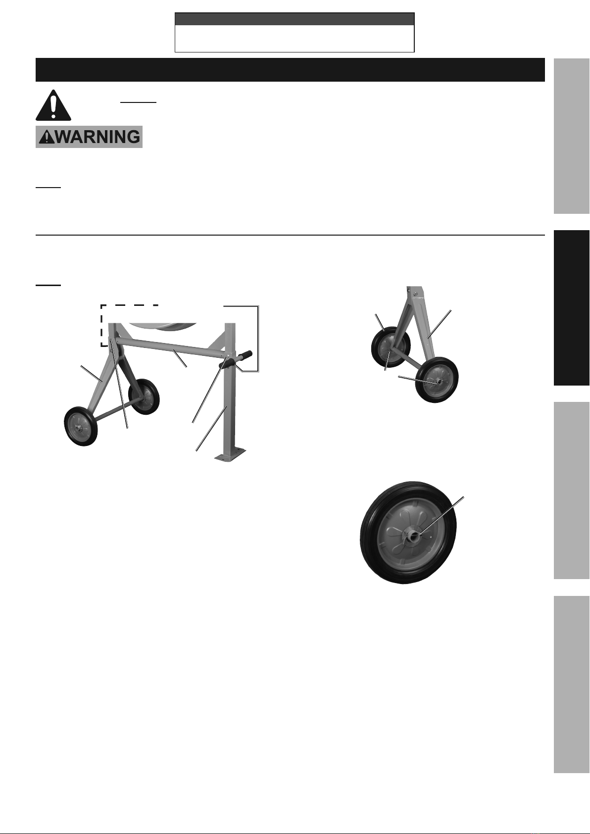
1. Assemble only according to these instructions.
Improper assembly can create hazards.
2. Wear ANSI-approved safety goggles and
heavy-duty work gloves during assembly.
3. Keep assembly area clean and well lit.
4. Keep bystanders out of the area during assembly.
5. Do not assemble when tired or when under the
influence of alcohol, drugs or medication.
6. Weight capacity and other product capabilities apply
to properly and completely assembled product only.
P#*%J(*4,'$"&8#
1. This product is not a toy. Do not allow
children to play with or near this item.
2. Use as intended only.
3. Inspect before every use; do not use
if parts are loose or damaged.
4. Do not exceed listed weight capacity.
S*%,),(*%&2%9V8,5"4%7&,9"83X
Sudden load movement may briefly create
excess load causing product failure.
5. DO NOT OVERLOAD MIXER. An
overload can damage equipment.
6. DO NOT MOVE MIXER DURING OPERATION.
The Mixer can tip over or motor could be damaged.
7. KEEP SAFE CLEARANCE AROUND MIXER.
Keep all persons (except operator) at least
six feet from Mixer during operation.
8. DON’T USE IN DANGEROUS ENVIRONMENT.
Don’t use power tools in damp or wet locations, or
expose them to rain. Keep work area well lighted.
9. KEEP CHILDREN AWAY. All visitors should
be kept safe distance from work area.
10. MAKE WORKSHOP KID PROOF with padlocks,
master switches, or by removing starter keys.
11. DON’T FORCE TOOL. It will do the job better
and safer at the rate for which it was designed.
12. USE RIGHT TOOL. Don’t force tool or attachment
to do a job for which it was not designed.
13. USE PROPER EXTENSION CORD. Make sure
your extension cord is in good condition. When
using an extension cord, be sure to use one
heavy enough to carry the current your product
will draw. An undersized cord will cause a drop
in line voltage resulting in loss of power and
overheating. %Table A shows the correct size to use
depending on cord length and nameplate ampere
rating. If in doubt, use the next heavier gauge. The
smaller the gauge number, the heavier the cord.
14. WEAR PROPER APPAREL. Do not wear loose
clothing, gloves, neckties, rings, bracelets, or
other jewelry which may get caught in moving
parts. Nonslip footwear is recommended. Wear
protective hair covering to contain long hair.
15. SECURE WORK. Use clamps or a vise to hold
work when practical. It’s safer than using your
hand and it frees both hands to operate tool.
16. DON’T OVERREACH. Keep proper
footing and balance at all times.
17. MAINTAIN TOOLS WITH CARE. Keep
tools sharp and clean for best and safest
performance. Follow instructions for
lubricating and changing accessories.
18. DISCONNECT TOOLS before servicing;
when changing accessories, such as
blades, bits, cutters, and the like.
19. REDUCE THE RISK OF UNINTENTIONAL
STARTING. Make sure switch is in
off position before plugging in.
20. NEVER STAND ON TOOL. Serious injury
could occur if the tool is tipped or if the
cutting tool is unintentionally contacted.
21. NEVER LEAVE TOOL RUNNING
UNATTENDED. TURN POWER OFF. Don’t
leave tool until it comes to a complete stop.
22. Maintain product labels and nameplates.
These carry important safety information.
If unreadable or missing, contact
Harbor Freight Tools for a replacement.
Page 4 ;&(%$*4.8"4,7%<'*#$"&8#=%/7*,#*%4,77%>?@@@?@AA?BCDC1 Item 67536
NOTICE
FOR CEMENT AND MORTAR ONLY.
Do not use with Epoxy 2-part resin mix.
EF;6GH IJ6KFGLIM NFLMG6MFMO6E6GPJ
NOTICE
FOR CEMENT AND MORTAR ONLY.
Do not use with Epoxy 2-part resin mix.
R(&'89"83
GI%JK6!6MG%6T6OGKLO%EYIOZ%FMU%U6FGY%;KIN%
LMOIKK6OG%RKIPMULMR%QLK6%OIMM6OGLIM-%
O.*4[%)"$.%,%<',7"2"*9%*7*4$("4",8%"2%V&'%,(*%"8%9&'+$%,#%$&%).*$.*(%$.*%&'$7*$%"#%/(&/*(7V%
3(&'89*91%%U&%8&$%5&9"2V%$.*%/&)*(%4&(9%/7'3%/(&W"9*9%)"$.%$.*%$&&71%%M*W*(%(*5&W*%$.*%
3(&'89"83%/(&83%2(&5%$.*%/7'31%%U&%8&$%'#*%$.*%$&&7%"2%$.*%/&)*(%4&(9%&(%/7'3%"#%9,5,3*91%%L2%9,5,3*9=%.,W*%
"$%(*/,"(*9%+V%,%#*(W"4*%2,4"7"$V%+*2&(*%'#*1%%L2%$.*%/7'3%)"77%8&$%2"$%$.*%&'$7*$=%.,W*%,%/(&/*(%&'$7*$%"8#$,77*9%+V%
,%<',7"2"*9%*7*4$("4",81
R(&'89*9%G&&7#-%G&&7#%)"$.%G.(**%J(&83%J7'3#
\?J(&83%J7'3%,89%I'$7*$
1. Tools marked with “Grounding Required” have
a three wire cord and three prong grounding
plug. The plug must be connected to a properly
grounded outlet. If the tool should electrically
malfunction or break down, grounding provides
a low resistance path to carry electricity away
from the user, reducing the risk of electric
shock. ]E**%\?J(&83%J7'3%,89%I'$7*$1^
2. The grounding prong in the plug is connected
through the green wire inside the cord to the
grounding system in the tool. The green wire
in the cord must be the only wire connected
to the tool’s grounding system and must
never be attached to an electrically “live”
terminal. ]E**%\?J(&83%J7'3%,89%I'$7*$1^
3. The tool must be plugged into an appropriate outlet,
properly installed and grounded in accordance
with all codes and ordinances. The plug and outlet
should look like those in the preceding illustration.
]E**%\?J(&83%J7'3%,89%I'$7*$1^
6_$*8#"&8%O&(9#
1. Grounded tools require a three wire extension cord.
Double Insulated tools can use either
a two or three wire extension cord.
2. As the distance from the supply outlet increases,
you must use a heavier gauge extension cord.
Using extension cords with inadequately sized wire
causes a serious drop in voltage, resulting in loss of
power and possible tool damage. ]E**%G,+7*%F1^
3. The smaller the gauge number of the wire, the
greater the capacity of the cord. For example,
a 14 gauge cord can carry a higher current
than a 16 gauge cord. ]E**%G,+7*%F1^
4. When using more than one extension cord
to make up the total length, make sure
each cord contains at least the minimum
wire size required. ]E**%G,+7*%F1^
5. If you are using one extension cord for more
than one tool, add the nameplate%amperes
and use the sum to determine the required
minimum cord size. ]E**%G,+7*%F1^
6. If you are using an extension cord outdoors, make
sure it is marked with the suffix “W-A” (“W” in
Canada) to indicate it is acceptable for outdoor use.
7. Make sure the extension cord is properly wired
and in good electrical condition. Always replace
a damaged extension cord or have it repaired
by a qualified electrician before using it.
8. Protect the extension cords from sharp objects,
excessive heat, and damp or wet areas.
Page 5;&(%$*4.8"4,7%<'*#$"&8#=%/7*,#*%4,77%>?@@@?@AA?BCDC1Item 67536
NOTICE
FOR CEMENT AND MORTAR ONLY.
Do not use with Epoxy 2-part resin mix.
EF;6GHIJ6KFGLIMNFLMG6MFMO6 E6GPJ
NOTICE
FOR CEMENT AND MORTAR ONLY.
Do not use with Epoxy 2-part resin mix.
GFST6%F-%%K6OINN6MU6U%NLMLNPN%QLK6%
RFPR6%;IK%6`G6MELIM%OIKUEa%]>bc0bdc%!ITG^
MFN6JTFG6
FNJ6K6E
],$%2'77%7&,9^
6`G6MELIM%OIKU%
T6MRGY
bBe Bce CBe >cce >Bce
0 – 2.0 18 18 18 18 16
2.1 – 3.4 18 18 18 16 14
3.5 – 5.0 18 18 16 14 12
5.1 – 7.0 18 16 14 12 12
7.1 – 12.0 18 14 12 10 -
12.1 – 16.0 14 12 10 - -
16.1 – 20.0 12 10 - - -
a%S,#*9%&8%7"5"$"83%$.*%7"8*%W&7$,3*%9(&/%$&%2"W*%W&7$#%,$%
>Bcf%&2%$.*%(,$*9%,5/*(*#1
O&88*4$"83%O&(9#
To reduce the risk of the cords pulling apart
during operation, do one of the following:
a. Make a knot as shown below
then connect the cords:
b.
6_$*8#"&8%
O&(9
F//7",84*%
O&(9
>
b
Or, use a plug-receptacle retaining
strap or connector designed to hold
extension cords to appliance cords.
N"_*(%E,2*$V%Q,(8"83#
1. ;IK%O6N6MG%FMU%NIKGFK%IMTH1%UI%MIG%
PE6%QLGY%6JI`H%b?JFKG%K6ELM%NL`1
QFKMLMRX Do not attempt to move the Cement
Mixer when it is full and/or in operation. It is
unsafe to move the mixer while in this condition,
and serious injury to personnel could occur.
2. When servicing use only identical replacement parts.
3. Only use safety equipment that has been approved
by an appropriate standards agency. Unapproved
safety equipment may not provide adequate
protection. Eye protection must be ANSI-approved
and breathing protection must be NIOSH-approved
for the specific hazards in the work area.
4. Industrial applications must follow OSHA guidelines.
5. Maintain labels and nameplates on
the tool. These carry important safety
information. If unreadable or missing, contact
Harbor Freight Tools for a replacement.
6. Avoid unintentional starting. Prepare to
begin work before turning on the tool.
7. People with pacemakers should consult their
physician(s) before use. Electromagnetic fields in
close proximity to heart pacemaker could cause
pacemaker interference or pacemaker failure.
8. The warnings, precautions, and instructions
discussed in this instruction manual cannot
cover all possible conditions and situations
that may occur. It must be understood by the
operator that common sense and caution are
factors which cannot be built into this product,
but must be supplied by the operator.
!"+(,$"&8%E,2*$V
This tool vibrates during use. Repeated or
long-term exposure to vibration may cause
temporary or permanent physical injury,
particularly to the hands, arms and shoulders.
To reduce the risk of vibration-related injury:
1. Anyone using vibrating tools regularly or for an
extended period should first be examined by a
doctor and then have regular medical check-
ups to ensure medical problems are not being
caused or worsened from use. Pregnant women
or people who have impaired blood circulation
to the hand, past hand injuries, nervous system
disorders, diabetes, or Raynaud’s Disease should
not use this tool. If you feel any medical or
physical symptoms related to vibration (such as
tingling, numbness, and white or blue fingers),
seek medical advice as soon as possible.
2. Do not smoke during use. Nicotine reduces
the blood supply to the hands and fingers,
increasing the risk of vibration-related injury.
Page 6 ;&(%$*4.8"4,7%<'*#$"&8#=%/7*,#*%4,77%>?@@@?@AA?BCDC1 Item 67536
NOTICE
FOR CEMENT AND MORTAR ONLY.
Do not use with Epoxy 2-part resin mix.
EF;6GH IJ6KFGLIM NFLMG6MFMO6E6GPJ
NOTICE
FOR CEMENT AND MORTAR ONLY.
Do not use with Epoxy 2-part resin mix.
3. Wear suitable gloves to reduce the
vibration effects on the user.
4. Use tools with the lowest vibration when there
is a choice between different processes.
5. Include vibration-free periods each day of work.
6. To reduce vibration, maintain the tool as
explained in this manual. If any abnormal
vibration occurs, stop use immediately.
E/*4"2"4,$"&8#
Electrical Input 120 VAC / 60 Hz / 3.5 A
Motor No Load Speed 1820 RPM
Drum Speed 36 RPM
Drum Capacity 3-1/2 Cubic Feet
Drum Opening 15"
Page 7;&(%$*4.8"4,7%<'*#$"&8#=%/7*,#*%4,77%>?@@@?@AA?BCDC1Item 67536
NOTICE
FOR CEMENT AND MORTAR ONLY.
Do not use with Epoxy 2-part resin mix.
EF;6GHIJ6KFGLIMNFLMG6MFMO6 E6GPJ
E*$'/%?%S*2&(*%P#*
K*,9%$.*%6MGLK6%LNJIKGFMG%EF;6GH%LM;IKNFGLIM%#*4$"&8%,$%$.*%+*3"88"83%&2%$."#%9&4'5*8$%
"847'9"83%,77%$*_$%'89*(%#'+.*,9"83#%$.*(*"8%+*2&(*%#*$%'/%&(%'#*%&2%$."#%/(&9'4$1
GI%JK6!6MG%E6KLIPE%LMgPKH%;KIN%FOOLU6MGFT%IJ6KFGLIM-%
G'(8%$.*%J&)*(%E)"$4.%&2%$.*%$&&7%&22%+*2&(*%/*(2&(5"83%,8V%/(&4*9'(*%"8%$."#%#*4$"&81
M&$*- For additional information regarding the parts listed in the following pages,
refer to the Assembly Diagram near the end of this manual.
F##*5+7V0N&'8$"83
1. Place the Stand (78) into the Wheel Bracket (4)
so that bolt holes line up. See Figure A.
M&$*- Set Stand on its side for easier assembly.
Y*_%S&7$#%]Cc^=%Y*_%S&7$#%]Cc^=%
;7,$%Q,#.*(%]BB^=%;7,$%Q,#.*(%]BB^=%
Y*_%;7,83*%M'$%]B^Y*_%;7,83*%M'$%]B^
Q.**7%Q.**7%
S(,4[*$%]d^S(,4[*$%]d^
T*3%]CD^T*3%]CD^
E$,89%]C@^E$,89%]C@^
Y*_%S&7$#%]AD^=%Y*_%S&7$#%]AD^=%
;7,$%Q,#.*(%]BB^=%;7,$%Q,#.*(%]BB^=%
Y*_%;7,83*%M'$%]B^Y*_%;7,83*%M'$%]B^
;"3'(*%F
2. Fasten together using Hex Bolts (69, 70), Flat
Washers (55) and Hex Flange Nuts (5). Tighten
with a wrench (not included) until secure.
3. Insert Leg (79) into Stand so that bolt holes line up.
4. Fasten together using Hex Bolts (69, 70),
Flat Washers (55) and Hex Flange Nuts (5).
Tighten with a wrench until secure.
5. Place Stand upright.
6. To attach Wheels (3) to Wheel Bracket, slide a
Flat Washer (2), Wheel and second Flat Washer
onto each end of Bracket axle. See Figure B.
Q.**7%Q.**7%
S(,4[*$%]d^%S(,4[*$%]d^%
Q.**7%]\^Q.**7%]\^
;7,$%;7,$%
Q,#.*(%]b^Q,#.*(%]b^
;"3'(*%S
7. Insert a Cotter Pin (1) through holes in each end
of the Bracket axle and bend the Cotter Pins over
to secure the Wheels in place. See Figure C.
O&$$*(%O&$$*(%
J"8%]>^J"8%]>^
;"3'(*%O
Page 8 ;&(%$*4.8"4,7%<'*#$"&8#=%/7*,#*%4,77%>?@@@?@AA?BCDC1 Item 67536
NOTICE
FOR CEMENT AND MORTAR ONLY.
Do not use with Epoxy 2-part resin mix.
EF;6GH IJ6KFGLIM NFLMG6MFMO6E6GPJ
8. With assistance, set the Lower Drum (48)
with attached Arm (77) and Support
Bracket Seats (35) into Stand assembly
and align the bolt holes. See Figure D.
T&)*(%U('5%]d@^T&)*(%U('5%]d@^
E'//&($%S(,4[*$%E'//&($%S(,4[*$%
E*,$%]\B^E*,$%]\B^
F(5%]CC^F(5%]CC^
;"3'(*%U
9. Fasten together using Hex Bolts (71), Flat
Washers (55), and Hex Flange Nuts (5).
Tighten with wrench until secure.
10. Mount Handle Control Plate (41) to Support Bracket
Seat (35) using Hex Bolts (28), Spring Washers
(29) and Flat Washers (30). See Figure E.
Y,897*%O&8$(&7%J7,$*%]d>^Y,897*%O&8$(&7%J7,$*%]d>^
Y*_%S&7$% ]b@^=%%Y*_%S&7$% ]b@^=%%
Q,#.*(#%Q,#.*(#%
]bD%h%\c^]bD%h%\c^
F(5%]CC^F(5%]CC^
;7,$%Q,#.*(#%]dB^;7,$%Q,#.*(#%]dB^
8'$%]dd^8'$%]dd^
Y*_%S&7$%]db^Y*_%S&7$%]db^
O&"7%E/("83%]d\^O&"7%E/("83%]d\^
O&8$(&7%Y,897*%]dA^O&8$(&7%Y,897*%]dA^
;"3'(*%6
11. Tighten to a point where the Arm (77) can still move.
12. Insert the Coil Spring (43) into
the Control Handle (46).
13. Attach Control Handle to Arm shaft with a Hex
Bolt (42), two Flat Washers (45), and a nut (44).
14. Use gasket sealer (not included) to stick the Rubber
Gasket (60) to the Upper Drum (59), making sure
the holes in both align. The Gasket must be flat
on the Upper Drum to ensure a proper seal.
15. Place the Upper Drum onto the Lower Drum (48),
making sure the mounting holes align in both.
16. Insert a Screw (57) into each of six
mounting holes. Fasten Drums together
using Flat Washers (58) and Nuts (32).
17. Position each Mixer Blade (62) inside the assembled
Drum with the pointed end facing downward.
The V-shaped bend in the Blades should point in
the direction of the Drum rotation (clockwise).
18. Fasten tops of Mixer Blades to Upper Drum using
Hex Bolts (54), Washers (55), Seal Gaskets
(56), and Hex Flange Nuts (5). Fasten pointed
ends of Mixer Blades to Lower Drum using Hex
Bolts (61), Washers (55), Seal Gaskets (56),
Rubber Gaskets (63) and Hex Flange Nuts (5).
19. Mount the Motor Hood (31) to the Support
Bracket Seat (35) using Hex Bolts (28), Spring
Washers (29) and Flat Washers (30).
20. Use Hex Bolts (73), Flat Washers (55), Spring
Washers (29) and Clamp (72) to attach the
Motor Bracket (6) to the Motor Hood. Tighten
connections until secure. See Figure F.
Y*_%S&7$%Y*_%S&7$%
]C\^]C\^
;7,$%Q,#.*(%]BB^;7,$%Q,#.*(%]BB^
E/("83%Q,#.*(%]bD^E/("83%Q,#.*(%]bD^
O7,5/%]Cb^O7,5/%]Cb^
N&$&(%Y&&9%]\>^N&$&(%Y&&9%]\>^
N&$&(%O&W*(%]D^N&$&(%O&W*(%]D^
;"3'(*%;
Page 9;&(%$*4.8"4,7%<'*#$"&8#=%/7*,#*%4,77%>?@@@?@AA?BCDC1Item 67536
NOTICE
FOR CEMENT AND MORTAR ONLY.
Do not use with Epoxy 2-part resin mix.
EF;6GHIJ6KFGLIMNFLMG6MFMO6 E6GPJ
21. Clean the Pinion Shaft (36) of all protective
material and other debris. Clean debris
out of the Motor Pulley (66) hub.
22. Spread a few drops of lubricating oil on the Pinion
Shaft and squarely push the Drum Pulley (26)
onto the Shaft so that the groove in the Pulley
engages the Flat Key (25). The Pulley should
be flush with the step on the Pinion Shaft.
M&$*- Do not hammer the Drum Pulley onto the
Pinion Shaft. Doing so can damage the unit and
possibly lead to a loose fitting V-Belt (68).
23. Place the Motor (65) onto the Motor Bracket.
24. Use Hex Bolts (28), Flat Washers (55) and Hex
Flange Nuts (5) to secure the Motor to the Motor
Bracket. Hand-tighten all four nuts since the
motor will be adjusted forward or backward later.
25. Once the Drum Pulley is pushed in all the
way, use a hex key (not included) to tighten
the Screw on the side of the Pulley’s hub.
26. Attach the V-Belt by placing it around the Motor
Pulley (66) and then over the Drum Pulley.
Using a flat-edge screwdriver (not included),
push the Motor inward until the Motor Pulley
is directly under the Drum Pulley. Tighten the
Bolts securing the Motor to the Motor Bracket.
27. Slightly loosen the Hex Bolts (73) holding the Motor
Bracket in place. Push the Motor downward until
the V-Belt tension is tight. When proper V-Belt
tension is achieved, tighten the Hex Bolts (see
Belt Inspection and Tensioning on page 12).
28. Check if Motor and V-Belt turn correctly. Hand
turn the Drum Pulley and verify that Motor
Pulley and Drum Pulley do not rub against any
other part. Adjust Motor location as needed.
29. Mount the Motor Cover (9) to the Motor Hood (31)
using three Hex Bolts (16) and Nuts (32).
OFPGLIMX Make sure that the power cord from
the Motor to the Switch (13) does not come
in contact with any moving parts.
30. Check all connections to verify that all screws,
nuts, and bolts are securely tightened.
Page 10 ;&(%$*4.8"4,7%<'*#$"&8#=%/7*,#*%4,77%>?@@@?@AA?BCDC1 Item 67536
NOTICE
FOR CEMENT AND MORTAR ONLY.
Do not use with Epoxy 2-part resin mix.
EF;6GH IJ6KFGLIM NFLMG6MFMO6E6GPJ
I/*(,$"83%L8#$('4$"&8#
%K*,9%$.*%6MGLK6%LNJIKGFMG%EF;6GH%LM;IKNFGLIM%#*4$"&8%,$%$.*%+*3"88"83%&2%$."#%
5,8',7%"847'9"83%,77%$*_$%'89*(%#'+.*,9"83#%$.*(*"8%+*2&(*%#*$%'/%&(%'#*%&2%$."#%/(&9'4$1
;'84$"&8#
N"_*(%S7,9*
P//*(%U('5
N&$&(%F##*5+7V O&8$(&7%
Y,897*
E$,89
Q.**7%S(,4[*$
Q.**7
T&)*(%U('5
F(5
T*3
Y,897*%
O&8$(&7%
J7,$*