CE+T Power FLEXA 200 400/400 User manual

www.cet-power.com
Belgium, China, India, Luxembourg, Malaysia, Russia, United Kingdom, United States, Australia & Germany
FLEXA 200 - 400/400
INCLUDING SMART BYPASS (SBP)
User Manual V1.0
Copyright © 2013. Construction electroniques & telecommunications S.A.
All rights reserved. The contents in document are subject to change without notice.
The products presented are protected by several international patents and trademarks.
Address: CE+T S.a, Rue du Charbonnage 12, B 4020 Wandre, Belgium
www.cet-power.com - info@cet-power.com
• SELECTIVITY
Adapted response to short circuit and overload
• VERSATILE CHARGING
Short or long backup recovery time at no extra cost
• BATTERY SUSTAINABILITY
Qualitative charging for longer battery life expectancy
• HARSHEST AC INPUT CONDITIONS
Without compromising the quality of the AC output
RE-INVENTING THE MODULAR UPS
THE NEW GENERATION OF POWER CONVERTERS

2 – Flexa 200 - 400/400 – User Manual – v1.0
Table of Contents
1. CE+T Power at a glance.......................................................................................................................5
2. Abbreviations.......................................................................................................................................6
3. Introduction .........................................................................................................................................7
3.1 Scope of the manual .................................................................................................................7
3.2 User Interface presentation........................................................................................................7
3.2.1 Flexa 200 UPS module User Interface ..........................................................................7
3.2.2 T4S supervisor ...........................................................................................................11
3.2.3 CATENA GUI Interface .................................................................................................12
4. Hardware setup ................................................................................................................................14
4.1 Schematic Diagram - Common Input Source for Flexa with SBP + MBP .................................15
4.2 Schematic Diagram - Dual Input Source for Flexa with SBP + MBP .........................................16
5. T4S/CATENA start-up ........................................................................................................................18
5.1 Applying start-up power ..........................................................................................................18
6. Standard Features..............................................................................................................................19
6.1 AC Input Sub-menu .................................................................................................................20
6.2 DC Battery Sub-menu .............................................................................................................20
6.3 Flexa Modules Sub-menu.......................................................................................................21
6.3.1 Flexa Modules Sub-menu...........................................................................................21
6.4 AC Output Load Sub-menu......................................................................................................23
6.5 SBP Modules Sub-menu..........................................................................................................23
6.5.1 SBP Modules Sub-menu.............................................................................................24
7. Toolbar...............................................................................................................................................25
7.1 Events and Log........................................................................................................................25
7.2 Input, output mapping ............................................................................................................26
7.3 Files ........................................................................................................................................27
7.4 Parameters..............................................................................................................................28
7.4.1 Monitoring..................................................................................................................28
7.4.2 Communication ..........................................................................................................30
7.4.3 Digital Input and output relay mapping .......................................................................31
7.4.4 Power parameter setting ............................................................................................33
7.4.5 Battery 1 and Battery 2 ..............................................................................................37
7.4.6 Info ............................................................................................................................39
8. Flexa / SBP module and Fan replacement ..........................................................................................40
8.1 Flexa / SBP module replacement.............................................................................................40
8.2 Fan Replacement ....................................................................................................................41
9. Factory Ranges and Defaults..............................................................................................................42
9.1 Definition.................................................................................................................................43

3 – Flexa 200 - 400/400 – User Manual – v1.0
10. SNMP V1 & SNMP V3 Configuration....................................................................................................44
10.1 SNMPv1 configuration.............................................................................................................44
10.2 SNMPv1 MIB (RFC1628)..........................................................................................................44
10.3 SNMPv3 configuration.............................................................................................................44
11. ModBus RTU ......................................................................................................................................46
11.1 Physical Connection ................................................................................................................46
11.2 Configuration...........................................................................................................................47
11.3 Tables .....................................................................................................................................47
ANNEXE 1. Battery Management with Flexa Technology and T4S .............................................................48
1.1. Introduction ............................................................................................................................48
1.2. CE+T Battery charging and discharging MODE........................................................................48
ANNEXE 2. Flexa Manual Bypass (MBP) ..................................................................................................52
2.1. Introduction.............................................................................................................................52
2.2. Principle of operation .............................................................................................................52
2.3. Presentation ...........................................................................................................................53
2.4. MBP Wiring ............................................................................................................................54
ANNEXE 3. Flexa Smart By-Pass (SBP) ....................................................................................................55
3.1. Introduction.............................................................................................................................55
3.2. Principle of Operation .............................................................................................................55
3.3. SBP LEDs Indication ................................................................................................................57
3.4. SBP Breaker Selection.............................................................................................................58
ANNEXE 4. T4S Alarms ............................................................................................................................58
4.1. Supervisor alarms: T4S ...........................................................................................................58
ANNEXE 5. FAQ........................................................................................................................................68
Release Note:
Version Release date
(DD/MM/YYYY)
Modified
page number Modifications
1.0 11/05/2020 - First release of the Manual.
4 – Flexa 200 - 400/400 – User Manual – v1.0

1. CE+T Power at a glance
CE+T Power designs, manufactures and markets a range of products for industrial operators with mission critical
applications, who are not satisfied with existing AC backup systems performance and related maintenance costs.
Our product is an innovative AC backup solution that unlike most used UPS’s
•Maximizes the operator’s applications uptime;
•Operates with lowest OPEX;
•Provides best protection to power disturbances;
•Optimizes footprint.
Our systems are:
•Modular
•Truly redundant
•Highly efficient
•Maintenance free
•Battery friendly
CE+T puts 60+ years expertise in power conversion together with worldwide presence to provide customized solutions
and extended services 24/7 – 365 days a year.
5 – Flexa 200 - 400/400 – User Manual – v1.0
CE+T Power at a glance
2. Abbreviations
TSI Twin Sine Innovation
EPC Enhanced Power Conversion
REG Regular
DSP Digital Signal Processor
AC Alternating current
DC Direct current
PE Protective Earth (also called Main Protective Conductor)
N Neutral
PCB Printed Circuit Board
TRS True Redundant Structure
PWR Power
ESD Electro Static Discharge
MET Main Earth Terminal
MBP Manual By-pass
MCB Miniature Circuit Breaker
MCCB Molded Case Circuit Breaker
CB Circuit Breaker
TCP/IP Transmission Control Protocol/Internet Protocol
USB Universal Serial Bus
LAN Local Access Network
ETH Ethernet
SNMP Simple Network Management Protocol
HTTP HyperText Transfer Protocol
HTTPS Secure HyperText Transfer Protocol
NTP Network Time Protocol
MIB Management Information Base
DHCP Dynamic Host Configuration Protocol
6 – Flexa 200 - 400/400 – User Manual – v1.0
Abbreviations

3. Introduction
3.1 Scope of the manual
This document describes the T4S and Catena touch screen operations, web interfaces, on-site setup, and operation
of the Flexa Modular Power system. Please refer to the Flexa Installation manual for hardware installation and wiring
information.
3.2 User Interface presentation
3.2.1 Flexa 200 UPS module User Interface
Output power bar graph 0-100% (25% increment)
Phase 1, phase 2, phase 3
Module ON/OFF switch
AC Input/ AC output module status
DC input/ Communication module status
7 – Flexa 200 - 400/400 – User Manual – v1.0
Introduction

3.2.1.1 Output Power LED interface :
Each segment represent 25% load.
25 %
50 %
75 %
100 %
Load
Load can differ between the 3 phases in one module
Load can differ in one phase in several modules
Overload (blinking)
100% - 110% segment 0-25 blinking
110,1% - 135% segment 0-50 blinking
8 – Flexa 200 - 400/400 – User Manual – v1.0
Introduction

3.2.1.2 Module status LEDs interface
AC input LEDs interface
Starting up (all LEDs) OFF
AC Input OK (within limits) GREEN
AC Input not OK (out of limits) ORANGE
(Auto restart) Flash ORANGE
(Manual restart) Flash RED
(Non recoverable) RED
AC failure OFF + external alarm
AC output LEDs interface
Starting up ( ) GREEN Blink
AC Output OK (within limits) GREEN
AC Output not OK (out of limits) ORANGE
(auto restart) ORANGE Blink
(manual restart) RED Blink
(non recover) RED
Remote OFF (man restart) OR/GR/OR/GR
sequence every x seconds
9 – Flexa 200 - 400/400 – User Manual – v1.0
Introduction

Starting up ( ) OFF
DC OK (within limits) GREEN
DC not OK (out of limits) YELLOW
(auto restart) YELLOW Blink
(man restart) RED Blink
(non recover) RED
No battery
connected ( ) OFF
Communication LEDs interface
COM OK ( ) GREEN
COM ERROR (Bus A or B) GREEN Blink still one bus present
COM ERROR (Bus A & B) RED Blink
Module and system will continue working with one BUS failing with two bus failing
the module/system will isolate and shut down.
10 – Flexa 200 - 400/400 – User Manual – v1.0
Introduction

3.2.2 T4S supervisor
5
4
123
T4S supervisor monitors the Flexa 200 - 400/400 module as well as system environment. It is connected to:
•1 Connection from the Hub Board.
•2 To monitor the external device.
•3 Connection from Catena network port - see section 3.2.3.2, page 12.
•4 Connection from Auxiliary power supply kit (2 x 12 Vdc).
T4S has:
•8 “digital input “ referred to has D1 to D8.
•8 output relays Major Alarm, Minor Alarm, R3 to R8.
•3 temperature probes T1 to T3. T1 should used for battery 1 and T2 for battery 2, T3 is reserved for future.
•Modbus is available on RS485 port [5]. See section 11, page 46 for more information.
Please note the T4S and CATENA are not master and therefore can be removed during operation without affecting the
operation of the UPS AC output.
11 – Flexa 200 - 400/400 – User Manual – v1.0
Introduction

3.2.3 CATENA GUI Interface
CATENA GUI interface allows the user to easily access the system monitoring via a powerful web based graphic
display.
In addition to the touch-screen display the user can also access to the same GUI using an Ethernet port present on the
T4S or CATENA.
3.2.3.1 Software Overview
The software embedded in T4S and CATENA allows complete system supervision through “touchscreen display” or via
web browser, and provides functionalities such as:
•System setting and configuration (password protected).
•System status and information display.
•System alarms and events log file.
•System self-maintenance (battery test, battery boost charge,….).
3.2.3.2 CATENA comes in two versions:
•Rack mounted where the unit takes 3U inside the cabinet flush mounted.
•Door or Panel mounted where the unit is fixed to the door or panel.
Catena - Rack Mounting Version
Remark: Reset will only reset the Catena, not the T4S and will have no effect on the system.
Power supply and connectivity are provided on the back of the unit:
12 – Flexa 200 - 400/400 – User Manual – v1.0
Introduction

Catena - Door Mounting Version
To access the user interface, user has to connect through Ethernet port in Catena.
Installing the Door mount catena in the Flexa cabinet door
Step 1. In the Cabinet Door, make 8 x M3 holes as per the catena support sheet dimensions.
Step 2. Assemble the Door mount catena with the Catena support sheet using 4 x M3 Studs.
Step 3. Place the assembled catena into the cabinet door and fix it using 8 x M3 Studs.
13 – Flexa 200 - 400/400 – User Manual – v1.0
Introduction

14 – Flexa 200 - 400/400 – User Manual – v1.0
Hardware setup
4. Hardware setup
T4S is a DIN rail mountable controller which is connected to the Flexa 200 - 400/400 module / system as indicated in
the schematic in next page.
Remark: Catena acts as a switch on the network. Both T4S & Catena need IP address as they are both connected to
the network.
See section 7.4.2, page 30 for tips on network configuration.

15 – Flexa 200 - 400/400 – User Manual – v1.0
Hardware setup
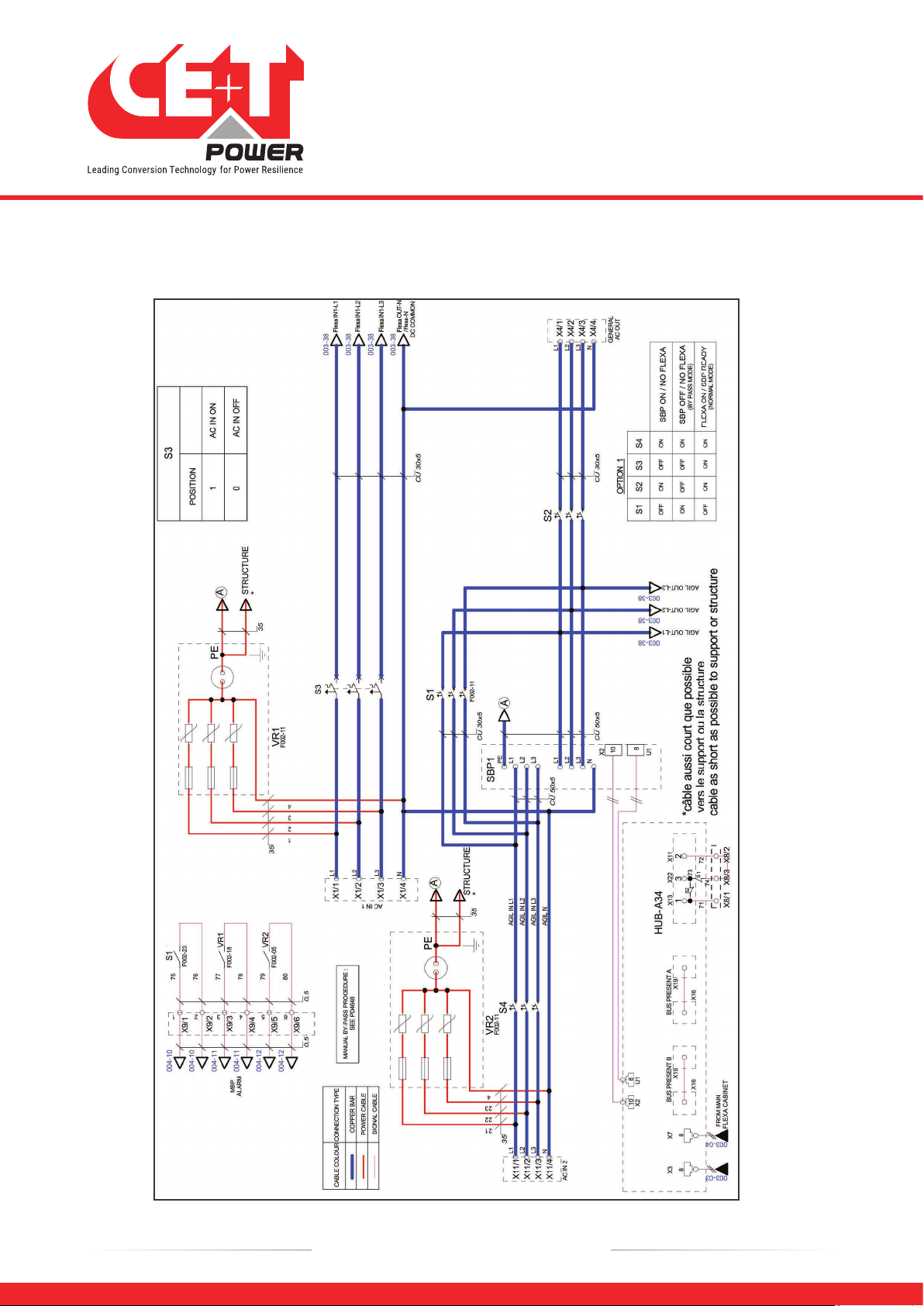
4.1 Schematic Diagram - Common Input Source for Flexa with SBP + MBP
16 – Flexa 200 - 400/400 – User Manual – v1.0
Hardware setup
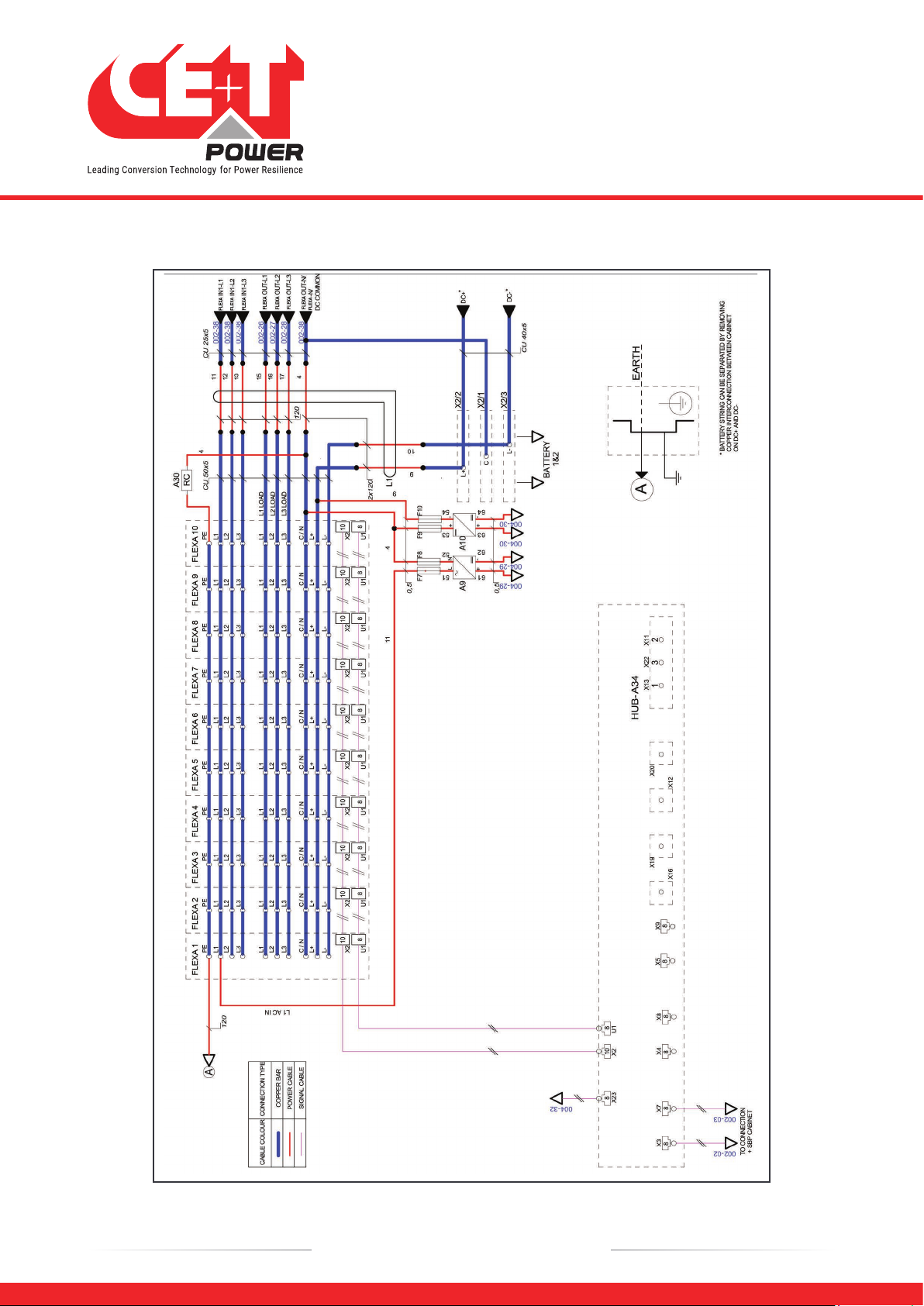
4.2 Schematic Diagram - Dual Input Source for Flexa with SBP + MBP
•Page 1
17 – Flexa 200 - 400/400 – User Manual – v1.0
Hardware setup
•Page 2
18 – Flexa 200 - 400/400 – User Manual – v1.0
T4S/CATENA start-up
5. T4S/CATENA start-up
If you have installed the T4S and CATENA by yourself, make sure to respect the connections as indicated in the
schematic.
If you have ordered the complete solution with cabinet and module from CE+T Power, both controllers are installed,
wired, tested and preconfigured according to the system.
5.1 Applying start-up power
NOTE: The controller will perform a short self-test as it boots up. Alarm alerts are normal.
•Initiate the start-up routine by applying power to the T4S (close protection breaker powering the controller).
•Use the touchscreen or a laptop to connect to the system.
NB: if you are connecting with your laptop, default IP address of user interface is http://192.168.0.2
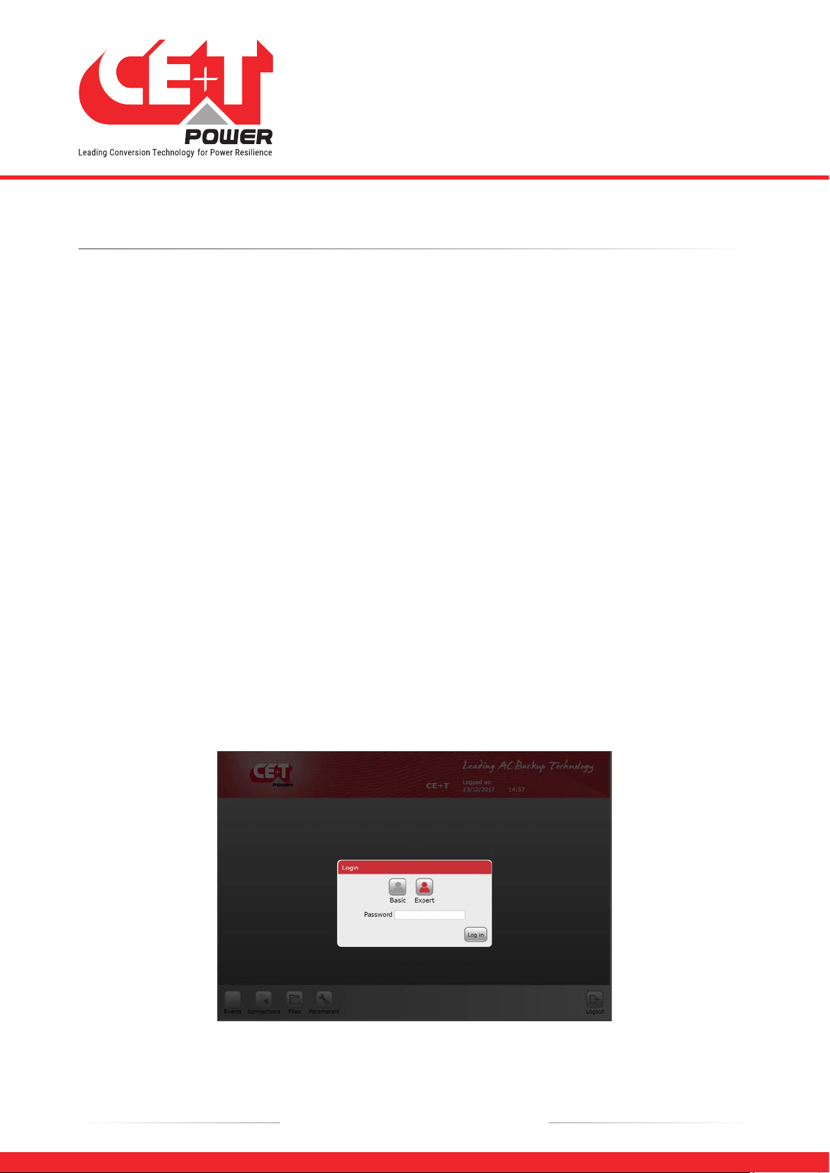
There are two access levels:
•Basic: after version 3.1, basic access does not require password. Before that, default password is
pass123
.
•Expert: default password is
pass456
but it’s strongly advised to users to change that password.
In case of lost password, please refer to FAQ at page 68
•Check and adjust alarms and control levels in the controller sub-menus.
•Check and adjust battery settings in the battery sub-menus; e.g. float, equalize voltage, etc.
•If on touchscreen, check the communications settings for remote access as needed.
NOTE: System modification and setting may result in alarm event. Make sure you are applying modification carefully.
19 – Flexa 200 - 400/400 – User Manual – v1.0
Standard Features
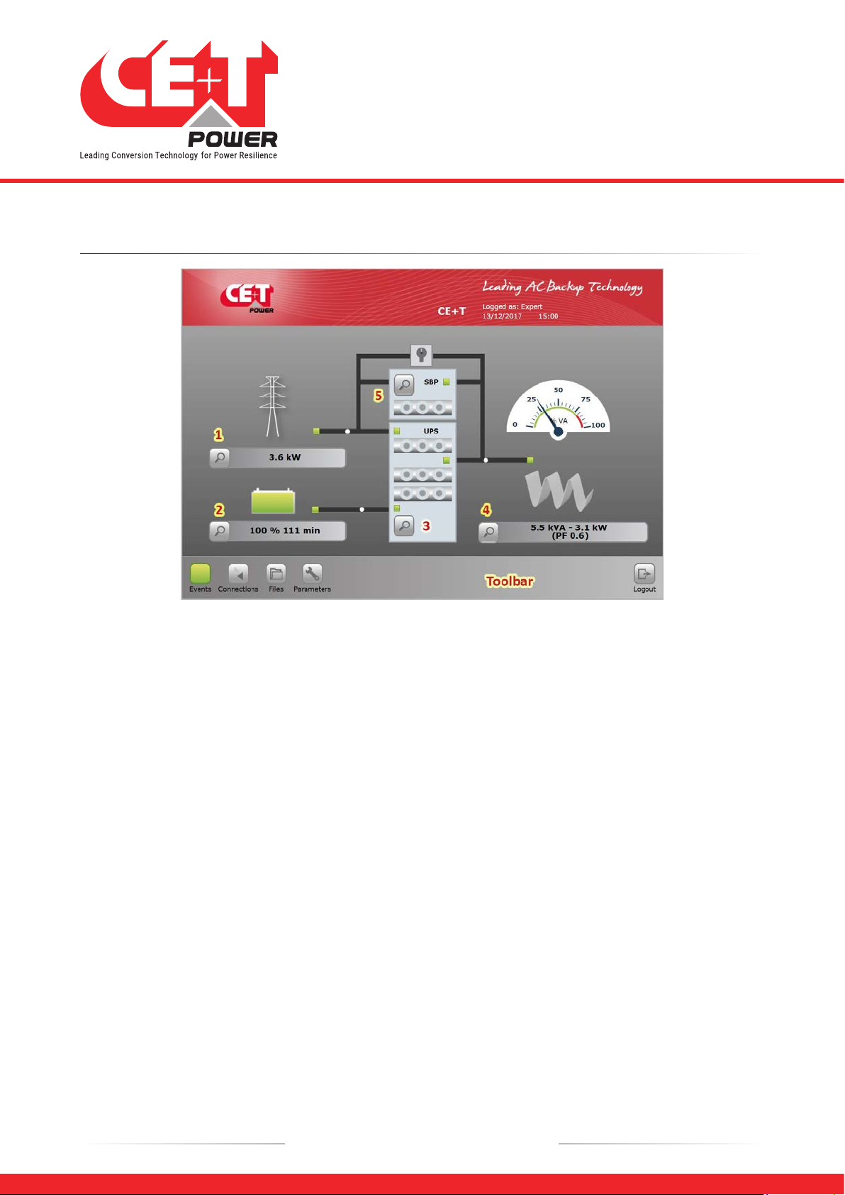
6. Standard Features
The main screen presents an overview of the system where any “click” on the magnifying glass icon will result to
access the selected sub-menu:
1AC Input sub-menu.
2DC Battery sub-menu.
3Flexa Modules sub-menu.
4AC Output load sub-menu.
5SBP Modules sub-menu.
A click on an icon in the toolbar will give you, respectively, access to the event, communication, parameter, files sub-
menu.
The main screen shows the status of each of your power system’s components.
•AC input: Green, Red.
•Battery: Green, Orange, Red.
•Flexa module(s): 3 LEDs (AC input , DC input, AC output).
•AC output / Load: Green, Red.
The energy flow direction is indicated by the “moving” white point on the power lines.

6.1 AC Input Sub-menu
Provides AC input information
(up to 3 phases).
yAC input voltage.
yAC input current.
yAC input Frequency.
yAC input Power (kW).
6.2 DC Battery Sub-menu
Battery x (x = 1 or 2) provide info on
batteries status.
yBOOST ON or OFF
yBattery Test ON or OFF
Estimated autonomy and info on last
test, boost charge, discharge
20 – Flexa 200 - 400/400 – User Manual – v1.0
Standard Features
Table of contents
Other CE+T Power Industrial Equipment manuals

Popular Industrial Equipment manuals by other brands

NEMA
NEMA MG 1-2011 Information guide

Spirax Sarco
Spirax Sarco FTGS14 Installation and maintenance instructions

Pfeiffer Vacuum
Pfeiffer Vacuum PM 061 360-T operating instructions

Bayer HealthCare
Bayer HealthCare RH800 installation guide

Jäger
Jäger Z80-H445.06 S5AW2/2 manual

Timberjack
Timberjack 745 Operator and maintenance manual


werma
werma AndonWirelessBOX quick start guide

Siemens
Siemens SIMATIC NET SCALANCE W1750D Regulatory compliance and safety information guide

Dover
Dover OPW 301 Series Installation and maintenance instructions

HAMAR LASER
HAMAR LASER L-705 manual

schmersal
schmersal AZM201B-I2-CC-T-1P2PW manual

Powrmatic
Powrmatic HEM-NVx Series User, Installation & Servicing Manual