CE+T Power T2S-ETH User manual
Copyright © 2013. Construction electroniques & telecommunications S.A.
All rights reserved. The contents in document are subject to change without notice.
The products presented are protected by several international patents and trademarks.
Address: CE+T S.a, Rue du Charbonnage 12, B 4020 Wandre, Belgium
www.cet-power.com - info@cet-power.com
THE NEW GENERATION OF MONITORING
www.cet-power.com
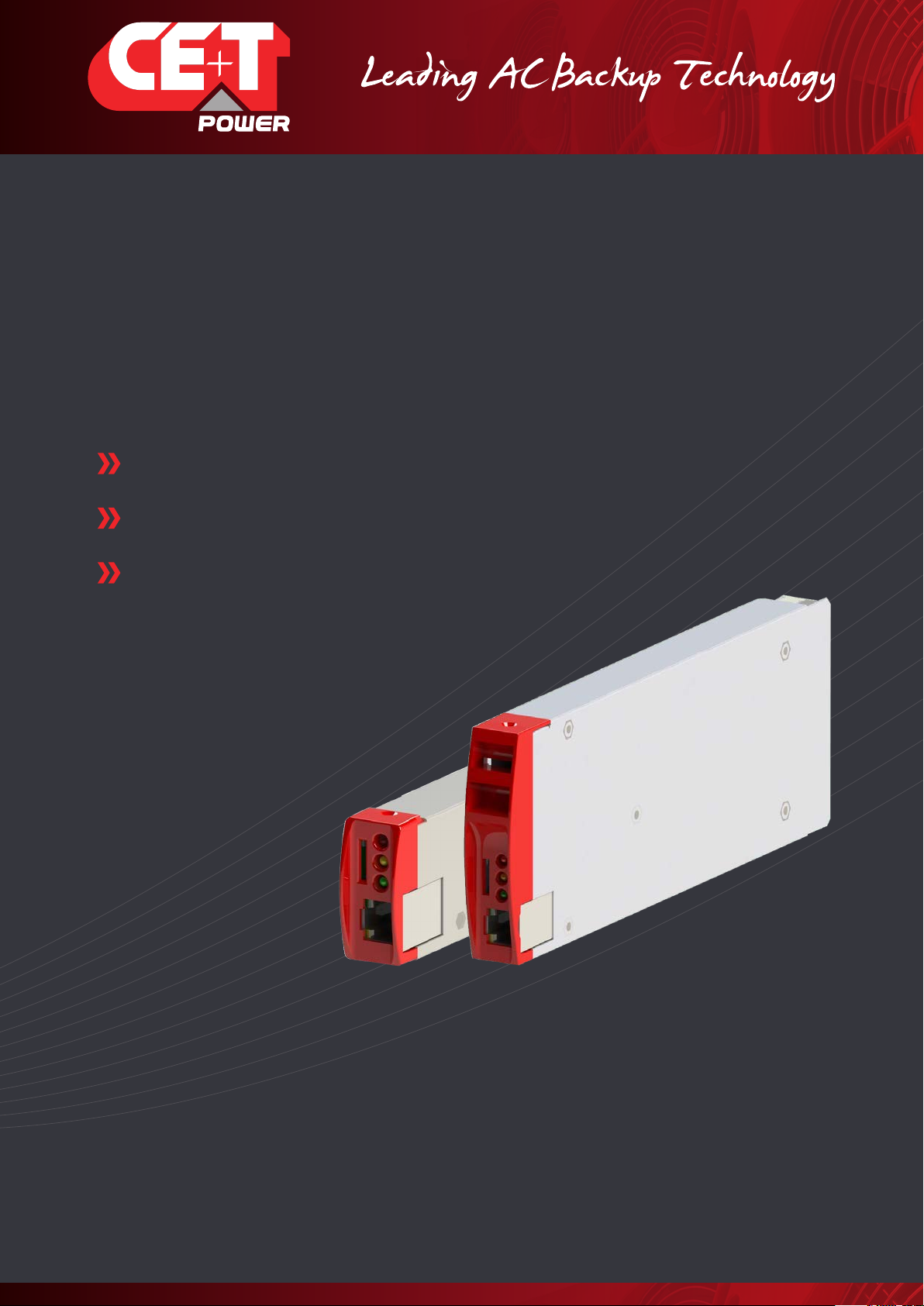
MONITORING T2S - ETH
User Manual V1.4
Web-based User Interface
Extended Log Capabilities
Compatible with Catena
Important Safety Instructions
Save these Instructions

2 – Monitoring T2S - ETH User Manual – v1.4
Table of content
1. CE+T at a glance ................................................................................................................................... 6
2. Abbreviations ........................................................................................................................................ 7
3. Warranty and Safety Conditions ............................................................................................................. 8
3.1 Disclaimer................................................................................................................................... 8
3.2 Technical care............................................................................................................................. 8
3.3 Installation .................................................................................................................................. 9
3.3.1 Handling......................................................................................................................... 9
3.3.2 Surge and transients ...................................................................................................... 9
3.3.3 Other.............................................................................................................................. 9
3.4 Maintenance .............................................................................................................................. 10
3.5 Replacement and Dismantling..................................................................................................... 10
4. Product Code and Identification.............................................................................................................. 11
4.1 Identification labels for T2S-ETH.................................................................................................. 11
5. Introduction ........................................................................................................................................... 12
6. Hardware............................................................................................................................................... 13
6.1 LEDs code during operations....................................................................................................... 14
6.1.1 LEDs code during normal operation................................................................................ 14
6.1.2 LED Error Code - upgrade or system start up.................................................................. 14
6.2 Signaling Information .................................................................................................................. 15
6.2.1 Alarm relay..................................................................................................................... 16
6.2.2 Digital Inputs.................................................................................................................. 16
6.2.3 Communication .............................................................................................................. 16
6.3 Monitoring - Candis..................................................................................................................... 18
6.3.1 Display and Buttons ....................................................................................................... 18
6.3.2 Configuration.................................................................................................................. 18
6.4 Graphical User Interface - Catena................................................................................................ 19
6.4.1 Description..................................................................................................................... 19
6.4.2 Wiring ............................................................................................................................ 20
7. Graphical User Interface......................................................................................................................... 21
7.1 Hierarchy .................................................................................................................................... 21
7.2 Login........................................................................................................................................... 22
7.3 Interface Areas ............................................................................................................................ 22
7.3.1 Banner ........................................................................................................................... 23
7.3.2 Main Area....................................................................................................................... 23
7.3.3 Toolbar........................................................................................................................... 24
7.4 Pages and Feature....................................................................................................................... 25
7.4.1 AC IN.............................................................................................................................. 25
7.4.2 DC IN ............................................................................................................................. 25
7.4.3 AC Out............................................................................................................................ 26
7.4.4 System........................................................................................................................... 26
7.4.5 Module........................................................................................................................... 27

3 – Monitoring T2S - ETH User Manual – v1.4
7.4.6 Events............................................................................................................................ 28
7.4.7 Log ................................................................................................................................ 28
7.4.8 Connections ................................................................................................................... 29
7.4.9 Files ............................................................................................................................... 29
7.4.10 Parameters..................................................................................................................... 30
8. Catena................................................................................................................................................... 39
8.1 Introduction................................................................................................................................. 39
8.2 User interface.............................................................................................................................. 39
8.3 Ethernet connections................................................................................................................... 39
8.3.1 Rear connections............................................................................................................ 39
8.3.2 Front connection ............................................................................................................ 39
8.3.3 Troubleshooting.............................................................................................................. 40
8.4 Configuration............................................................................................................................... 40
8.4.1 Network architecture...................................................................................................... 40
8.5 Protocols..................................................................................................................................... 41
8.5.1 SNMP v2c ...................................................................................................................... 41
8.5.2 SNMP v3 ........................................................................................................................ 41
8.5.3 Modbus over TCP/IP ....................................................................................................... 41
9. SNMP .................................................................................................................................................... 46
9.1 SNMP Configuration .................................................................................................................... 46
9.1.1 Introduction.................................................................................................................... 46
9.1.2 General NMS, SNMP Agent and MIB Role........................................................................ 46
9.1.3 MIB General Design........................................................................................................ 46
9.1.4 SNMP V1 Configuration .................................................................................................. 47
9.1.5 SNMP V2C Configuration ................................................................................................ 49
9.1.6 SNMP V3 Configuration .................................................................................................. 51
9.2 Advanced IP Scanner................................................................................................................... 57
9.3 SNMP V1 Testing ......................................................................................................................... 58
9.4 SNMP V1 Traps............................................................................................................................ 60
9.5 SNMP V3 Testing ......................................................................................................................... 60
9.5.1 Steps to Load CET MIB ................................................................................................... 60
9.5.2 Steps to Discover Device................................................................................................ 62
9.5.3 Steps to Get / Walk OID .................................................................................................. 63
9.5.4 Steps to Add SNMP V3 User............................................................................................ 63
10. FAQ....................................................................................................................................................... 65
11. Trouble Shooting and Defective Situations Fixing.................................................................................... 66
11.1 Defective T2S ETH....................................................................................................................... 66
11.1.1 Return defective T2S interface ....................................................................................... 66
11.1.2 Return defective T2S ETH............................................................................................... 66

4 – Monitoring T2S - ETH User Manual – v1.4
12. Service ................................................................................................................................................. 67
13. Maintenance Task .................................................................................................................................. 68
14. Annex 1: Supervisor alarms - T2S ETH .................................................................................................. 69
15. Annex 2: Module alarms - T2S ETH ....................................................................................................... 72
16. Annex 3: Modbus .................................................................................................................................. 77
16.1 Hardware Requirements.............................................................................................................. 77
16.1.1 Cabling:.......................................................................................................................... 77
16.1.2 Baud rate, parity and mode ............................................................................................ 77
16.2 Database Description ................................................................................................................. 78
16.2.1 Typographic convention:................................................................................................. 78
16.2.2 Data types:..................................................................................................................... 78
16.2.3 Supported function:........................................................................................................ 78
16.3 Status and Constants Description ................................................................................................ 84
16.3.1 Module status explanation (A1):...................................................................................... 84
16.3.2 Alarm types:................................................................................................................... 84
16.3.3 Alarm sources: ............................................................................................................... 85
16.3.4 Validity and Unit description (A2):.................................................................................... 85
16.4 Examples .................................................................................................................................... 86
16.4.1 Introduction.................................................................................................................... 86
16.5 Modbus Testing ........................................................................................................................... 90
16.5.1 Requirement:.................................................................................................................. 90
16.5.2 Modbus Testing procedure ............................................................................................. 91

Release Note:
Version Release date
(DD/MM/YYYY)
Modified page
number Modifications
1.0 11/04/2016 - First release of the manual.
1.1 27/01/2017 17, 32 and 39 Catena and SNMP details updated.
46 Added Annex.
1.2 18/09/2017 42 - 47 Modbus Testing Procedure.
1.3 10/08/2018 - Added SNMP Details.
1.4 03/10/2018 76 Updated Modbus details.
5 – Monitoring T2S - ETH User Manual – v1.4

1. CE+T at a glance
CE+T Power designs, manufactures and markets a range of products for industrial operators with mission critical
applications, who are not satisfied with existing AC backup systems performances, and related maintenance costs.
Our product is an innovative AC backup solution that unlike most used UPS’s
•Maximizes the operator’s applications uptime;
•Operates with lowest OPEX;
•Provides best protection to disturbances;
•Optimizes footprint.
Our systems are:
•Modular
•Truly redundant
•Highly efficient
•Maintenance free
•Battery friendly
CE+T power puts 60+ years expertise in power conversion together with worldwide presence to provide customized
solutions and extended service 24/7 - 365 days per year.
6 – Monitoring T2S - ETH User Manual – v1.4
CE+T at a glance
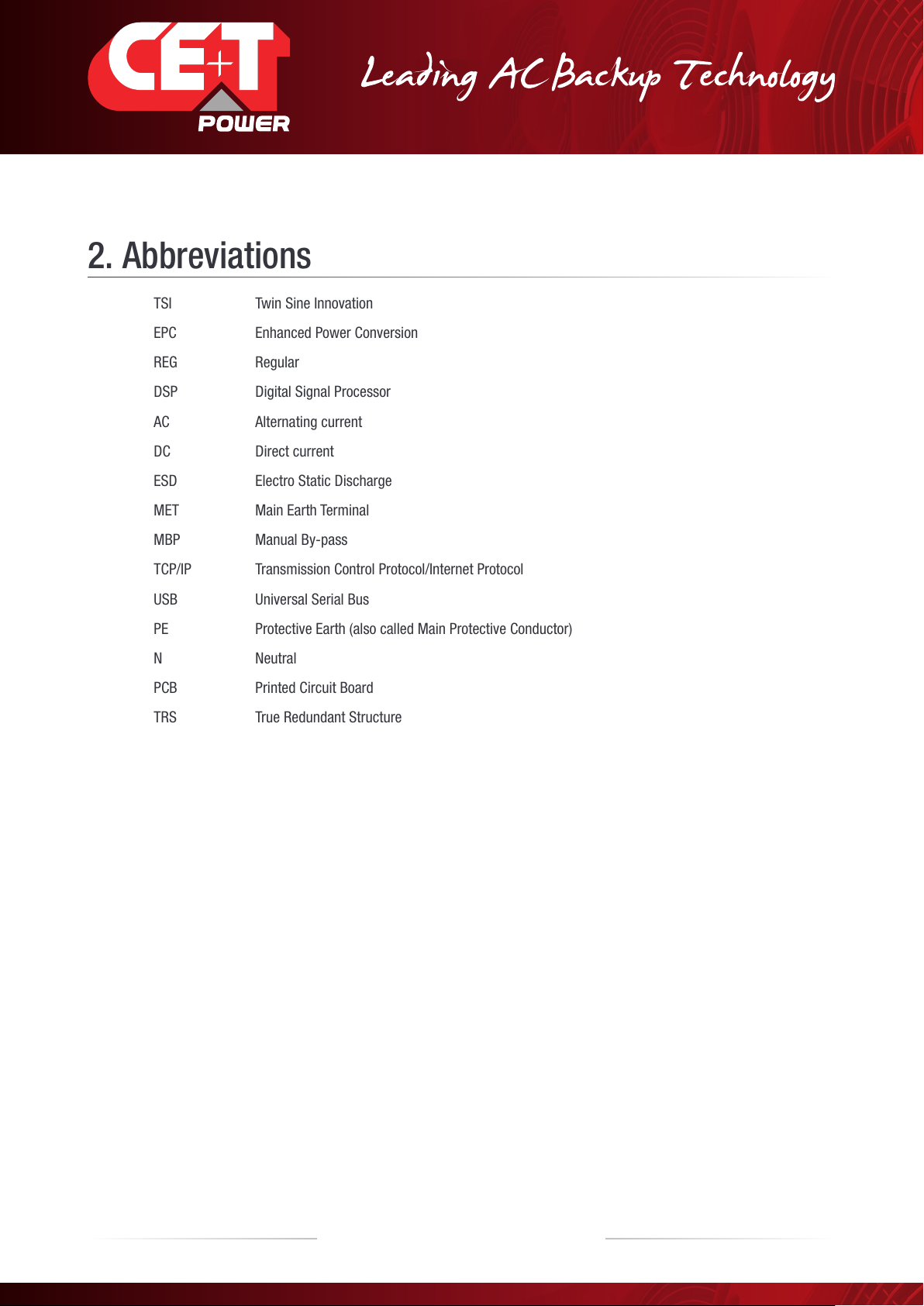
2. Abbreviations
TSI Twin Sine Innovation
EPC Enhanced Power Conversion
REG Regular
DSP Digital Signal Processor
AC Alternating current
DC Direct current
ESD Electro Static Discharge
MET Main Earth Terminal
MBP Manual By-pass
TCP/IP Transmission Control Protocol/Internet Protocol
USB Universal Serial Bus
PE Protective Earth (also called Main Protective Conductor)
N Neutral
PCB Printed Circuit Board
TRS True Redundant Structure
7 – Monitoring T2S - ETH User Manual – v1.4
Abbreviations
3. Warranty and Safety Conditions*
WARNING:
The electronics in the power supply system are designed for an indoor, clean environment.
When installed in a dusty and/or corrosive environment, outdoor or indoor, it is important to:
•Install an appropriate filter on the enclosure door, or on the room’s air conditioning system.
•Keep the enclosure door closed during operation.
•Replace the filters on a regular basis.
Important Safety Instructions, Save These Instructions.
3.1 Disclaimer
•The manufacturer declines all responsibilities if equipment is not installed, used or operated according to the
instructions herein by skilled technicians according to local regulations.
•Warranty does not apply if the product is not installed, used and handled according to the instructions in the
manuals.
3.2 Technical care
•This electric equipment can only be repaired or maintained by a “qualified employee” with adequate training.
Even personnel who are in charge of simple repairs or maintenance are required to have knowledge or
experience related to electrical maintenance.
•Please follow the procedures contained in this Manual, and note all the “DANGER”, “WARNING” AND “NOTICE”
marks contained in this Manual. Warning labels must not be removed.
•Qualified employees are trained to recognize and avoid any dangers that might be present when working on or
near exposed electrical parts.
•Qualified employees understand how to lock out and tag out machines so the machines will not accidentally be
turned on and injure employees working on them.
•Qualified employees also understand safety related work practices, including those by OSHA and NFPA, as well
as knowing what personal protective equipment should be worn.
•All operators are to be trained to perform the emergency shut-down procedure.
•Never wear metallic objects such as rings, watches, or bracelets during installation, service and maintenance of
the product.
•Insulated tools must be used at all times when working with live systems.
•When handling the system/units pay attention to sharp edges.
* These instructions are valid for most CE+T Products/Systems. Some points might however not be valid for the
product described in this manual
8 – Monitoring T2S - ETH User Manual – v1.4
Warranty and Safety Conditions
3.3 Installation
•This product is intended to be installed only in restricted access areas as defined by UL60950 and in accordance
with the National Electric Code, ANSI/NFPA 70, or equivalent agencies.
•The Inverter System may contain output over current protection in the form of circuit breakers. In addition to
these circuit breakers, the user must observe the recommended UL listed upstream and downstream circuit
breaker requirements as defined in this manual.
•Please use extreme caution when accessing circuits that may be at hazardous voltages or energy levels.
•The modular inverter rack is a dual input power supply. The complete system shall be wired in a way that both
input and output leads can be made power free.
•REG systems and EPC systems that have no AC input wired and connected can be seen as independent power
sources. To comply with local and international safety standards N (output) and PE shall be bonded. The bonded
connection between N (output) and PE must be removed once the AC input is connected.
•AC and DC circuits shall be terminated with no voltage / power applied.
•The safety standard IEC/EN62040-1-1 requires that, in the event of an output short circuit, the inverter must
disconnect in 5 seconds maximum. The parameter can be adjusted on T2S; however, if the parameter is set at a
value > 5 seconds, an external protection must be provided so that the short circuit protection operates within 5
seconds.
Default setting is 60 seconds.
•The system is designed for installation within an IP20 or IP21 environment. When installed in a dusty or humid
environment, appropriate measures (air filtering …) must be taken.
3.3.1 Handling
•The cabinet shall not be lifted using lifting eyes.
•Remove weight from the cabinet by unplugging the inverters. Mark inverters clearly with shelf and position for
correct rebuild. This is especially important in dual or three phase configurations.
•Empty inverter positions must not be left open. Replace with module or cover.
3.3.2 Surge and transients
The mains (AC) supply of the modular inverter system shall be fitted with Lightning surge suppression and Transient
voltage surge suppression suitable for the application at hand. Manufacturer’s recommendations of installation shall
be adhered to. Selecting a device with an alarm relay for function failure is advised.
Indoor sites are considered to have a working lightning surge suppression device in service.
•Indoor sites Min Class II.
•Outdoor sites Min Class I + Class II or combined Class I+II. The modular inverter system/rack can reach
hazardous leakage currents. Earthing must be carried out prior to energizing the system. Earthing shall be made
according to local regulations.
3.3.3Other
•Isolation test (Hi-Pot) must not be performed without instructions from the manufacturer.
9 – Monitoring T2S - ETH User Manual – v1.4
Warranty and Safety Conditions
3.4 Maintenance
•The modular inverter system/rack can reach hazardous leakage currents. Earthing must be carried out prior to
energizing the system. Earthing shall be made according to local regulations.
•Prior to any work conducted on a system/unit make sure that AC input voltage and DC input voltage are
disconnected.
•Inverter modules and shelves contain capacitors for filtering and energy storage. Prior to accessing the system/
modules after power down, wait at least 5 minutes to allow capacitors to discharge.
•Some components and terminals carry high voltage during operation. Contact may result in fatal injury.
3.5 Replacement and Dismantling
•ESD Strap must be worn when handling PCBs and open units.
•CE+T cannot be held responsible for disposal of the Inverter system and therefore the customer must segregate
and dispose of the materials which are potentially harmful to the environment, in accordance with the local
regulations in force in the country of installation.
•If the equipment is dismantled, to dispose of its component products, you must comply with the local regulations
in force in the country of destination and in any case avoid causing any kind of pollution.
To download the latest documentation and software, please visit our website at
www.cet-power.com
10 – Monitoring T2S - ETH User Manual – v1.4
Warranty and Safety Conditions
11 – Monitoring T2S - ETH User Manual – v1.4
Product Code and Identification
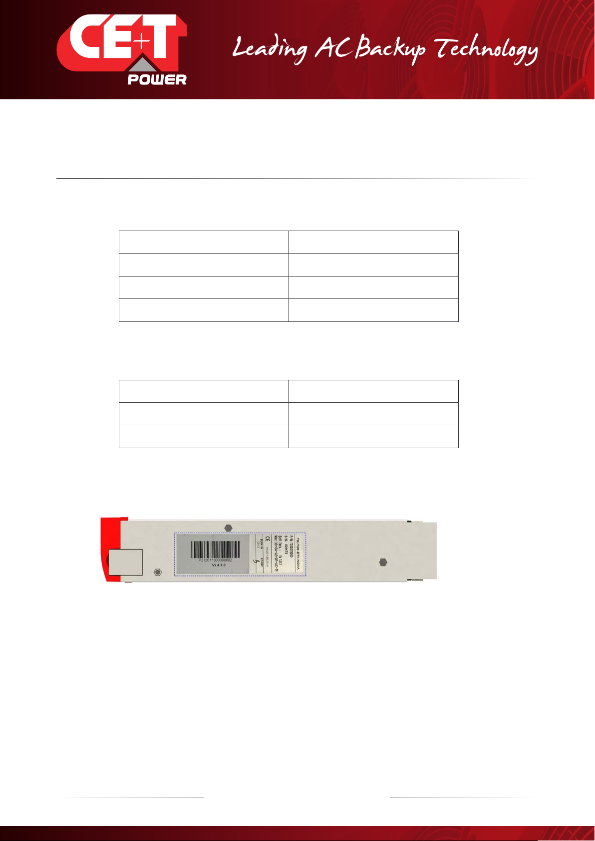
4. Product Code and Identication
T2S-ETH product code with regards to sub rack:
A) T2S-ETH Monitor
Product Description Part Number
TSI-T2S-ETH-NOVA - VEDA T312010010
TSI-T2S-ETH-BRAVO-MEDIA 24/48/60 Vdc T322010100
TSI-T2S-ETH-BRAVO-MEDIA 110/220 Vdc T322051000
B) Filler (Blank module to cover empty slots)
Product Description Part Number
TSI-T2S-ETH-NOVA - VEDA T312010010
BLANK PLASTIC T2S ETH ECI RED T522010001
4.1 Identication labels for T2S-ETH
Note:
The PART NUMBER, SERIAL NUMBER and BURN IN DATE are essential information when you contact CE+T to get help
in commissioning or in troubles or when item is sent back for repair.

12 – Monitoring T2S - ETH User Manual – v1.4
Introduction
5. Introduction
The T2S ETH stands for T2S Ethernet. It replaces the former T2S with the same form factor but with a front Ethernet
connector replacing the former USB one. Like his predecessor, T2S ETH is a monitoring solution for the full TSI inverter
range and is able to monitor up to 32 inverters through a friendly web base interface. T2S also supports Modbus Serial
communication (RTU) and SNMP v1 Communication.
This new monitoring device provides a graphical user interface, embeds a SNMPv2c/SNMP v3 agent and Modbus TCP
support with Catena, if one needs a touch screen display Catena can be connected to T2S ETH and is Compatible. It
also allows user to change the configuration of the system.

13 – Monitoring T2S - ETH User Manual – v1.4
Hardware
6. Hardware
T2S ETH provides 3 LEDs: Red for major alarm signaling, orange led for minor alarm signaling and green led for power
and network connection status.
The RJ45 is a standard ETH connector that could be connected on any IPv4 network.
T2S ETH firmware can be upgrade using the Micro SD card. Device firmwares are available in my.cet-power.com
14 – Monitoring T2S - ETH User Manual – v1.4
Hardware
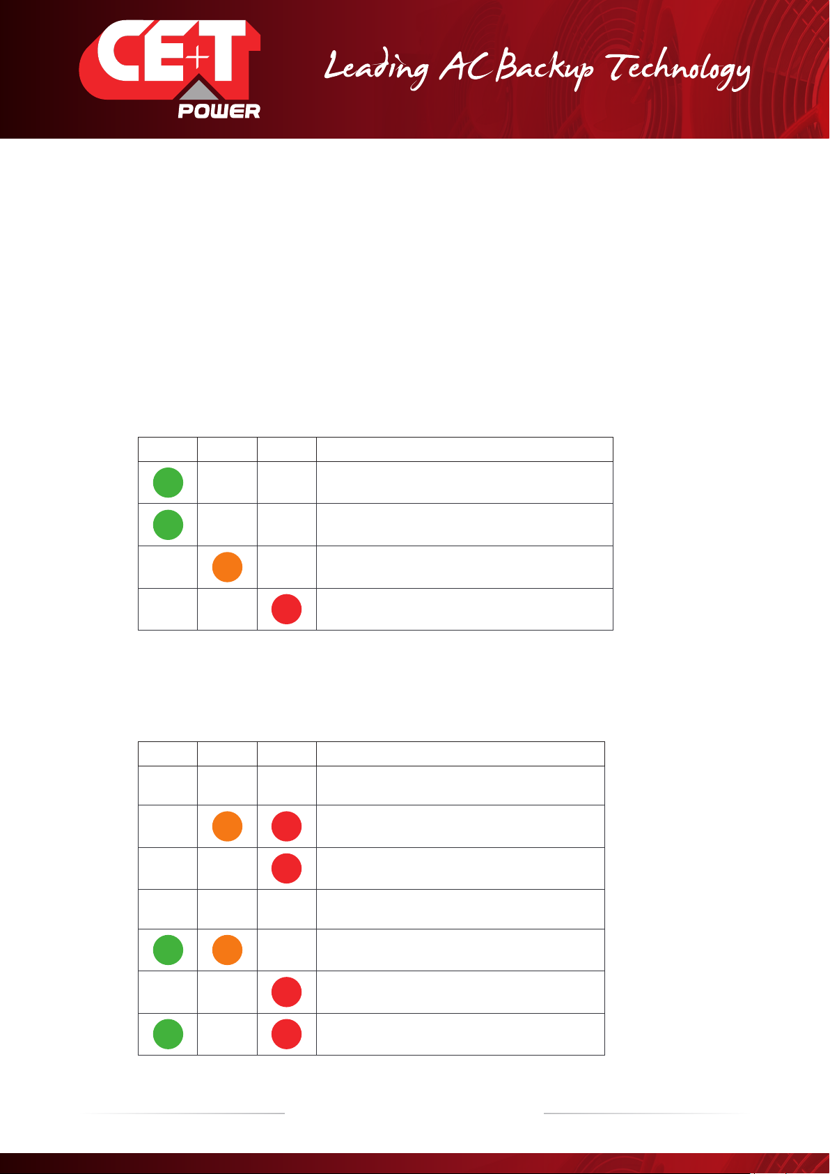
6.1 LEDs code during operations
S - Flash low
FS - Flash fast
SA - Sequence one after the other
X - Not used LED
6.1.1 LEDs code during normal operation
LEDs code below corresponds to system in operation and T2S ETH fully operational.
Green Orange Red Status
SSlave mode (when several T2S ETH on the same bus)
Master Mode « master »
Minor alarm / Alarme Mineure
Major alarm / Alarme Majeure
6.1.2 LED Error Code - upgrade or system start up
This section explains the state of the boot loader in function of his LED state. During start up, soft upgrade,
configuration change or micro SD card changes.
Green Orange Red Status
Booting
Cannot copy to flash
FS No micro SD card or file *.bcf not valid or not present
File *.acf found
SA SA Installation *.saf please wait
FS System error or no micro SD card
SFS Configuration.ini found waiting network
15 – Monitoring T2S - ETH User Manual – v1.4
Hardware
Green Orange Red Status
FS Boot loader Web interface ON and in operation
SFS System file OK but no config file *.ini
S S S Error SD Card / File
S S Error no configuration.ini
6.2 Signaling Information
As it is designed to be used in the same shelf as former T2S, T2S ETH inherits the connections on the back.
Note: The terminal connector accepts maximum wire size of 0.5 mm2.
Important remarks:
In a system with several shelves, T2S ETH is usually located in the first one (although it’s not mandatory) but relay
signaling contacts will be terminated in the T2S ETH installed shelf. The above connection is just an example, actual
connection will be based on your shelf design and connections.
If the T2S is included in one complete system including for example Termination box or some customers packages, the
terminal will be located somewhere else. (Refer System user manual).

16 – Monitoring T2S - ETH User Manual – v1.4
Hardware
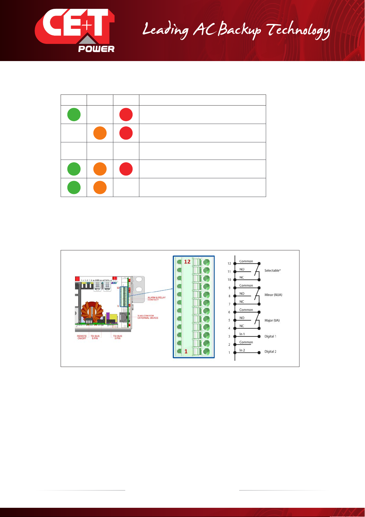
6.2.1 Alarm relay
There are 3 alarm contacts:
•Major
•Minor
•User selectable
As one can see in the picture: contacts 5 and 6 are closed when no major alarm is present,
contact 8 and 9 are closed when no minor alarm is present.
Remark: Default mapping and level of each available alarm of the monitoring unit is
available in “Annex 1: Supervisor alarms - T2S ETH”, page 69.
NB: Alarm relay are active (energized) when no alarm are present.
•Alarms relay features
Max current: 2 A @ 30 VDC or 1A @ 60 VDC
Max Power: 60 W
Max Voltage: 60 VDC SELV
Note that for higher voltages, it is mandatory to install an additional relay with appropriate characteristics – especially
for 60/110/220 VDC.
6.2.2 Digital Inputs
Two potential free Digital inputs are available for customer connections.
•Digital Input 1 is assigned for MBP operation if used.
•Digital Input 2 is assigned for Surge Arrester if used.
The voltage present on terminal 1 and 3 is +5 V (galvanic insulation). Care should be taken to avoid connecting any
external voltage on terminal 1 to 3. External signals should be applied to these terminals via Volt-free contacts. The
function is activated when the 2 terminals concerned are short-circuited (i.e. when the external Volt-free contact is
closed).
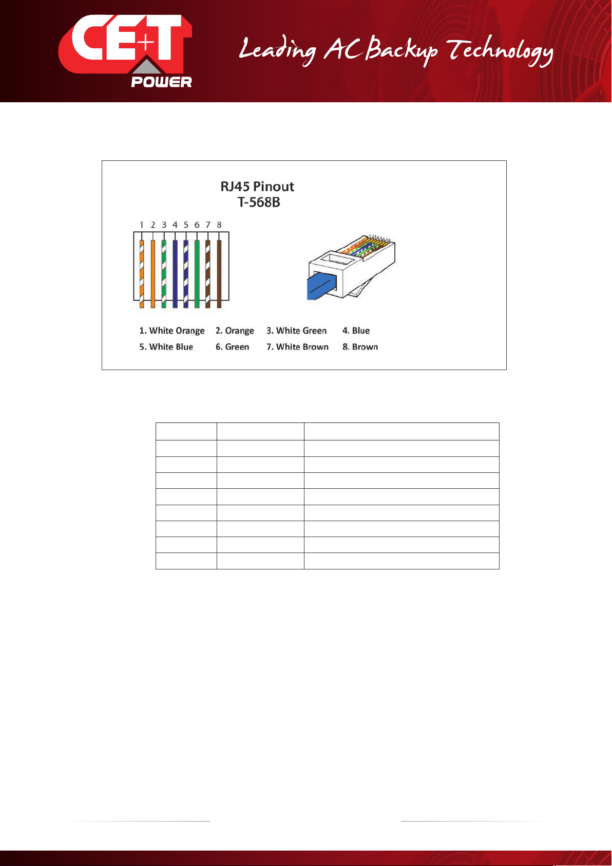
6.2.3 Communication
A RJ45 connector is present at rear of the shelf and can be used for Candis display and Modbus (RTU) communication.
17 – Monitoring T2S - ETH User Manual – v1.4
Hardware
Note: The colour of wires is irrelevant and may vary, but make sure the position of wires is exactly crimped.
Pin Number Name Description
1 CANH CANH pin for Candis
2 CANL CANL pin for Candis
3 GND_IAX Digital Communication Ground
4 GND_IAX Digital Communication Ground
5 12V_IAX +12 V unregulated
6 COM_A RS 485 A
7 GND_IAX Digital Communication Ground
8 COM_B RS 485 B
Important remark:
T2S ETH comes in only one “flavor” in term of serial communication RS485 and support Modbus RTU (read-only).
Currently, no protocol is available for customer use on CAN bus connection and it is dedicated for Candis accessory.
The unregulated +12 V power supply is designed for powering CE+T accessories and should not be used for any other
purpose.
18 – Monitoring T2S - ETH User Manual – v1.4
Hardware
6.3 Monitoring - Candis
T2S ETH also supports the Candis display and it is a monitoring device allowing the user to get
information from inverter system.
To enable candis, connect RJ45 CAT cable at rear side of the T2S ETH installed shelf and
Candis. Refer section 6.2.3, page 16.
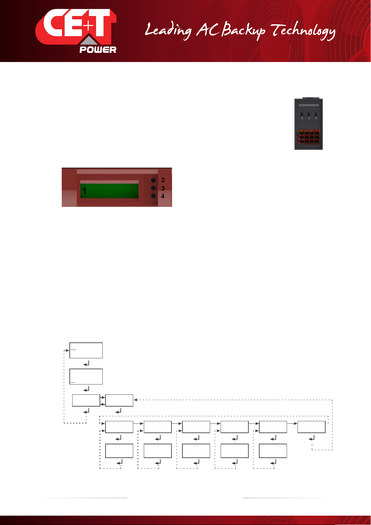
6.3.1 Display and Buttons
1 Display (2 lines provided to display information).
2 Up button to scroll UP in the menus.
3 Down button to scroll DOWN in the menus.
4 Enter button to change display or validate modifications.
6.3.2 Conguration
When more than one display is used on the same system, the CANBUS ID must be different and include values from
124 to 264 (i.e as 134; 144 ; 154, …264).
The other information that can be configured are the related phase, the AC group or DC group, and the adjustment the
backlight.
If the installed system is multi-phase or has multiple DC groups, the T2S and the inverter modules must be correctly
configured to display the correct value by phase or DC group.
For instance in three phase systems, the inverter modules must be configured to show the 3 phases’ output
information, but also the one related to the three AC group who correspond to each AC input phase. By doing so, the
display will show the values phase by phase.
Warning: The Candis Display is powered from the auxiliary power supply of the modules which are
limited in power.
V out= 233 V
I out= 3 A
V out= 233 V
I out= 3 A
Main Menu
Disp Param Config
DC Group :AC Group :Phase Sel :
Back lt +/- ID CAN +/-
0124
Phase +/-
0001
AC grp +/-
0001
DC grp +/-
0001
CAN BUS IDBacklight
The line beneath the first line indicates that
display parameters can be changed for first line.
The line beneath the second line indicates that
display parameters can be changed for second line.
Candis Display - Block diagram
TSI System with Candis
19 – Monitoring T2S - ETH User Manual – v1.4
Hardware
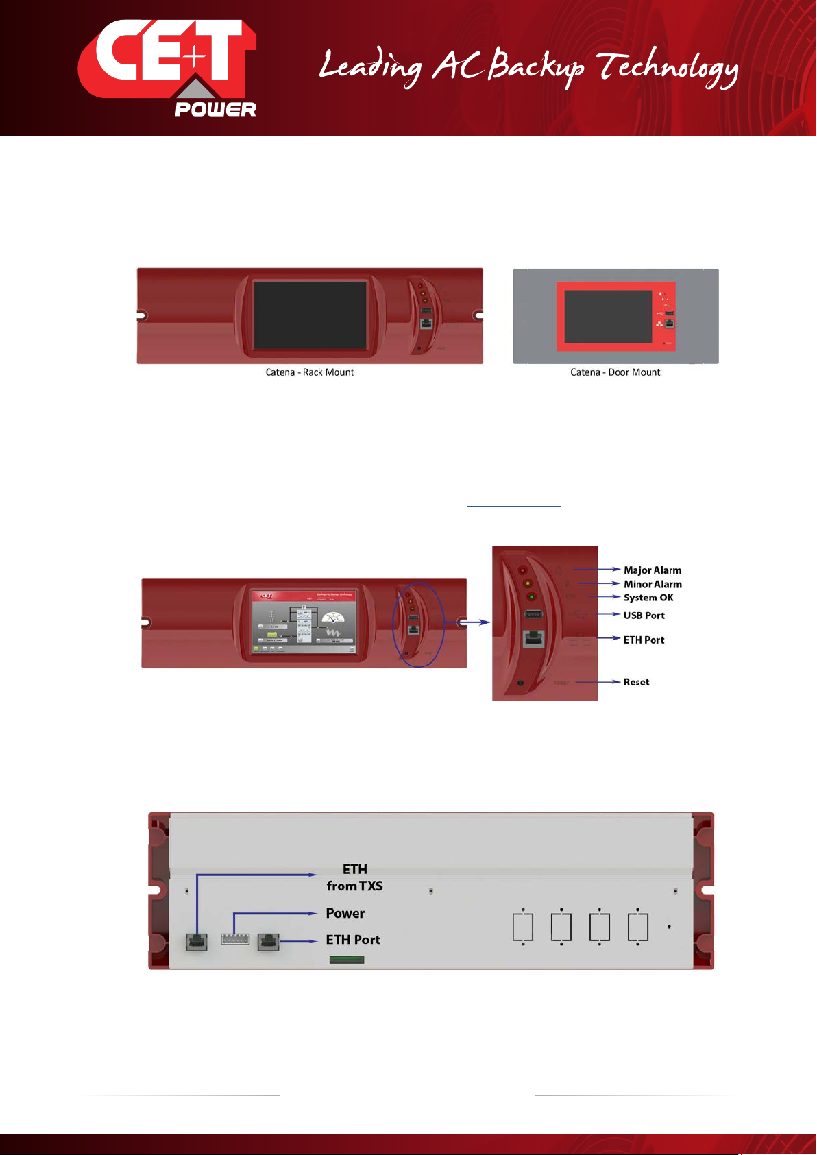
6.4 Graphical User Interface - Catena
The Catena display can be used with the T2S ETH. Catena is either available in rack mount or door mount version.
6.4.1 Description
On front access, Catena has a wide 7’’ capacitive touch screen alongside 3 led following the same scheme as in T2S
ETH and two connectors: USB type A and Ethernet (RJ45). A reset button is also provided. Catena firmware can be
upgrade using the Micro SD card. Device firmware is available in my.cet-power.com
From the rear, there are two 12 VDC inputs that help Catena to be powered by two different sources, usually AC and
DC. The PE is also available on power supply connector. Two Ethernet (RJ45) ports are available, one for connection to
T2S ETH (see section 6.4.2, page 20) and one for permanent network connection.
Important remark: this is the latest version released of Catena. If you have different version of
Catena, refer to the system user manual.
20 – Monitoring T2S - ETH User Manual – v1.4
Hardware
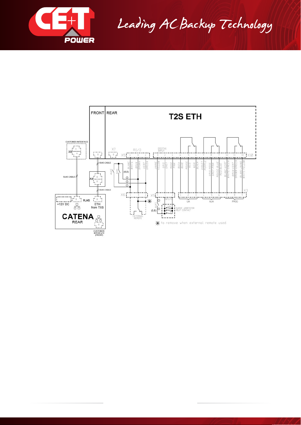
6.4.2 Wiring
Catena configuration has to be selected in T2S ETH under monitoring, network, connection mode, hardware setup
should be With Catena. This option has to be selected even before wiring.
Table of contents
Other CE+T Power Industrial Equipment manuals

Popular Industrial Equipment manuals by other brands

Rice Lake
Rice Lake 1280 Enterprise Series quick start guide

Schleuniger
Schleuniger PreFeeder 1100 manual

Veeco
Veeco Mark II Technical manual

CIAS Elettronica S.r.l.
CIAS Elettronica S.r.l. CORAL-PLUS Installation handbook

Nordson
Nordson Rhino VE quick start guide

Mathey Dearman
Mathey Dearman 01.0505.R06 Parts and Operating Manual


Emerson
Emerson Rosemount 3051S Series quick start guide

Rohde & Schwarz
Rohde & Schwarz FS-SNS18 manual

Endress+Hauser
Endress+Hauser Cleanfit CPA871 operating instructions

Mec
Mec 500E DOUBLES ATA owner's manual

Code Blue
Code Blue CB RT Series Admin guide

Minebea Intec
Minebea Intec PR 54 installation manual