manuals.online logo
Brands
  1. Home
  2. •
  3. Brands
  4. •
  5. Cessna
  6. •
  7. Aircraft
  8. •
  9. Cessna Skyhawk 1970 User manual

Cessna Skyhawk 1970 User manual

CESSNA
MORE PEOPLE BUY AND
FLY CESSNA AlRPLANES
THAN ANY OTHER MAKE
1970 '
SINAWK
WU CRLE
DR
'5 OLFARNE SNER A° OWNE R' S
AVIATION AIRCRAFT
51NCE 1956 MANUAL
PERFORMANCE -SPEClFICATIONS
Model172* Skyhawk*
GROSS WEIGHT ..... . ... .. . . . 2300 lbs 2300 lbs
SPEED:
Top Speed at Sea Level ..... . .. . 139 mph 140 mph
Cruise, 759'oPower at 9000 ft .. . . . .131 mph 132 mph
RANGE:
Cruise, 75°/oPower at 9000 ft .. . -.-615 mi 620 mi
38 Gal., No Reserve 4.7 hrs 4.7 hrs
131 mph 132 mph
Cruise, 75/o Power at 9000 ft .. . . 775 mi 780 mi
48 Gal., No Reserve 5.9 hrs 5.9 hrs
131 mph 132 mph
Optimum Range at 10, 000 ft . . ....-640 mi 655 mi
38 Gal., No Reserve 5.5 hrs 5.5 hrs
117 mph 118 mph
Optimum Range at 10, 000 ft ..... . . 820 mi 830 mi
48 Gal., No Reserve 7.0 hrs 7.0 hrs
117 mph 118 mph
RATE OF CLIMB AT SEA LEVEL .. . --.645 fpm 645 fpm
SERVICE CEILING .. . ......... . 13, 100 ft 13, 100 ft
TAKE-OFF:
GroundRun .............. 865ft 865ft
Total Distance Over 50-Foot Obstacle. . . 1525 ft 1525 ft
LANDING:
GroundRoll.............. 520ft 520ft
Total Distance Over 50-Foot Obstacle. . - 1250 ft 1250 ft
STALL SPEED:
Flaps Up, Power Off . . . . .... .- 57 mph 57 mph
Flaps Down, Power Off ... . . . . - - 49 mph 49 mph
EMPTY WEIGHT (Approximate) . . .. . . . 1245 lbs 1315 lbs
USEFUL LOAD . . . . . .. . ... ....1055 lbs 985 lbs
BAGGAGE .... . .. . ... ... .. - 120 lbs 120 lbs
WING LOADING: Pounds/Sq Foot .-...-13. 213. 2
POWER LOADING: Pounds/HP .. . . . . . 15. 315. 3
FUEL CAPACITY: Total
Standard Tanks .... . . . . . .--42 gal. 42 gal.
Optional Long Range Tanks ... . .- - 52 gal. 52 gal.
OIL CAPACITY: Total .. . ... . . . . . 8 qts 8 qts
PROPELLER: Fixed Pitch (Diameter) ... - 76 inches 76 inches
ENGINE:
Lycoming Engine -- - - - - - -----O-320-E2D O-320-E2D
150 rated HP at 2700 RPM
*This manual covers operation of the Model 112/Skyhawk which is certificated
as Model 172K under FAAType Certificate No. 3Al2.
D742-13-RAND-T500-10/73
CONGRATULATIONS . . . . . . .
Welcome to the ranks of Cessna owners! Your Cessna has been designed
and constructed to give you the most in performance, economy, and com-
fort. It is our desire that you will find flying it, either for business or
pleasure, apleasant and profitable experience.
This Owner's Manual has been prepared as a guide to help you get the
most pleasure and utility from your Model 172/Skyhawk. It contains in-
formation about your Cessna's equipment, operating procedures, and per-
formance; and suggestions for its servicing and care. We urge you to read
it from cover to cover, and to refer to it frequently.
Our interest in your flying pleasure has not ceased with your purchase of
a Cessna. World-wide, the Cessna Dealer Organization backed by the
Cessna Service Department stands ready to serve you. The following
services are offered by most Cessna Dealers:
FACTORY TRAINED PERSONNEL to provide you with courteous
expert service.
FACTORY APPROVED SERVICE EQUIPMENT to provide you
with the most efficient and accurate workmanship possible.
ASTOCK OF GENUINE CESSNA SERVICE PARTS on hand
when you need them.
THE LATEST AUTHORITATIVE INFORMATION FOR SERV-
ICING CESSNA AIRPLANES, since Cessna Dealers have all
of the Service Manuals and Parts Catalogs, kept current by
Service Letters and Service News Letters, published by Cessna
Aircraft Company.
We urge all Cessna owners to use the Cessna Dealer Organization to the
fullest.
Acurrent Cessna Dealer Directory accompanies your new airplane. The
Directory is revised frequently, and a current copy can be obtained from
your Cessna Dealer. Make your Directory one of your cross-country
flight planning aids; awarm welcome awaits you at every Cessna Dealer.
i
8-9½" MAX.
2-11"
1154"
iMaximum height of airplane
with nose gear depressed and
an optional flashing beacon
installed.
PRINCIPAL
DIMENSIONS
35
-4" MAX
7 2"-
ii
TABLE OF CONTENTS
Page =
SECTION I-OPERATING CHECK LIST .....___ 1-1
SECTION 11 -DESCRIPTION AND
OPERATING DETAILS ..........___ 2-1
SECTION lli -EMERGENCY PROCEDURES..... 3-1
SECTION IV -OPERATING LIMITATIONS........ 4-1
SECTION V-CARE OF THE AIRPLANE........ 5-1
OWNER FOLLOW-UP SYSTEM --------------- 5-10
SECTION VI -OPERATIONAL DATA......-____... 6-1
SECTION VII- OPTIONAL SYSTEMS......-....... 7-1
ALPHABETICAL INDEX........................... Index-1
This manual describes the operation and performance of
both the Cessna Model 172 and Skyhawk. Equipment des -
cribed as "Optional" denotes that the subject equipment is
optional on the Model 172. Much of this equipment is stan-
dard on the Skyhawk model.
iii
EXTERIOR Note
S
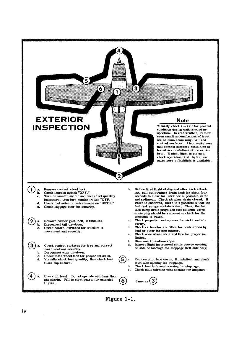
CTIOIN PE NVisuaHy check aircraft for general
condition during walk-around in-
spection. In cold weather, remove
even sman accumulations of frost,
ice or snow from wing, tail and
control surfaces. Also, make sure
that control surfaces contain no in-
ternal accumulations of ice or de-
bris. 11 night flight is planned,
check operation of all lights, and
make sure a flashlight is available.
2
a. Remove control wheel lock. b. Before first flight of day and after each refuel-
b. Check ignition switch "OFF." ing, pull out strainer drain knob for about four
c. Turn on master switch and check fuel quantity seconds to clear fuel strainer of possible water
indicators, then tura master switch "OFF." and sediment. Check strainer drain closed. If
d. Check fuel selector valve hamile on "BOTH." water is observed, there is a possibility that the
e. Check baggage door for security, fuel tank sumps contain water. Thus, the fuel
tank sump drain plugs and fuel selector valve
drain plug should be removed to check for the
presence of water.
a. Remove rudder gust lock, if installed. c. Check propeller and spinner for nicks and se-
b. Disconnect tall tie-down. curity.
c. Check control surfaces for freedom of d. Check carburetor air filter for restrictions by
movement and security, dust or other foreign matter.
e. Check nose wheel strut and tire for proper in-
flation.
f. Disconnect tie-down rope.
a. Check control surfaces for free and correct g. Inspect flight instrument static source opening
movement and security. on side of fuselage for stoppage (left side only).
b. Disconnect wing tie-down,
c. Check main wheel tire for proper inflation.
d. Visually check fuel quantity, then check fuel a. Remove pitot tube cover, if installed, and check
filler cap secure, pitot tube opening for stoppage,
b. Check fuel tank vent opening for stoppage,
c. Check sta11 warning vent opening for stoppage.
a. Check oil level. Do not operate with less than
xq ts. Fill to eight quarts for extended Same as
Figure 1-1.
iv
Jecties I
OPERATING CHECK LIST
One of the first steps in obtaining the utmost performance, service,
and flying enjoyment from your Cessna is to familiarize yourself with
your airplane's equipment, systems, and controls. This can best be done
by reviewing this equipment while sitting in the airplane. Those items
whose function and operation are not obvious are covered in Section II.
Section I lists, in Pilot's Check List form, the steps necessary to
operate your airplane efficiently and safely. It is not a check list in its
true form as it is considerably longer, but it does cover briefly all of
the points that you should know for a typical flight.
The flight and operational characteristics of your airplane are normal
in all respects. There are no "unconventional" characteristics or opera-
tions that need to be mastered. All controls respond in the normal way
within the entire range of operation. All airspeeds mentioned in Sections
I, II and HI are indicated airspeeds. Corresponding calibrated airspeed
may be obtained from the Airspeed Correction Table in Section VI.
BEFORE ENTERING THE AIRPLANE.
(1) Make an exterior inspection in accordance with figure 1-1.
BEFORE STARflNG THE ENGINE.
(1) Seats and Seat Belts -- Adjust and lock.
(2) Fuel Selector Valve -- "BOTH."
(3) Brakes -- Test and set.
(4) Radios and Electrical Equipment -- "OFF."
1-1
STARTING THE ENGINE.
(1) Mixture -- Rich.
(2) Carburetor Heat -- Cold.
(3) Primer -- 2-6strokes (as required; none if engine is warm)
Close and lock primer.
(4) Throttle -- Open 1/8".
(5) Master Switch -- "ON. "
(6) Propeller Area -- Clear.
(7) Ignition Switch -- "START" (release when engine starts).
(8) Oil Pressure -- Check.
BEFORE TAKE-OFF.
(1) Parking Brake -- Set.
(2) Flight Controls -- Check for free and correct movement.
(3) Fuel Selector Valve -- "BOTH."
(4) Elevator Trim -- "TAKE-OFF" setting.
(5) Throttle Setting -- 1700 RPM.
(6) Engine Instruments and Ammeter -- Check.
(7) Suction Gage -- Check (4.6 to 5.4 inches of mercury).
(8) Magnetos -- Check (RPM drop should not exceed 125 RPM on
either magneto or 50 RPM differential between magnetos).
(9) Carburetor Heat -- Check operation.
(10) Flight Instruments and Radios -- Set.
(11) Optional Autopilot or Wing Leveler -- Off.
(12) Cabin Doors and Window -- Closed and locked.
TAKE-OFF.
NORMAL TAKE-OFF.
(1) Wing Flaps -- 0°.
(2) Carburetor Heat -- Cold.
(3) Power -- Full throttle.
(4) Elevator Control -- Lift nose wheel at 60 MPH.
(5) Climb Speed -- 75 to 85 MPH.
MAXIMUM PERFORMANCE TAKE-OFF.
(1) Wing Flaps -- 0°.
1-2
(2) Carburetor Heat -- Cold.
(3) Brakes -- Apply.
(4) Power -- Full throttle.
(5) Brakes -- Release.
(6) Airplane Attitude -- Slightly tail low.
(7) Climb Speed -- 68 MPH until all obstacles are cleared.
CLI MB.
(1) Airspeed -- 80 to 90 MPH.
NOTE
If amaximum performance climb is necessary, use
speeds shown in the Maximum Rate-Of-Climb Data
chart in Section VI.
(2) Power -- Full throttle.
(3) Mixture -- Full rich (mixture may be leaned above 5000 feet).
CR UI SIN G.
(1) Power -- 2200 to 2700 RPM.
NOTE
Maximum cruise RPM varies with altitude. For details,
refer to Section IV.
(2) Trim Tab -- Adjust.
(3) Mixture -- Lean for maximum RPM.
LET-DOWN.
(1) Mixture -- Rich.
(2) Power -- As desired.
(3) Carburetor Heat -- As required to prevent carburetor icing.
1-3
BEFORE LANDING.
(1) Fuel Selector Valve -- "BOTH."
(2) Mixture -- Rich.
(3) Carburetor Heat -- Apply full heat before closing throttle.
(4) Wing Flaps -- As desired.
(5) Airspeed -- 70 to 80 MPH (flaps up), 65 to 75 MPH (flaps down).
BALKED LANDING (GO-AROUND).
(1) Power -- Full throttle.
(2) Carburetor Heat -- Cold.
(3) Wing Flaps -- Retract to 20°.
(4) Upon reaching an airspeed of approximately 65 MPH, retract
flaps slowly.
NORMAL LANDING.
(1) Touchdown -- Main wheels first.
(2) Landing Roll -- Lower nose wheel gently.
(3) Braking -- Minimum required.
AFTER LANDING.
(1) Wing Flaps -- Up.
(2) Carburetor Heat -- Cold.
SECURING AIRCRAFT.
(1) Parking Brake -- Set.
(2) Radios and Electrical Equipment -- "OFF. "
(3) Mixture -- Idle cut-off (pulled full out).
(4) Ignition and Master Switch -- "OFF."
(5) Control Lock -- Installed.
1-4
MODIFIED FUEL MANAGEMENT PROCEDURES
With acombination of highly volatile fuel, high fuel temperature, high
operating altitude, and low fuel flow rate in the tank outlet lines, there is
a remote possibility of accumulating fuel vapor and encountering power ir-
regularities on some airplanes. To minimize this possibility, the follow-
ing operating procedures are recommended:
(1) Take-off and climb to cruise altitude on "both" tanks.
(This is consistent with current recomtnendations.)
(2) When reaching cruise altitude above 5000 feet MSL, promptly
switch the fuel selector valve from "both" tanks to either the
"right" or "left" tank.
(3) During cruise, use "left" and "right" tank as required.
(4) Select "both" tanks for landing as currently recommended.
POWER RECOVERY TECHNIQUES
In the remote event that vapor is present in sufficient amounts to
cause apower irregularity, the following power recovery techniques
should be followed:
OPERATION ON ASINGLE TANK
Should power irregularities occur when operating on a single tank,
power can be restored immediately by switching to the opposite tank.
In addition, the vapor accumulation in the tank on which the power irregu-
larity occurred will rapidly dissipate itself such that that tank will also be
available for normal operation after it has been unused for approximately
one (1) minute.
OPERATION ON BOTH TANKS
Should power irregularities occur with the fuel selector on both tanks,
the following steps are to be taken to restore power:
(1) Switch to asingle tank for aperiod of 60 seconds.
(2) Then switch to the opposite tank and power will be restored.
1-5
INSTRUMENT PANEL
1 2 346 7 8 9 10 11 12 13
35 34 33 32 31 30 29 28 20 19 18 17 16 15 14
27 21
28
25 22
24 23
1. Flight Instrument Group 13. Fuel and Oil Gages 24. Fuel Selector Valve Handle
2. Marker Beacon Indicator Lights 14. Optional Instrument Space 25. Elevator Trim Control Wheel
and Switches (Opt.) (Typical) 26. Throttle
3. Compass Correction Card 15. Carburetor Air Temperature 27. Carburetor Heat Control
4. Aircraft Registration Number Gage (Opt.) 28. Electrical Switches
5. Magnetic Compass 16. Map Compartment 29. Circuit Breakers
0, Rear View Mirror (Opt.) 17. Wing Flap Position Indicator 30. Parking Brake Handle
7. Radio Selector Switches (Opt.) 18. Cigar Lighter 31. Phone Jack
8. Transponder (Opt.) 19. Cabin Air and Heat Controls 32. Ignition/Starter Switch
9. Radios (Opt.) 20. Wing Flap Switch 33. Static Pressure Alternate
10. Tachometer 21. Mixture Control Knob Source Valve (Opt.)
11. Ammeter 22. Autopilot Control Unit (Opt.) 34. Primer
12. Suction Gage (Opt.) 23. Microphone (Opt.) 35. Master Switch
Figure 2-1.
1-6
Jectioil H
DESCRIPTION AND OPERATING DETAILS
The following paragraphs describe the systems and equipment whose
function and operation is not obvious when sitting in the airplane. This
section also covers in somewhat greater detail some of the items listed
in Check List form in Section Ithat require further explanation.
FUEL SYSTEM.
Fuel is supplied to the engine from two tanks, one in each wing. With
the fuel selector valve on "BOTH, "the total usable fuel for all flight con-
ditions is 38 gallons for the standard tanks and 48 gallons for the optional
long range tanks.
Fuel from each wing tank flows by gravity to aselector valve. De-
pending upon the setting of the selector valve, fuel from the left, right,
or both tanks flows through afuel strainer and carburetor to the engine
induction system.
IMPORTANT
The fuel selector valve should be in the "BOTH" position
for take-off, climb, landing, and maneuvers that involve
prolonged slips or skids. Operation from either "LEFT"
or "RIGHT" tank is reserved for cruising flight.
NOTE
When the fuel selector valve handle is in the "BOTH"
position in cruising flight, unequal fuel flow from each
tank may occur if the wings are not maintained exactly
level. Resulting wing heaviness can be alleviated
gradually by turning the selector valve handle to the
tank in the "heavy" wing.
For fuel system servicing information, refer to Lubrication and
Servicing Procedures in Section V.
2-1
FUEL SYSTEM SCHEMATIC
LEFT FUEL TANK RIGHT FUEL TANK
VENT
SELECTOR
VALVE
TO FUEL
ENGINE VSTRAINER
ENGINE -
PRIMER
CODE
FUEL SUPPLY
VENT ..-
MECHANICAL CARBURETOR THROTTLE
LINKAGE
MIXTURE
TO CONTROL
ENGINE KNOB
Figure 2-2.
2-2
ELECTRICAL SYSTEM.
Electrical energy is supplied by a 14-volt, direct-current system
powered by an engine-driven alternator (see figure 2-3). A12- volt bat-
tery is located on the left-hand forward portion of the firewall. Power is
supplied to all electrical circuits through asplit bus bar, one side con-
taining electronic systems and the other side having general electrical
systems. Both sides of the bus are on at all times except when either an
external power source is connected or the ignition/starter switch is turned
on; then apower contactor is automatically activated to open the circuit to
the electronic bus. Isolating the electronic circuits in this manner pre-
vents harmful transient voltages from damaging the transistors in the
electronic equipment.
MASTER SWITCH.
The master switch is asplit-rocker type switch labeled "MASTER, "
and is "ON" in the up position and "OFF" in the down position. The right
half of the switch, labeled "BAT, "controls all electrical power to the
airplane. The left half, labeled "ALT" controls the alternator.
Normally, both sides of the master switch should be used simulta-
neously, however, the "BAT" side of the switch could be turned "ON"
separately to check equipment while on the ground. The "ALT" side of
the switch, when placed in the "OFF" position, removes the alternator
from the electrical system. With this switch in the "OFF" position, the
entire electrical load is placed on the battery, and all non-essential elec-
trical equipment should be turned off for the remainder of the flight.
AMMETER.
The ammeter indicates the flow of current, in amperes, from the
alternator to the battery or from the battery to the aircraft electrical
system. When the engine is operating and the master switch is "ON, "
the ammeter indicates the charging rate applied to the battery. In the
event the alternator is not functioning or the electrical load exceeds the
output of the alternator, the ammeter indicates the discharge rate of the
battery.
CIRCUIT BREAKERS AND FUSES.
The majority of electrical circuits in the airplane are protected by
"push-to-reset" circuit breakers mounted on the instrument panel. Ex-
ceptions to this are the optional clock, flight hour recorder, and battery
2-3
ELECTRICAL SYSTEM SCHEMATIC
TO ClGAR LIGHTER
REGULATOR (WifH CIRcull BREAKER)
INST TO FUEL QUANTITY INDlCATORS
4., AND OPT CARBURETOR AIR
rA+ A+ ALT TEMPERATURE GAGE
L
TO LANDING AND TAXI LlGHTS
ALTERNATOR TO DOOR POŠT MAP LIGHT (OPT)
TO DOME AND OPT COURTESY
LIGHTS
ALTERNATOR FIELD TO INSTRUMENT AND COMPASS
CIRCUIT BREAK£R INT LLIGHTS
MASTER
SWITCH -TO OPTIONAL TURN
I2COORDINATOR OR OPTIONAL
TURN AND BANK INDICATOR
STARTER AMMETER TO NAVlGAflON LIGHTS AND
CONTACTOR OPT CONTROL WHEEL MAP LIGHT
REVERSE GROUND
POLARITY SERV1CE :TO IGNITION-STARTER SwiTCH
CONTACTOR PLUG
RECEPTACLE NAV LI TO WING FLAP POSITION
OP
TATORHEAT
SYSTEM
TO WING FLAP SYSTEM
SPLIT BUS FLAP
STARTER -- CONTACTOR
(NORMAttY
CLOCK CLOSED)
BATTERY (OPT) TO FLASHING BEACON
CONTACTOR BCN
AOIL PRESSURE RADIO 4
SWITCH (OPT) TO RADIO (OPT)
TO RADIO 3
BATIERY |FL HT HDOUR LNAVIGA OTO RADIO (OPT)
(OPT) BREAKER RADIO 2
TO RADIO (OPT)
ADIO l
TO AUTOMATic PILOT (OPT)
1GNITION
CODE srAnven I
pCIRCUlT BREAKER (AUTO-RESET) SWlTCH TO AUDIO AMPLIFIER (OPT)
CIRCUIT BREAKER (PUSH-TO.RESET AUD AMP
FUSE DIODE gRESISTOR
4p caexclTOR (NOISE FlLTER) MAGNETOS
Figure 2-3.
2-4
contactor closing (external power) circuits which have fuses mounted
adjacent to the battery. Also, the cigar lighter is protected by aman-
ually reset type circuit breaker mounted directly on the back of the lighter
behind the instrument panel. The alternator field and wiring is protected
by an automatically resetting circuit breaker.
LANDING LIGHTS (OPT).
Athree-position, push-pull switch controls the optional landing
lights. To turn one lamp on for taxiing, pull the switch out to the first
stop. To turn both lamps on for landing, pull the switch out to the sec-
ond stop. To turn both lamps off, push the switch full in.
CONTROL WHEEL MAP LIGHT (OPT).
Amap lîght may be mounted on the bottom of the pilot's control wheel.
The light illuminates the lower portion of the cabin just forward of the
pilot and is helpful when checking maps and other flight data during night
operations, To operate the light, first turn the "NAV LIGHTS" switch on,
then adjust the map light's intensity with the knurled rheostat knob located
at the bottom of the control wheel.
FLASHING BEACON (OPT).
The flashing beacon should not be used when flying through clouds or
overcast; the flashing light reflected from water droplets or particles in
the atmosphere, particularly at night, can produce vertigo and loss of
orientation.
CABIN HEATING, VENTILATING AND
DEFROSTING SYSTEM.
For cabin ventilation, pull the "CABIN AIR" knob out. To raise the
air temperature, pull the "CABIN HT" knob out approximately 1/4" to
1/2" for asmall amount of cabin heat. Additional heat is available by
pulling the knob out farther; maximum heat is available with the "CABIN
HT" knob pulled full out and the "CABIN AIR" knob pushed full in. When
no heat is desired in the cabin, the "CABIN HT" knob is pushed full in.
Front cabin heat and ventilating air is supplied by outlet holes spaced
across a cabin manifold just forward of the pilot's and copilot's feet.
2-5
Rear cabin heat and air is supplied by two ducts from the manifold, one
extending down each side of the cabin to an outlet at the front door post at
floor level. Windshield defrost air is also supplied by a duct leading from
the cabin manifold.
Separate adjustable ventilators supply additional air; one near each
upper corner of the windshield supplies air for the pilot and copilot, and
two optional ventilators in the rear cabin ceiling supply air to the rear
seat passengers.
STARTING ENGINE.
During engine starting, open the throttle approximately 1/8 inch. In
warm temperatures, one or two strokes of the primer should be sufficient.
In cold weather, up to six strokes of the primer may be necessary. If
the engine is warm, no priming will be required. In extremely cold tem-
peratures, it may be necessary to continue priming while cranking the
engine.
Weak intermittent firing followed by puffs of black smoke from the
exhaust stack indicates overpriming or flooding. Excess fuel can be
cleared from the combustion chambers by the following procedure: Set
the mixture control full lean and the throttle full open; then crank the
engine through several revolutions with the starter. Repeat the start-
ing procedure without any additional priming.
If the engine is underprimed (most likely in cold weather with acold
engine) it will not fire at all, and additional priming will be necessary.
As soon as the cylinders begin to fire, open the throttle slightly to keep
it running.
After starting, if the oil gage does not begin to show pressure within
30 seconds in the summertime and about twice that long in very cold
weather, stop engine and investigate. Lack of oil pressure can cause
serious engine damage. After starting, avoid the use of carburetor
heat unless icing conditions prevail.
NOTE
Additional details for cold weather starting and operation
may be found under Cold Weather Operation in this section.
2-6
TAXIING.
When taxiing, it is important that speed and use of brakes be held to
aminimum and that all controls be utilized (see Taxiing Diagram, figure
2-4) to maintain directional control and balance.
The carburetor heat control knob should be pushed full in during all
ground operations unless heat is absolutely necessary. When the knob is
pulled out to the heat position, air entering the engine is not filtered.
Taxiing over loose gravel or cinders should be done at low engine
speed to avoid abrasion and stone damage to the propeller tips.
BEFORE TAKE-OFF.
WARM-UP.
If the engine accelerates smoothly, the airplane is ready for take-off.
Since the engine is closely cowled for efficient in-flight engine cooling,
precautions should be taken to avoid overheating during prolonged engine
operation on the ground. Also, long periods of idling may cause fouled
spark plugs.
MAGNETO CHECK.
The magneto check should be made at 1700 RPM as follows: Move
ignition switch first.to "R" position, and note RPM. Next move switch
back to "BOTH" to clear the other set of plugs. Then move switch to
the "L" position and note RPM. RPM drop should not exceed 125 RPM
on either magneto or show greater than 50 RPM differential between
magnetos. If there is a doubt concerning operation of the ignition system,
RPM checks at higher engine speeds will usually confirm whether a
deficiency exists.
An absence of RPM drop may be an indication of faulty grounding of
one side of the ignition system or should be cause for suspicion that the
magneto timing is set in advance of the setting specified.
ALTERNATOR CHECK.
Prior to flights where verification of proper alternator and voltage
regulator operation is essential (such as night or instrument flights), a
2-7
TAXIING DIAGRAM
USE UP AILERON USE UP AILERON
ON ULHR LNELAENDATOR NTHR LNELAENDATOR
USE DOWN AILERON USE DOWN AILERON
ON LH WING AND ON RH WING AND
DOWN ELEVATOR DOWN ELEVATOR
CODE NOTE
WIND DIRECTION Strong quartering tail winds require caution.
Avoid sudden bursts of the throttle and sharp
braking when the airplane is in this attitude.
Use the steerable nose wheel and rudder to
maintain direction.
Figure 2-4.
2-8

This manual suits for next models

1

Other Cessna Aircraft manuals

Cessna 182Q 1979 Owner's manual

Cessna

Cessna 182Q 1979 Owner's manual

Cessna T303 User manual

Cessna

Cessna T303 User manual

Cessna 150 STANDARD User manual

Cessna

Cessna 150 STANDARD User manual

Cessna 1971 Super Skymaster User manual

Cessna

Cessna 1971 Super Skymaster User manual

Cessna 172S Skyhawk Quick setup guide

Cessna

Cessna 172S Skyhawk Quick setup guide

Cessna 172 Skyhawk SERIES User manual

Cessna

Cessna 172 Skyhawk SERIES User manual

Cessna 172 P User manual

Cessna

Cessna 172 P User manual

Cessna C182T User manual

Cessna

Cessna C182T User manual

Cessna 172S Skyhawk Owner's manual

Cessna

Cessna 172S Skyhawk Owner's manual

Cessna 206 Owner's manual

Cessna

Cessna 206 Owner's manual

Cessna Two Ten Centurion 1968 User manual

Cessna

Cessna Two Ten Centurion 1968 User manual

Cessna 182T 2001 Owner's manual

Cessna

Cessna 182T 2001 Owner's manual

Cessna 172 1964 User manual

Cessna

Cessna 172 1964 User manual

Cessna Cardinal RG User manual

Cessna

Cessna Cardinal RG User manual

Cessna 177 Cardinal User manual

Cessna

Cessna 177 Cardinal User manual

Cessna 172 Skyhawk SERIES User manual

Cessna

Cessna 172 Skyhawk SERIES User manual

Cessna SKYCATCHER 162 User manual

Cessna

Cessna SKYCATCHER 162 User manual

Cessna 1978 Skylane RG R182 User manual

Cessna

Cessna 1978 Skylane RG R182 User manual

Cessna Skyhawk 172N Service manual

Cessna

Cessna Skyhawk 172N Service manual

Cessna 172S Skyhawk User manual

Cessna

Cessna 172S Skyhawk User manual

Cessna 1979 AG Truck User manual

Cessna

Cessna 1979 AG Truck User manual

Cessna 172 Skyhawk SERIES Installation guide

Cessna

Cessna 172 Skyhawk SERIES Installation guide

Cessna TURBO CENTURION T210M 1978 Owner's manual

Cessna

Cessna TURBO CENTURION T210M 1978 Owner's manual

Cessna 1978 Skyhawk 172N Owner's manual

Cessna

Cessna 1978 Skyhawk 172N Owner's manual

Popular Aircraft manuals by other brands

High Energy Sports Quantum Series manual

High Energy Sports

High Energy Sports Quantum Series manual

Ikon MICRO 04 manual

Ikon

Ikon MICRO 04 manual

Staufenbiel EPSILON XL3 instruction manual

Staufenbiel

Staufenbiel EPSILON XL3 instruction manual

Steelcase Surround instructions

Steelcase

Steelcase Surround instructions

Freewing Go 2.5 user guide

Freewing

Freewing Go 2.5 user guide

STEMME S6 Flight manual

STEMME

STEMME S6 Flight manual

Pelegrin Tarragon Pilot's operating handbook and flight manual

Pelegrin

Pelegrin Tarragon Pilot's operating handbook and flight manual

Triple Seven ROOK2 user manual

Triple Seven

Triple Seven ROOK2 user manual

Jabiru J400 owner's manual

Jabiru

Jabiru J400 owner's manual

Avia Propeller AV-723-1-D-C-F-R Operation and installation manual

Avia Propeller

Avia Propeller AV-723-1-D-C-F-R Operation and installation manual

EVEKTOR-AEROTECHNIK EV-97? EUROSTAR ?model 2000 version R Pilot operating handbook

EVEKTOR-AEROTECHNIK

EVEKTOR-AEROTECHNIK EV-97? EUROSTAR ?model 2000 version R Pilot operating handbook

Aquila AT01 owner's manual

Aquila

Aquila AT01 owner's manual

Nova ARGON 22 manual

Nova

Nova ARGON 22 manual

Sky Country Scorpion-3 26 user manual

Sky Country

Sky Country Scorpion-3 26 user manual

Air Creation Pixel 303 XC Instruction and maintenance handbook

Air Creation

Air Creation Pixel 303 XC Instruction and maintenance handbook

Independence paragliding Trigon owner's manual

Independence paragliding

Independence paragliding Trigon owner's manual

Dudek Cabrio Synthesis user manual

Dudek

Dudek Cabrio Synthesis user manual

Wowings Skua 1500 Construction manual

Wowings

Wowings Skua 1500 Construction manual

manuals.online logo
manuals.online logoBrands
  • About & Mission
  • Contact us
  • Privacy Policy
  • Terms and Conditions

Copyright 2025 Manuals.Online. All Rights Reserved.