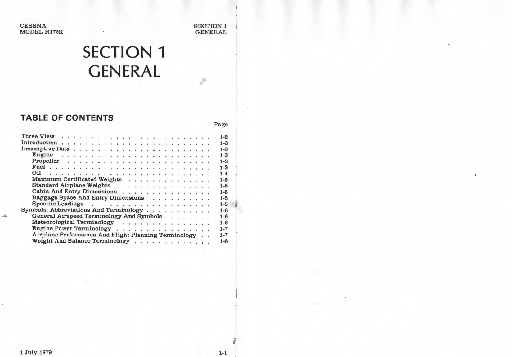
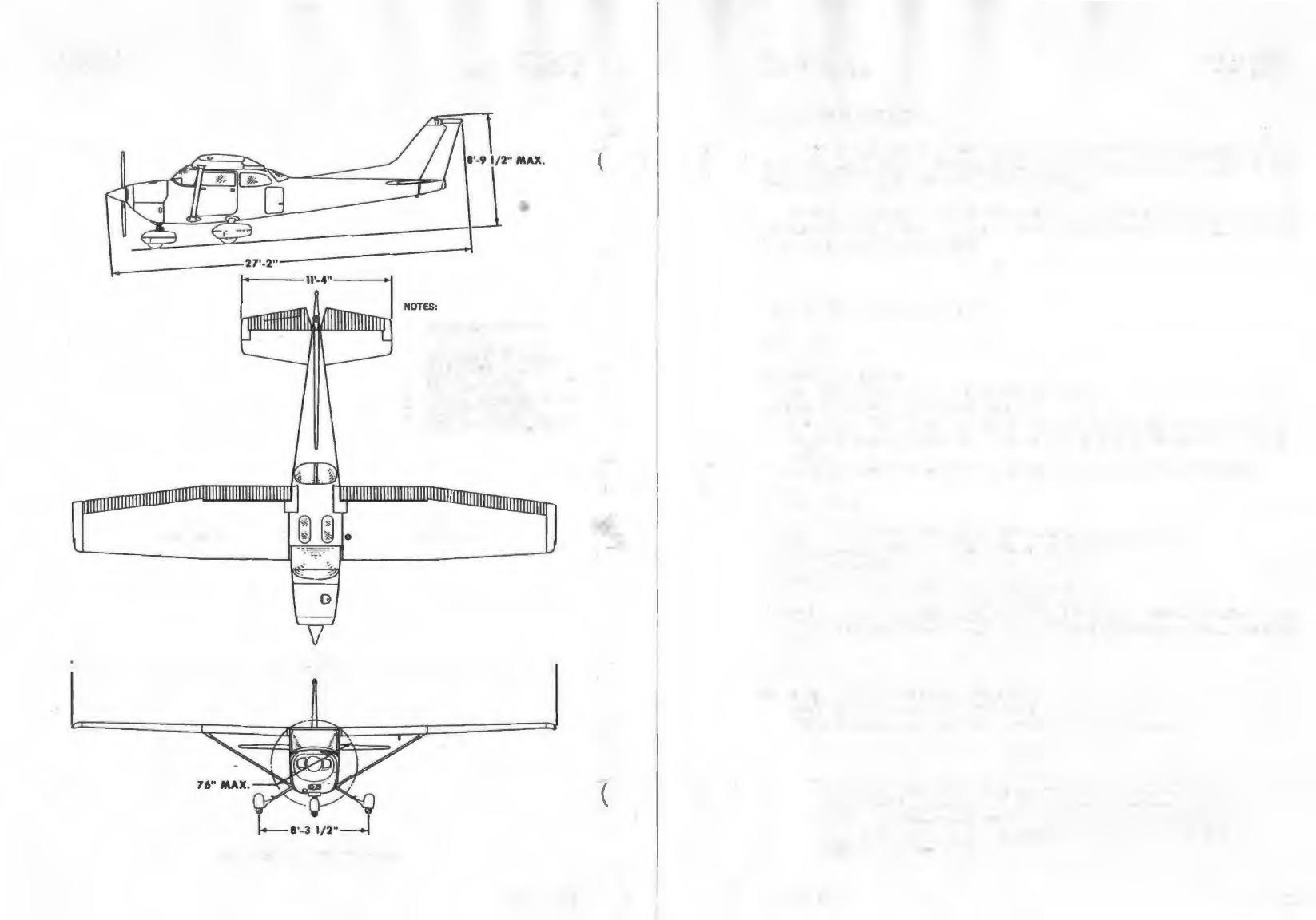
manuals.online logo
Brands
  1. Home
  2. •
  3. Brands
  4. •
  5. Cessna
  6. •
  7. Tools
  8. •
  9. Cessna R172K 1980 Owner's manual

Cessna R172K 1980 Owner's manual

t
(_
I /
PILOT'S
OPERATING
HANDBOOK
and
FAA
APPROVED
AIRPLANE
FLIGHT
MANUAL
l06
THIS
DOCUMENT
MUST
BE
CARRIED
IN
THE
AIRPLANE
AT
ALL
TIMES.
-
2'22
-:j
< 114 -
)I
CESSNA
AIRCRAFT
COMPANY I
I 1980
MODEL
R172K
Serial
No
: R1723306
Registration
No
.
VH-VPM
THIS
HANDBOOK
INCLUDES
THE
MATERIAL
REQUIRED
lO
BE
FURNISHED
TO
THE
PILOT
BY
CAR
PART
3
AND
CONSTITUTES
THE
FAA
APPROVED
AIRPLANE
FLIGHT
MANUAL.
f)
Memloe, of GAMA
COPYRICHT • 19
79
CESSNA
AIRCRAFT
COMPANY
WICHITA,
KANSAS
,
USA
1
JULY
1979
THIS
MANUAL
WAS
PROVIDED
FORTHEAIRPLANE
IDENTIFIED
ON
THE
TITLE PAGE
ON
If
-
't-
' ~1
?-,
SUBSEQUENT
REVISIONS
SUPPLIED BY
CESSNA
AIRCRAFT
COMPANY
MUST
BE PROPERLY
IN
-
SERTED
.
CESSNA
AIRCRAFT
COMPANY,
PAWNEE
DIVISION
I.
( I l
(
(
( j
( .I
j
CESSNA
MODELR172K
CONGRATULATIONS
CONGRATULATIONS
••••
Welcome
to
the ranks
of
Cess
na
owne
r
s!
Your
Cessna
has
been designed and
constructed to giveyou the mostin performance,economy,andcomfort.
It
is
ou
rdesirethat
you
will
f
ind
flying it, either
fo
r business
or
pleasure,apleasant and profitableexperience.
ThisPilot'sOperatingHand
book
has
been prepared
as
aguide
lo
helpyougetthemost
pleasure and
utility
from
your
airplane. It contains information about your
Cessna's
equip
ment, operating procedures, and performance; and suggestions
for
its servicingand
care. We urge you
to
read
it
from
cover
to
cover, and
to
refer to
it
frequently.
Our
in
terest in
your
flyi
ng
pleasure
has
not
ceased
with
your
pur
chase
of
a
Cessna.
World-wide, the
Cessna
Dealer Organization backed
by
the
Cessna
Customer Services
Department
stan
ds ready
to
serve you. The fo
llow
ing
servicesare offered
by
most
Cessna
Dealer
s:
• T
HE
CESSNA
WARRANTY,
wh
ich
pr
ovid
es
coverage
fo
rpartsand labor,isavailableat
Cessna
Dealers
worldwide
. Spec
ifi
c benefits and
pr
ovisions
of
warranty, plus
other
im
portant benefits for you,
are
contained in
yo
ur
Customer
Care
Program
book
,
supplied
with
your
airplane. Warranty service
is
available
to
youatauthorized
Cessna
Dealers
thr
ougho
ut
the
world
upon
pr
esentation
of
yourCustomerCareCard
which
es
tablishes
your
eligibility under
th
e warranty.
• FACTORY TRAIN
ED
PERSONNEL
to
provide
yo
u
with
courteous expert service.
• FACTORY
APPRO
VE
D
SERVICE
EQUIPMENT
to
provide you efficient and accurate
workmanship.
• A STOCK OF GENUINE
CESSN
A
SERV
I
CE
PARTS
on
hand when you need them.
•
THE
LATEST
AUTHORITATIVE INFORMATION FOR
SERV
ICING
CESSNA
AIR-
PLANES,
si
nce
Cess
na
D
ea
lers have all
of
the
Se
rviceManualsand
Parts
Catalogs,kept
c
urr
e
nt
by
Service Letters and Service News
lett
ers, published
by
Cessna
Aircraft
Company.
We urge all
Cessna
owne
rs
to
use
the
Cessna
Dealer Organization to the fulle
st.
A current
Cessna
Dealer Directory accompanies yo
ur
new airplane. The Directory is
revised frequently,and ac
urr
ent copycan beobtained
from
your
Cessna
Dealer.
Make
your
Directory one
of
ri°ur
cross-cou
ntr
y flight planning aids; a warm welcome awaits you at
every
Cessna
D
ea
er.
1
July
1979
PERFORMANCE-
SPECIFICATIONS
CESSNA
MODELR172K
PERFORMANCE SPECIFICATIONS
SPEED
:
Maximum
at
Sea.
Level
. . . . . . . . . . . . . . . 133
KNOTS
Cruise,
80%
Power
a.t 6000
Ft
. . . . . . . :, . . . • 130
KNOTS
CRUISE:
Recommended
lean
mixture
with
fuel
a.llowa.nce
for
engine
start,
taxi,
takeoff,
climb
and
45
minutes
reserve.
80%
Power
at
6000
Ft
. .
49
Gallons
Usable
Fuel
80%
Power
at
6000
Ft
. .
66
Gallons
Usable
Fuel
Maximum
Range
a.t 10,000
Ft
49 Ga.lions
Usable
Fuel
Maximum
Range
a.t 10,000
Ft
66
Gallons
Usable
Fuel
RATE
OF
CLIMB
AT
SEA
LEVEL
SERVICE
CEILING
. . . .
TAKEOFF
PERFORMANCE
:
Ground
Roll
. . . . . . . . .
Tota.I
Distance
Over
50-Ft
Obstacle
LANDING
PERFORMANCE:
Ground
Roll
. . . . . . . . . .
Total
Distance
Over
50-Ft
Obstacle
ST
ALL
SPEED
(CAS):
Flaps
Up,
Power
Off
Flaps
Down,
Power
Off
MAXIMUM
WEIGHT:
Ramp
.......
.
Takeoff
or
Landing
. .
STANDARD
EMPTY
WEIGHT:
HawkXP
......
.
HawkXPil
.....
.
MAXIMUM
USEFUL
LOAD:
HawkXP
...
. . .
HawkXPil
.....
.
BAGGAGE
ALLOWANCE
WING
LOADING
:
Pounds/Sq
Ft
POWER
LOADING:
Pounds/HP
FUEL
CAPACITY
:
Total
Standard
Tanks
Long
Range
Ta.n.lni
OIL
CAPACITY
ENGINE:
Teledyne
Continental,
Fuel
Injection
195
BHP
at
2600
RPM
PROPELLER:
Constant
Speed,
Diameter
. . .
ii
.
Range
Time
.
Range
Time
.
Range
Time
.
Range
Time
440NM
3.4
HRS
635NM
4.9
HRS
575NM
6.1HRS
815NM
8.
7HRS
870FPM
17,000
FT
SOOFT
1380FT
~OFT
1270
FT
53
KNOTS
46KNOTS
2558
LBS
2550
LBS
1538LBS
1565LBS
1020LBS
993LBS
200LBS
14.7
13.1
52
GAL.
68
GAL.
. 1
9QTS
iO'-360-KB
761N.
1
Juiy
1979
(
(
( I
CESSNA
MODELR172K
COVERAGE
/
REVISIONS/
LOG
OF
EFFECTIVE
PAGES
COVERAGE
The Pilot's
Operating
Handbook
in
the
airplane at
the
l
ime
of
delivery from Cessna Aircraft
Company
co
ntai~s i
nfo
rmationapplicable
to
t
he
1980
Mode
l
R172K
airplane designat
ed
by
the
serial
number
and
reg1
str
at1on
number
sh
own
on
the
Title Page
of
this h
andbook.
REVISIONS
. Changes an
d/or
additions
to
this
handbook
will
be
covered
by revisions
published
by Cessna
Aircraft Company. Th
ese
revisions
are
distributed
to
all Cessna Dealers
and
to
owners
or
u.
s.
Registered aircraft
according
to
FAA
rec
ords
at
the
time of revision
iss
uance.
Revisions
sho
uld be
examined
immediacely
upon
r
eceip
1
and
in
cor
po
raced in
th
is
handbook
.
NOTE
It is
th
e responsibility
of
the owner
lo
maint
ai
n this handbookina current
status
when
it
is being used
for
operational purposes.
Owners
shou
ld
contact
t
heir
Cessna
Dealer
whenever
the
revision status
of
lheir
handb
ook
is
in
question.
A revision
bar
will
ex
t
end
the
full length
of
new
or
revi
se
d text
and/or
illustrations
added
on
new
or
presenlly existing pages. This
bar
will
be
located
adjacent
to
the
applicable revised area
on
th
e
outer
margin
of
the
page.
All r
ev
is
ed
pages will carry
the
revisi
on
number
and
dace
on
the
applicable
page.
The following Log
of
EffectivePagesprovidesthe
da
t
es
of issuefor original
and
revi
se
d pages,
and
a listing
of
a
ll
pages
in
the
handbook
. Pages affected by
the
curren
t revision
are
indi
ca
ted
by an
asterisk (•)
preceding
th
e pages listed.
LOG
OF
EFFECTIVE PAGES
Dates
of
issue for original
and
revised
pag
es
are
:
Original
...............
1 July 1979
Revision 1
......
15
Novembe
r 1979
h~
~re
Pa~
Date
TIiie
.....................
1 July 1979
Assignmen1 Re
co
rd
......
. 1 July 1979
i
thru
ii
..................
1 July1979
•iii
................
15
November
1979
iv
........................
1 July 1979
1-1 thru 1-9
..............
1
Ju
ly 1979
1-10
Bl
ank
....
.
......
.
....
1 July
19
79
2-1
......................
1 July 1979
2-2 Blank
.................
1 July 1979
2-3 thru 2-13
.............
1 July
19
79
2-14 Blank
................
1 July 1979
3-1 thru 3-9
..
.
...........
1 July 1979
3-10
Blan
k-:
...............
1 July 1979
3-11
thr
t.i
3-
18
....
..
......
1 July 1979
4-1
thru 4-
11
.............
1
Ju
ly 1979
4-12 Blank
..............
..
1 July 1979
4-13
thru
4-25
.........
..
. 1 July 1979
4-26 Blank
................
1 July 1979
5-1
......................
1 July 1979
5-2 Blank
.........
........
1 July1979
1
July
1979
5-3 t
hru
5-27
.............
1 July 1979
5-28 Blank
................
1 July 1979
6-1
..............
..
......
1 July 1979
6-2 Bl
ank
..........
..
..
...
1 July 1979
6-3
thru
6-23
.....
.
...
....
1 July 1979
6-24
Bl
ank
................
1 July 1979
7-1
thru
7-43
..........
..
. 1 July 1979
7-44 Blank
..........
...
...
1 July 1979
8-1
......................
1 July 1979
8-2 Blank
.................
1 July 1979
8-3
thru
8-17
.............
1 July 1979
8-18 Blank
....
............
1 July 1979
*9-1
...
..
..........
15
November
1979
9-2
......................
1 July 1979
NOTE
Refer
to
Section 9 Table
of
Con
te
nts
for
supple
m
en
ts applicable
10
optional
sys-
tems.
Revision
1 -
15
November
1979
D1173-l-lJPH
iii
T
ABL
E
OF
CON
TENT
S
CESSNA
MODEL
R172K
TABLE
OF
CONTENTS
SECTION
GENERAL...
..
..
..
.....
. . .
..
. .
....
. .
..
1
LIMITATIONS
..
...
. .
...
.
....
...
....
..
. 2
EMERGENCY PROCEDURES
..
...
. . . . .
..
3 .
,-
NORMAL
PROCEDURES . . .
.....
.
......
4
PERFORMANCE. . .
..
.
...
.....
..
. .
.....
5
WEIGHT
& BALANCE/
EQUIPMENT
LIST
..
. .
....
. . . .
...
..
6
AIRPLANE & SYSTEMS
DESCRIPTIONS
..
.......
..
........
7
AIRPLANE
HANDLING
,
SERVICE &
MAINTENANCE
...
...
..
8
SUPPLEMENTS
(Optional
Systems Desc
ription
&
Operating
Procedures) . .
...
..
.
..
9
(
CESSNA
MODELR172K
SECTION
1
GENERAL
TABLE OF
CONTENTS
Three
View
Introduction
Descriptive
Data
Engin
e
Propeller
Fuel
..
.
Oil
Maximum
Certificated
Weights
Sta.nda.rd
Airplane
Weights
. .
Ca.bin
And
Entry
Dimensions
.
Baggage
Space
And
Entry
Dimensions
Specific
Loa.dings
. . . . . . . . . .
Symbols
,
Abbreviations
And
Terminology
.
General
Airspeed
Terminology
And
Symbols
Meteorological
Terminology
. . . . . . . .
Engine
Power
Terminology
. . . . . . . . .
SECTION
1
GENERAL
Airplane
Performance
And
Flight
Planning
Terminology
Page
1-2
1-3
1-3
1-3
1-3
1-3
1-4
1-5
1-5
1-5
1-5
1-5
1-6
1-6
1-6
1-7
1-7
1-8
Weight
And
Ba.lance
Terminology
...
. . .
....
.
1
July
1979
1-1
'


*
  0

 
  

   
 
  

  
   
     
    
   
*
 

 
 
(
( (
(




INTRODUCTION



       


DESCRIPTIVE DATA

  
  
 
 
      

     

 
  
 
 
 
       
° 



   

   
  
   


 
(
3ECTION
1
lENERAL
"uel
Capacity:
Standard
Tanks:
Total
Ca.pa.city:
52
ga.llons
.
Total
Ca.pa.city Ea.ch
Tanlc
26
ga.llons.
Total
Usable:
49
gallons.
Long
Range
Tanks:
Total
Ca.pa.city: 68 ga.llons.
Total
Ca.pa.city Ea.ch
Tank:
34
gallons
.
Total
Usable:
66
ga.llons
.
NOTE
CESSNA
MODELR172K
To
ensure
maximum
fuel
capacity
when
refueling
and
minimize
cross-feeding
when
parked
on
a
sloping
surface
,
place
the
fuel
selector
valve
in
either
LEFT
or
RIGHT
position.
)IL
)il
Grade
(Specification):
MIL-L-6082
Aviation
Grade
Straight
Mineral
Oil
:
Use
to
replenish
supply
during
first
25
hours
and
at
the
first
25-hour
oil
change
.
Continue
to
use
until
a
total
of
50
hours
has
accumulated
or
oil
1
cousumption
has
stabilized.
\
NOTE
The
airplane
was
delivered
from
the
factory
with
a.
corrosion
preventive
aircraft
engine
oil
.
This
oil
should
be
drained
after
the
first
25
hours
of
operation.
Continental
Motors
Specification
MHS-24
(and
a.11
revisions
thereto)
,
Ashless
Dispersant
Oil:
Thia
oil
must
be
u
■
ed
after
first
50
hours
or
oil
consumption
has
stabilized.
tecommended
Viscosity
for
Temperature
Range:
SAE
20W-50
or
SAE
50
above
40°F
(4°C).
SAE
20W-50
or
SAE
30
below
40°F
(4°C).
NOTE
Multi-viscosity
oil
with
a
range
of
SAE
20W-
50
is
recom-
mended
for
improved
starting
in
cold
weather.
)il
Capacity:
-4
Sump:
8
Quarts.
Total
: 9
Quarts
.
1
July
1979
(
(
(
CESSNA
MODELR172K
SECTION
1
GENERAL
MAXIMUM
CERTIFICATED
WEIGHTS
Ramp,
Norma.I
Category:
2558
lbs
.
Utility
Category:
2208
lbs.
Takeoff,
Normal
Category:
2550
lbs
.
Utility
Category
: 2200
lbs
.
Landing,
Normal
Category:
2550
lbs
.
Utility
Category
: 2200
lbs.
Weight
in
Baggage
Compartment,
Normal
Cat
egory:
B
aggage
Area. 1
or
Passeng
er
on
Child
's
Seat-
(Bagg
age,
Stati
on
82
to
108, 200
lbs.
maximum;
Passen
ger
on
Child
's
Seat
, 120
lbs
. ma.xi-
mum)
.
See
note
below
.
Baggage
Area. 2 -
Station
108
to
142:
50
lbs.
Se
e
note
below
.
NOTE
The
maximum
com
bined
weight
ca.pa.city
for
bag
gage
areas
1
and
2
is
200
lb
s.
Weight
in
Baggage
Compartment
,
Utility
Category:
In
this
category,
the
baggage
compartment
and
rear
seat
must
not
be
occupied.
STANDARD
AIRPLANE
WEIGHTS
Standard
Em
pty
Weight,
Ha.wk
XP
: 1538
lbs
.
Maximum
Useful
Load
:
Ha.wk
XP:
Ha.wk
XP
Il
:
Hawk
XP
II
: 1565
lbs.
Norma.I
Category
1020
lbs
.
993
lb
s.
CABIN
AND
ENTRY
DIMENSIONS
Utility
Category
670
lbs.
643
lbs.
Detailed
dimensions
of
the
ca.bin
interior
and
entry
door
openings
a.re
illustrated
in
Section
6.
BAGGAGE
SPACE
AND
ENTRY
DIMENSIONS
Dimensions
of
the
baggage
area.
and
baggag
e
do
or
opening
are
illustrated
in
detail
in
Se
ction
6.
SPECIFIC
LOADINGS
Wing
Loading:
14.7
lbs./sq
.
ft
.
Power
Loading:
13.1
lbs./hp
.
1
July
1979 1
-5
SECTION
1
GENERAL
CESSNA
MODELRl72K
SYMBOLS,
ABBREVIATIONS
AND
TERMINOLOGY
GENERAL
AIRSPEED
TERMINOLOGY
AND
SYMBOLS
KCAS
KIAS
KTAS
Knots
Calibrated
Airspeed
is
indicated
airspeed
corrected
f
or
position
and
instrument
error
and
expressed
in
knots
.
Knots
calibrated
airspeed
is
equal
to
KT
AS
in
standard
atmosphere
at
sea
level
.
Knots
Indicated
Airspeed
is
the
speed
shown
on
the
airs
p
eed
indicator
and
expresse
d
in
knots.
Knots
True
Airspeed
is
the
airspeed
expressed
in
knots
relative
to
undisturbed
air
which
is
KCAS
corrected
for
altitude
and
temperature
.
Manuevering
Speed
is
the
maximum
speed
at
whi
ch
you
may
us
e
abrupt
control
travel.
Maximum
Flap
Extended
Speed
is
the
highest
speed
permissible
with
wing
flaps
in
a
prescribed
extended
(
position
. (
Maximum
Structural
Cru.i.
sing
Speed
is
the
speed
that
should
not
be
exceeded
except
in
smooth
air,
then
only
with
caution.
Never
Exceed
Speed
is
the
speed
limit
that
may
not
be
exceeded
at
any
time.
Stalling
Speed
or
the
minimum
steady
night
speed
at
which
the
airplane
is
controllable.
Stalling
Speed
or
the
minimum
steady
night
speed
at
which
the
airplane
is
controllable
in
the
landin
g
configu
-
ration
at
the
most
forward
center
of
gravity.
Best
Angle
-
of
-
Climb
Speed
is
the
speed
which
results
in
the
greatest
gain
of
altitude
in
a
given
horizontal
distance.
Best
Rate-of-Climb
Speed
is
the
speed
which
results
in
the
greatest
gain
in
altitude
in
a
given
time.
(
METEOROLOGICAL
TERMINOLOGY
OAT
Outside
Air
Temperature
is
the
free
air
static
temperature.
1-6 1
July
1979
CESSNA
MODELR172K
Standard
Tempera-
ture
Pressure
Altitude
SECTION
1
GENERAL
It
is
expressed
in
either
degrees
Celsius
or
degrees
Fah-
renheit
.
Standard
Temperature
is
15°C
at
sea
level
pressure
altitude
and
decreases
by
2°C
for
each
1000
feet
of
altitude
.
Pressure
Altitude
is
the
altitude
read
from
an
altimeter
when
the
altimeter's
barometric
scale
has
been
set
to2.9.92
inches
of
mercury
(1013
mb)
.
ENGINE
POWER
TERMINOLOGY
BHP
RPM
MP
Brake
Horsepower
is
the
power
developed
by
the
engine.
Revolutions
Per
Minute
is
engine
speed.
Manifold
Pressure
is
a
pressure
measured
in
the
engine
's
induction
system
and
is
expressed
in
inches
of
mercury
(Hg).
AIRPLANE
PERFORMANCE
AND
FLIGHT
PLANNING
TERMINOLOGY
Demon-
strated
Crosswind
Velocity
Usable
Fuel
Unusable
Fuel
GPH
NMPG
g
1
July
1979
Demonstrated
Crosswind
Velocity
is
the
velocity
of
the
crosswind
component
for
which
adequate
control
of
the
airplane
during
takeoff
and
landing
wa.s
actually
demon-
strated
during
certification
tests
.
The
value
shown
is
not
considered
to
be
limiting.
Usable
Fuel
is
the
fuel
available
for
flight
planning.
Unusable
Fuel
is
the
quantity
of
fuel
that
can
not
be
safely
used
in
flight
.
Gallons
Per
Hour
is
the
amount
of
fuel
(in
gallons)
consumed
per
hour
.
Nautical
Miles
Per
Gallon
is
the
distance
(in
nautical
miles)
which
can
be
expected
per
gallon
of
fuel
consumed
at
a
specific
engine
power
setting
a.nd/
or
flight
configura-
tion.
g
is
acceleration
due
to
gravity.
1-7
SECTION
1
GENERAL
CESSNA
MODELR172K
WEIGHT
AND
BALANCE
TERMINOLOGY
Reference
Datum
Station
Arm
Moment
Center
of
Gravity
(C.G.)
C.G.
Arm
C.G.
Limits
Standard
Empty
Weight
Basic
Empty
Weight
Useful
Load
Maximum
Ramp
Weight
MMCimum
Takeoff
Weight
1-8
Reference
Datum
is
an
imaginary
vertical
plane
from
which
all
horizontal
distances
a.re
measured
for
balance
purposes.
Station
is
a
location
along
the
airplane
fuselage
giV'en
in
terms
of
the
distance
from
the
reference
datum.
Arm
is
the
horizontal
distance
from
the
reference
datum
to
the
center
of
gravity
(C.G.)
of
an
item.
Moment
is
the
product
of
the
weight
of
an
item
multiplied
by
its
arm.
(Moment
divided
by
the
constant
1000
is
used
in
this
handbook
to
simplify
balance
calculations
by
reduc-
ing
the
number
of
digits
.)
Center
of
Gravity
is
the
point
at
which
an
airplane,
or
equipment,
would
balance
if
suspended.
Its
distance
from
the
reference
datum
is
found
by
dividing
the
total
moment
by
the
total
weight
of
the
airplane.
Center
of
Gravity
Arm
is
the
arm
obtained
by
adding
the
airplane's
individual
moments
and
dividing
the
sum
by
the
total
weight.
Center
of
Gravity
Limits
are
the
extreme
center
of
gravity
locations
within
which
the
airplane
must
be
operated
at
a
given
weight.
Standard
Empty
Weight
is
the
weight
of
a.
standard
airplane,
including
unusable
fuel,
full
opera.ting
fluids
and
full
engine
oil.
Basic
Empty
Weight
is
the
standard
empty
weight
plus
the
weight
of
optional
equipment.
Useful
Load
is
the
difference
between
ramp
weight
and
the
basic
empty
weight.
Ma.xi.mum
Ramp
Weight
is
the
maximum
weight
approved
for
ground
maneuver
.
(It
includes
the
weight
of
start,
ta.xi
and
runup
fuel.)
(
Ma.xi.mum
Takeoff
Weight
is
the
maximum
weight
ap-
proved
for
the
start
of
the
takeoff
run.
1
July
1979
(
(
(
CESSNA
MODELR172K
Maximum
Landing
Weight
Ta.re
1
July
1979
SECTION
1
GENERAL
M.
aximum
Landing
Weight
is
the
maximum
weight
approved
for
the
landing
touchdown.
Tare
is
the
weight
of
chocks,
blocks
,
stands,
etc
.
used
when
weighing
an
airplane,
and
is
included
in
the
scale
readings.
Ta.re
is
deducted
from
the
sea.le
reading
to
obtain
the
actual
(net)
airplane
weight.
1-9/(1-10
blank)
I
\
,
/
CESSNA
MODELR172K
SECTION 2
LIMITATIONS
TABLE OF
CONTENTS
Introduction
. . . . . . . .
Airspeed
Limitations
Airspeed
Indicator
Markings
Power
Plant
Limitations
Power
Plant
Instrument
Markings
Weight
Limits
. . . . .
Normal
Category
. .
Utility
Category
Center
Of
Gravity
Limits
Normal
Category
Utility
Category
Maneuver
Limits
Normal
Category
Utility
Category
Flight
Load
Factor
Limits
Normal
Category
. . .
Utility
Category
Kinds
Of
Operation
Limits
Fuel
Limitations
. .
Other
Limitations
Flap
Limitations
Placards
..
. . .
1
July
1979
SECTION
2
LIMITATIONS
Page
2-3
2-4
2-5
2-5
2-6
2-6
2-6
2-7
2-7
2-7
2-7
2-7
2-7
2-8
2-8
2-8
2-8
2-9
2-9
2-9
2-9
2-10
2-
1/
(2-2
blank)
(
CESSNA
MODELR172K
SECTION
2
LIMITATIONS
INTRODUCTION
Section
2
includes
operating
limitations,
instrument
markings
,
and
ba.sic
placards
necessary
for
the
safe
operation
of
the
airplane,
its
engine
,
standard
systems
and
standard
equipment.
The
limitations
included
in
this
section
and
in
Section
9
have
b
een
approved
by
the
Federal
Av
iation
Administration
.
Observance
of
these
operating
limitations
is
re
quired
by
Federal
Aviation
Regulations.
NOTE
Refer
to
Section
9
of
this
Pilot's
Operating
Handbook
for
a.mended
operating
limitations
,
operating
procedures
,
performance
data
and
other
necessary
information
for
airplanes
equipped
with
specific
options
.
NOTE
The
airspeeds
listed
in
the
Airspeed
Limitations
chart
(figure
2-1)
and
the
Airspeed
Indicator
Markings
cha.rt
(figure
2-
2)
are
b
ased
on
Airspee
d
Calibration
data
shown
in
Section
5
with
the
normal
static
source.
If
the
alternate
static
source
is
being
used
,
ample
margins
should
be
observed
to
allow
for
the
airspeed
calibration
variations
between
the
normal
and
alternate
static
sources
as
shown
in
Section
5.
Your
Cessna
is
certificated
under
FAA
Type
Certificate
No. 3A17 as
Cessna
Model
No
.
R172K
.
1
July
1979 2
-3
SECTION
2
LIMITATIONS
AIRSPEED
LIMITATIONS
CESSNA
MODEL
R172K
Airspeed
limitations
and
their
operational
significance
are
shown
in
figure
2-1.
Maneuvering
speeds
shown
apply
to
normal
category
opera-
tions.
The
utility
category
maneuvering
speed
is
105
KIAS
at
2200
pounds
.
SPEED
KCAS
KIAS REMARKS
VNE Never Exceed Speed 161 163 Do
not
exceed this speed in
any operation.
VNO
Maximum Structural 127 129 Do
not
exceed this speed
Cruising Speed except
in
smooth air,
and
then
only with caution.
VA Maneuvering Speed:
2550
Pounds
103
104 Do
not
make full
or
abrupt
2150
Pounds
94 95
control movementsabove
17
50 Pounds
85 85
thisspeed.
VFE Maximum Flap Extended
Speed:
10°
Flaps
108
110 Do
not
exceed this speed
100
-
400
Flaps 84
85
with flaps down.
Maximum Window Open 161
163
Do
not
exceed this speed with
Speed windows open.
Figure
2-1.
Airspeed
Limitations
-4
1
July
1979
(
( (
CESSNA
MODELR172K
AIRSPEED
INDICATOR
MARKINGS
SECTION
2
LIMITATIONS
Airspeed
indicator
markings
and
their
color
code
significance
are
shown
in
figure
2-2.
MARKING KIAS VALUE SIGNIFICANCE
OR RANGE
White Arc 38 -
85
Full Flap Operating Range. Lower
limit is maximum weight
Vs
in
landing configuration.
Uppe}>
limit
is
maximum speed permissible with
flaps extended.
Green Arc
48
- 1
29
Normal Operating Range. Lower limit
is
maximum weight
Vs
at
most
forward
C.G
. with flaps retracted. Upper limit
is
maximum structural cruising speed.
Yellow Arc
129
- 1
63
Operations must be conducted with
caution
and
only in smooth air.
R
ed
Line 1
63
Maximum speed for all operations.
Figure
2-2.
Airspeed
Indicator
Markings
POWER PLANT
LIMITATIONS
Engine
Manufacturer:
Teledyne
Continental.
Engine
Model
Number:
10-360-KB
.
Engine
Operating
Limits
for
Takeoff
and
Continuous
Operations:
Maximum
Power:
195
BHP
rating.
Maximum
Engine
Sp
eed:
2600
RPM.
Ma.xi.mum
Cylinder
Head
Temperature
:
460°F
(238°C).
Maximum
Oil
Temperature:
240°F
(116°
C)
.
Oil
Pressure,
Minimum:
10
psi.
Ma.ximum:
100
psi.
Fuel
Pressure,
Minimum:
3
psi.
Ma.xi.mum: 17
psi
(17
gal/hr).
Propeller
Manufacturer:
McCauley
Accessory
Division.
Propeller
Model
Number:
2A34C203/90DCA-14
.
Propeller
Dia.meter,
Maximum:
76
inches.
Minimum:
74.5
inches
.
Propeller
Blade
Angle
at
30
Inch
Station
,
Low
: 1
2.0
°.
High:
25.1°.
1
July
1979
SECTION
2
LIMITATIONS
GESSNA
MODEL
R172K
POWER PLANT
INSTRUMENT
MARKINGS
Power
plant
instrument
markings
a.nd
their
color
code
significance
(
are
shown
in
figure
2-3.
RED LINE GREEN ARC
INSTRUMENT
MINIMUM
NORMAL
LIMIT
OPERATING
Tachometer ---2200 -
2600
RPM
Manifold
Pressure
-- -
15
-
25
in.
Hg
Oil Temperature ---
100°
-
240°F
Cylinder Head -- - 2000 -
4600
F
Temperature
Fuel Fl
ow
(Pressure) (3 psi) 4.5 -
11
.5 gal/hr
Oil
Pressure
10
ps
i 30 -
60
psi
Fuel
Quantity
E - --
(Standard (1.5 Gal. Unusable
Tanks)
Each
Tank)
Fuel Quantity E ---
(Long
Range
(1.0 Gal. Unusable
Tanks)
Each
Tank)
Suction - --4.5 - 6.4
in
. Hg.
Figure
2-3.
Power
Plant
Instrument
Markings
WEIGHT LIMITS
NORMAL
CA
TEGORY
Maximum
Ra.mp
Weight:
2558
lbs
.
Maximum
Takeoff
Weight: 2550
lbs.
Maximum
Landing
Weight:
2550
lbs
.
RED
LINE
MAXIMUM
LIMIT
2600
RPM
-- -
2400F
460°F
17
gal/hr
(17 psi) (
100
psi
---
-- -
---
1
July
1979
CESSNA
MODELR172K
SECTION
2
LIMITATIONS
Maximum
Weight
in
Baggage
Compartment:
Baggage
Area
1
or
Passenger
on
Child
's
Seat
-
(Baggage
,
Station
82
to
108, 200
lbs.
mu:imum;
Passenger
on
Child's
Sea.t 120
lbs
.
max-
imum).
See
note
below.
Baggage
Area. 2 -
Station
108
to
142: 50
lbs.
See
note
below
.
NOTE
The
maximum
combined
weight
ca.pa.city
for
baggage
areas
1
and
2
is
200
lbs
.
UTILITY CATEGORY
Maximum
Ra.mp
Weight:
2208
lbs
.
Maximum
Takeoff
Weight:
2200
lbs.
Maximum
Landing
Weight:
2200
lbs.
Maximum
Weight
in
Baggage
Compartment:
In
the
utility
category
,
the
b
aggage
compartment
and
rea.r sea.t
must
not
be
occupied
.
CENTER OF
GRAVITY
LIMITS
NORMAL
CATEGORY
Center
of
Gravity
Range
:
Forward:
35.0
inches
a.ft
of
datum
at
1950lbs.
or
less,
with
straight
line
variation
to
41.0
inches
aft
of
datum
at
2550
lbs
.
Aft: 47.3
inches
a.ft
of
datum
a.t
a.11
weights.
Reference
Datum:
Lower
portion
of
front
face
of
firewa.11.
UTILITY
CA
TEGORY
Center
of
Gravity
Range:
Forward:
35.0
inches
aft
of
datum
a.t 1950
lbs
.
or
less,
with
straight
line
variation
to
37.5
inches
a.ft
of
datum
at
2200
lbs
.
Aft:
40.5
inches
a.ft
of
datum
at
a.ll
weights
.
Reference
Datum:
Lower
portion
of
front
fa.ce
of
firewa.11.
MANEUVER
LIMITS
N
ORMA
L CATEGORY
This
airplane
is
certificated
in
both
the
normal
and
utility
category
.
The
normal
category
is
applicable
to
aircraft
intended
for
non-aerobatic
operations.
These
include
any
maneuvers
incidenta.l
to
normal
flying,
stalls
(except
whip
stalls),
lazy
eights,
cha.ndelles
,
and
turns
in
which
the
angle
of
bank
is
not
more
than
60°.
Aerobatic
maneuvers,
including
spins,
a.re
not
approved.
1
July
1979 2-7
r
SECTION2
LIMITATIONS
CESSNA
MODELR172K
UTILITY CATEGORY
This
a.irplane
is
not
designed
for
purely
aeroba.tic
flight.
However,
in
the
acquisition
of
va.rious
certificates
such
as
commercia.l
pilot
and
flight
instructor,
oerta.in
maneuvers
a.re
required
by
the
FAA.
All
of
these
maneuvers
a.re
permitted
in
this
airplane
when
operated
in
the
utility
category
.
In
the
utility
category
,
the
baggage
compartment
and
rear
seat
must
not
be
occupied.
No
aerobatic
maneuvers
a.re
approved
except
those
listed
below:
MANEUVER
Chandelles
.
Lazy
Eights
.
Steep
Turns
- .
RECOMMENDED
ENTRY
SPEED*
. .
...
110
knots
.
..
..
110
knots
.
....
104
knots
v
Spins
..
..
.
Slow
Deceleration
.
Slow
Deceleration
Sta.lls
(Except
Whip
Stalls)
•
Abrupt
use
of
the
controls
is
prohibited
above
104
knots.
Aerobatics
tha.t
ma.y
impose
high
loads
should
not
be
attempted.
The
important
thing
to
bea.r
in
mind
in
flight
maneuvers
is
tha.t
the
airplane
is
clean
in
aerodynamic
design
and
will
build
up
speed
quickly
with
the
nose
down.
Proper
speed
control
is
a.n
essential
requirement
for
execution
of
a.ny
ma.neuver,
and
ca.re
should
always
be
exercised
to
avoid
excessive
speed
which
in
turn
ca.n
impose
excessive
loads
.
In
the
execution
of
a.ll
maneuvers,
avoid
abrupt
u.
se
of
controls.
Intentional
spins
with
flaps
extended
are
prohibited.
FLIGHT LOAD FACTOR LIMITS
NORMAL
CATEGORY
Flight
Load
Fa.ctors
(Max
.
imum
Takeoff
Weight
-2550
lbs
.):
*Flaps
Up
..................
+3.Sg, -1.52g
*Flaps
Down
. . . . . . . . . . . . . . . . . +3.0g
*The
design
load
factors
are
150%
of
the
above,
and
in
all
cases,
the
structure
meets
or
exceeds
design
loads.
UTILITY CATEGORY (
Flight
Loa.d
Factors
(Ma.xi.mum
Takeoff
Weight
-2200
lbs
.):
*Flaps
Up
.
+4.
4g
, -1.76g
*Flaps
Down
. . . . . . . . . . . . . . . . ._+3.0g
2-8 1
July
1979
{
(
(
CESSNA
MODELR172K
SECTION
2
LIMITATIONS
*The
design
loa.d
factors
a.re
150
%
of
the
above,
and
in
all
cases,
the
structure
meets
or
exceeds
design
loads.
KINDS
OF
OPERATION
LIMITS
The
airplane
is
equipped
for
day
VFR
and
may
be
equipped
for
night
VFR
and/
or
IFR
operations.
FAR
Part
91
establishes
the
minimum
required
instrumentation
a.nd
equipment
for
these
operations.
The
refer-
ence
to
types
of
flight
operations
on
the
opera.ting
limitations
pla
card
reflects
equipment
installed
at
the
time
of
Airworthiness
Certificate
issuance.
Flight
into
known
icing
conditions
is
prohibited
.
FUEL LIMITATIONS
2
Standard
Tanks:
26
U.S.
ga.llons
each.
Total
Fuel:
52
U.S.
ga.llons.
Usable
Fuel
(all
night
conditions):
49
U.S.
gallons.
Unusable
Fuel:
3
U.S.
gallons
.
2
Long
Range
Tanks:
34
U.S.
gallons
each.
Total
Fuel:
68
U.S.
gallons.
Usable
Fuel
(all
flight
conditions):
66
U.S.
gallons
.
Unusable
Fuel:
2 U.S.
ga.llons.
NOTE
To
ensure
maximum
fuel
ca.pa.city
when
refueling
and
minimize
cross-feeding
when
parked
on
a
sloping
surface,
place
the
fuel
selector
valve
in
either
LEFT
or
RIGHT
position
.
Fuel
rema.ining
in
the
tank
after
the
fuel
quantity
indicator
reads
empty
(red
line)
cannot
be
safely
used
in
night.
Approved
Fuel
Grades
(and
Colors):
lOOLL
Grade
Aviation
Fuel
(Blue).
100
(Formerly
100/130)
Grade
Aviation
Fuel
(Green).
OTHER LIMITATIONS
FLAP LIMITATIONS
Approved
Takeoff
Range:
0°
to
15
°.
Approved
Landing
Range
: 0°
to
40
°.
1
July
1979 2-9
SECTION
2
LIMITATIONS
PLACARDS
CESSNA
MODEL
R172K
The
following
information
must
be
displayed
in
the
form
of
composite
(
or
individual
placards.
1.
In
full
view
of
the
pilot
:
(The
"DAY
-
NIGHT-VFR-IFR!
'
entry,
shown
on
the
example
below,
will
va.ry
as
the
airplane
is
equipped.)
The
markings
and
placards
installed
in
this
airplane
contain
operating
limitations
which
must
be
complied
with
when
operat
-
ing
this
airplane
in
the
Normal
Category.
Other
operating
limita-
tions
which
must
be
complied
with
when
operating
this
airplane
in
this
category
or
in
the
Utility
Category
are
contained
in
the
Pilot
's
Operating
Handbook
and
FAA
Approved
Airplane
Flight
Manual.
Normal
Category
-
No
acrobatic
maneuvers,
including
spins,
approved.
Utility
Category
-
No
acrobatic
maneuvers
approved
,
Spin
Recovery
except
those
listed
in
the
Pilot's
Opera.ting
Handbook.
Baggage
compartment
and
rear
seat
must
not
be
occupied
.
-
Opposite
rudder
-
forward
elevator
-
neutralize
controls.
Flight
into
known
icing
conditions
prohibited.
This
airplane
is
certified
for
the
following
flight
operations
as
of
date
of
original
airworthiness
certificate:
DAY-NIGHT-VFR-IFR
2.
Near
wing
fi.ap
switch:
AVOID
SLIPS
WITH
FLAPS
EXTENDED
2-10 1
July
1979
{
(
(
CESSNA
MODELR172K
SECTION
2
LIMITATIONS
3.
On
the
fuel
selector
plate
(standard
tanks):
BOTH
-49
GAL.
LEFT
-
24.5
GAL.
RIGHT
-24.5
GAL
.
WHEN
SWITCHING
FROM
DRY
TANK
TURN
PUMP
ON
"HI
"
MOMENTARILY
On
the
fuel
selector
plate
(long
range
tanks):
BOTH
-66
GAL.
LEFT
-33
GAL
.
RIGHT
-33
GAL.
WHEN
SWITCHING
FROM
DRY
TANK
TURN
PUMP
ON
"HI"
MOMENTARILY
4.
Near
fuel
tank
filler
cap
(standard
tanks):
5.
FUEL
100LL/100
MIN.
GRADE
AVIATION
GASOLINE
CAP.
26
U.S.
GAL
.
Near
fuel
tank
filler
cap
(long
range
tanks)
:
FUEL
100LL/100
MIN.
GRADE
AVIATION
GASOLINE
CAP
. 34.0
U.S
.
GAL
.
CAP.
26.0
U.S
.
GAL.
TO
BOTTOM
OF
FILLER
COLLAR
On
control
lock:
CONTROL
LOCK
REMOVE
BEFORE
STARTING
ENGINE
.
1
July
1979 2-11
SECTION
2
LIMITATIONS
CESSNA
MODEL
R172K
6.
In
baggage
compartment:
200
POUNDS
MAXIMUM
BAGGAGE
OR
120
LBS
AUX
SEAT
PASSENGER
FORWARD
OF
BAGGAGE
DOOR
LATCH
50
POUNDS
MAXIMUM
BAGGAGE
A.FT
OF
BAGGAGE
DOOR
LATCH
MAXIMUM
200
POUNDS
COMBINED
FOR
ADDITIONAL
LOADING
INSTRU
CTIONS
SEE
WEIGHT
AND
BALANCE
DATA
7.
Near
manifold
pressure/fuel
flow
gage:
FUEL
FLOW
AT
FULL
THROTTLE
2600
RPM
SL
...
..
..........
.
.......
16
GPH
4000
FT
...........
....
.
..
14
GPH
8000
FT
................
. .
12
GPH
12000
FT
....
. . .
......
.
..
10
GPH
8. A
calibration
card
is
provided
to
indicate
the
accuracy
of
the
magnetic
compass
in
30
°
increments
.
9.
On
the
flap
control
indicator
:
0°
to
10°
10°
to
40°
2-12
(Partial
flap
range
with
blue
color
code
and
110
kt
callout;
also,
mechanical
detent
at
10°.)
(Indices
at
these
positions
with
white
color
code
and
85
kt
callout;
also,
mechanical
detent
at
20
°.)
1
July
1979
(
(
CESSNA
MODEL
R172K
10.
Near
the
airspeed
indicator:
MANEUVER
SPEED
104
KIAS
11.
On
the
oil
filler
cap:
1
July
1979
OIL
8QTS
SECTION2
LIMITATIONS
2-13/(2-14
blank)
CESSNA
MODELR172K
SECTION
3
EMERGENCY
PROCEDURES
SECTION 3
EMERGENCY PROCEDURES
TABLE OF CONTENTS
Intr
o
duction
. . . . . . . . . . . . . . . . . . .
Airsp
e
eds
For
Em
e
rg
e
ncy
Oper
a
tion
. . . . . . .
OPERATIONAL
CHECKLISTS
P
age
3-3
. 3
-3
Engin
e
Failures
. . . . . . . . . . . . . . 3-3
Engine
Failure
During
Takeoff
Run
. . . 3-3
Engine
Failure
Immediately
After
Takeoff
3-
4
Engine
Failure
During
Flight
. . . . . . 3-4
Forced
Landings
. . . . . . . . . . . . . . 3-4
Emerg
e
ncy
Landing
Without
Engine
Power
3-4
P
re
cautionary
Landing
With
Engine
Power
3-4
Ditching
. . . . . . . . 3-5
Fires
. . . . . . . . . . . 3-5
During
Start
On
Ground
3-5
Engine
Fire
In
Flight
. . 3-6
Electrical
Fire
In
Flight
3-6
Cabin
Fire
3
-7
Wing
Fire
. . . . . . . 3-7 _
Icing
. . . . . . . 3-7
Inadvertent
Icing
Encounter
. . . . . . . . . . . 3-7
Static
Sourc
e
Blockage
(Erroneous
Instrum
e
nt
Readi
ng
Suspected)
. . . . . . . . . . . . . . 3-8
Landing
With A
Flat
Main
Tire
. . . . . . . 3-8
Ele
c
trical
Power
Supply
System
Malfun
c
tions
3-8
Ammeter
Shows
Excessive
Rate
of
Charge
(Full
Scale
De
flection)
. . . . . . . 3-8
Low
-
Voltage
Light
Illuminates
During
Flight
(Ammeter
Indicates
Discharg
e)
. 3-9
AMPLIFIED
PROCEDURES
Engine
Failure
. . . . . . .
Forced
Landings
. . . . . . .
Landing
Wi
thout
El
e
vator
Control
Fires
.
..
.
...
....
. .
1
July
1979
3-11
3-
12
3-
12
3-
12
3-1
SECTION
3
EMERGENCY
PROCEDURES
TABLE
OF
CONTENTS
(Continued)
CESSNA
MODELR172K
Emergency
Operation
In
Clouds
(Vacuum
System
Failure)
Executing
A 180°
Turn
In
Clouds
Page
3-13 (
3-13
3-13
3-14
3-14
3-15
3-15
3-16
3-16
3-16
3-16
3-17
3-17
3-18
3-18
Emergency
Descent
Through
Clouds
Recovery
From
A
Spiral
D
ive
...
Inadvertent
Flight
Into
Icing
Conditions
Sta.tic
Source
Blocked
. . . . . .
Spin
.a
...
.
.....
. .
..
..
.
Rough
Engine
Operation
Or
Loss
Of
Power
Spark
Plug
Fouling
. . . . . .
Magneto
Malfunction
. . . . . . . . .
Engine-Driven
Fuel
Pump
Failure
. . .
Low
Oil
Pressure
. . . . . . . . . . .
Electrical
Power
Supply
System
Malfunctions
Elxces
s
ive
Rate
Of
Charge
Insufficient
Rate
Of
Charge
. . . . . . .
3-2
1
July
1979
. (
( (
-
( (
CESSNA
MODEL
R172K
SECTION
3
EMERGENCY
PROCEDURES
INTRODUCTION
Section
3
provides
checklist
and
amplified
procedures
for
c
oping
with
emergencies
that
may
occur
.
Emergencies
ca.used
by
airplane
or
engine
malfunctions
a.re
extremely
re.re
if
proper
preflight
inspections
and
maintenance
a.re
practiced
.
Enroute
weather
emergencies
ca.n
be
minim
-
ized
or
eliminated
by
careful
flight
planning
and
good
jud
gme
nt
wh
en
unexpected
weather
is
encountered
.
However
,
should
an
emergency
a.rise
,
the
basic
guidelines
described
in
this
section
should
be
considered
and
applied
as
necessary
to
correct
the
problem
.
Emergenc
y
pro
c
edures
associated
with
ELT
a.nd
other
optional
systems
can
be
found
in
Section
9.
AIRSPEEDS
FOR
EMERGENCY
OPERATION
Engine
Failure
After
Takeoff:
Wing
Fla.pa
Up
. .
Wing
Flaps
Down
Maneuvering
Speed:
2550
Lbs
. .
2150
Lbs
. .
1750
Lbs
..
Ma.ximum
Glide:
2550
Lbs
..
2150
Lbs
..
1750
Lbs
...
.....
....
. .
Precautionary
Landing
With
Engine
Power
Landing
Without
Engine
Power:
Wing
Flaps
Up
. .
Wing
Flaps
Down
. . . .
OPERATIONAL
CHECKLISTS
ENGINE
FAILURES
ENGINE
FAILURE
DURING
TAKEOFF RUN
1.
Throttle
--
IDLE
.
2.
Brakes
--
APPLY.
3.
Wing
Flaps
--
RETRACT.
4.
Mixture
--
IDLE
CUT-OFF.
1
July
1979
70
KIAS
65
KIAS
104
KIAS
.95
KIAS
.8
5
KIAS
75
KIAS
69
KIAS
62
KIAS
65
KIAS
70
KIAS
65
KIAS
3-3
SECTION
3
EMERGENCY
PROCEDURES
CESSNA
MODEL
R172K
5.
Ignition
Switch
--
OFF.
6.
Master
Switch
--
OFF.
ENGINE
FAILURE
IMMEDIATELY
AFTER TAKEOFF
1.
Airspeed
--
70
KIAS
(flaps
UP).
65
KIAS
(flaps
DOWN).
2.
Mixture
--
IDLE
CUT-OFF.
3.
Fuel
Shut9ff
Va.Ive
--
OFF
(pull
out).
4.
Ignition
Switch
--
OFF.
5.
Wing
Flaps
--
AS
REQUIRED
(full
down
recommended).
6.
Master
Switch
--
OFF.
ENGINE
FAILURE
DURING
FLIGHT
1.
Airspeed
--
75
KIAS.
2.
Primer
--
IN
and
LOCKED.
3.
Fuel
Shutoff
Valve
--
ON
(push
full
in).
4.
Fuel
Selector
Va.Ive --
BOTH.
5.
Mixture
--
RICH.
6.
Throttle
--
1/2
OPEN.
7.
Auxiliary
Fuel
Pump
--
LOW
for
3-5
seconds
then
OFF.
8.
Ignition
Switch
--
BOTH
(or
START
if
propeller
is
stopped).
FORCED
LANDINGS
EMERGENCY
LANDING
WITHOUT
ENGINE
POWER
1.
Airspeed
--
70
KIAS
(flaps
UP).
65
KIAS
(flaps
DOWN).
2.
Seat
Belts
and
Shoulder
Harnesses
--
SECURE.
3.
Mixture
--
IDLE
CUT-OFF.
4.
Fuel
Shutoff
Va.Ive
--
OFF.
5.
All
Switches
(except
master
switch)
--
OFF.
6.
Wing
Flaps
--AS
REQUIRED
(full
down
recommended).
7.
Master
Switch
--
OFF.
8.
Doors
--
UNLATCH
PRIOR
TO
TOUCHDOWN.
9.
Touchdown
--
SLIGHTLY
TAIL
LOW.
10.
Brakes
--
APPLY
HEAVILY.
PRECAUTIONARY
LANDING
WITH
ENGINE
POWER
1.
Seat
Belts
and
Shoulder
Harnesses
--
SECURE.
2.
Wing
Flaps
--
20°.
3.
Airspeed
--
65
KIAS.
3-4 1
July
1979
I
\
(
( (
CESSNA
MODELR172K
SECTION3
EMERGENCY
PROCEDURES
4.
Selected
Field
--
FLY
OVER
,
noting
terrain
and
obstructions,
then
retract
flaps
upon
rea<:hing
a
safe
altitude
and
airspeed.
5.
Avionics
Power
Switch
and
Electrical
Switches
--
OFF.
6.
Wing
Flaps
--
FULL
DOWN
(on
final
approach).
7.
Airspeed
--
65
KIAS.
8. Master
Switch
--
OFF.
9.
Doors
--
UNLATCH
PRIOR
TO
TOUCHDOWN.
10.
Touchdown
--
SLIGHTLY
TAIL
LOW.
11. .
Ignition
Switch
--
OFF.
12.
Brakes
--APPLY
HEAVILY.
DITCHING
1.
Radio
--
TRANSMIT
MAYDAY
on
121.5
MHz,
giving
location
and
intentions
and
SQUAWK
7700
if
transponder
is
installed
.
2.
Heavy
Objects
(in
baggage
area)
--
SECURE
OR
JETTISON
.
3.
Seat
Belts
and
Shoulder
Harnesses
--
SECURE.
4.
Wing
Flaps
--
20° -40
°.
5.
Power
--
ESTABLISH
300
FT/MIN
DESCENT
AT
55
KIAS.
6.
Approach
--
High
Winds,
Heavy
Seas
--
INTO
THE
WIND.
Light
Winds,
Heavy
Sw
ells
--
PARALLEL
TO
SWELLS.
NOTE
U
no
power
is
available,
approach
at
65
KIAS
with
flaps
up
or
at
60
KIAS
with
10°
flaps.
7.
Cabin
Doors
--
UNLATCH.
8. Fa-ce --
CUSHION
at
touchdown
with
folded
coat.
9.
Touchdown
--
LEVEL
ATTITUDE
AT
ESTABLISHED
RATE
OF
DESCENT
.
10.
Airplane
--
EVACUATE
through
cabin
doors.
U
necessary,
open
window
and
flood
ca.bin
to
equalize
pressure
so
doors
can
be
opened.
11.
Life
Vests
and
Raft
--
INFLATE.
FIRES
DURING
START
ON
GROUND
1.
Auxiliary
Fuel
Pump
--
OFF
.
2.
Mixture
--
IDLE
CUT-OFF.
3.
Parking
Brake
--
RELEASE.
1
July
1979 3-5
SECTION
3
EMERGENCY
PROCEDURES
CESSNA
MODELR172K
4.
~ire
Extinguisher··
OBTAIN
(have
ground
attendants
obtain
if
not
msta.lled).
5.
Airpla.ne
·•
EVACUATE.
6.
Fire
••
EXTINGUISH.
(
7.
NOTE
If
suffici
e
nt
ground
pe
rsonnel
a.re
a.
vaila.bl
e
(and
f
ire
is
on
grou?-d
a.nd
not
~o
dangerous
) m
ov
e
airplan
e
away
from
the
fire
by
pushmg
rearw
a
rd
on
th
e
lea.ding
edg
e
of
the
horizontal
stabilizer
.
Fire
Damage
••
I~SPECT,
repair
damage
or
replace
damaged
components
or
wirmg
before
conducting
another
flight.
ENGINE
FIRE
IN
FLIGHT
1.
Throttle
--
CLOSE
.
2. .
Mixture
·-
IDLE
CUT-OFF.
3.
Fuel
Shutoff
Valve
·-
OFF
.
4.
Master
Switch
-·
OFF.
5.
C~bin
Heat
and
Air
--
OFF
(except
overhead
vents)
.
6.
All'speed
·-
105
KIAS
(If
fire
is
not
extinguished
,
increase
glide
speed
to
find
an
airspeed
which
will
provide
an
incombustible
mixture)
.
7.
Forced
Landing--
EXECUTE
(as
described
in
Emergency
Landing
Without
Engine
Power).
ELECTRICAL FIRE
IN
FLIGHT
1.
Ma.star
Switch
--
OFF.
2.
Avionics
Power
Switch
••
OFF.
3.
All
Other
Switches
(except
ignition
switch)
--
OFF
.
4.
Vents/Cabin
Air/Heat-
·
CLOSED
.
5,
Fire
Extinguisher
--
ACTIVATE
(if
ava.ilable)
.
I
WARNING
I
After
discha.rging
an
extinguisher
within
a
closed
cabin,
ventilate
the
ca.bin.
If
fire
appears
out
and
electrical
power
is
necessary
for
continuance
of
li
ght:
6.
Master
Switch
•·
ON
.
3-6 1
Jul
y 1979
'·
CESSNA
MODELR172K
SECTION
3
EMERGENCY
PROC
E
DURES
7.
Circuit
Breakers
•·
CHECK
for
faulty
circuit
,
do
not
reset
.
8.
Radio
Switches··
OFF
.
9.
Avionics
Power
Switch•·
ON
.
10.
Radio/Electrical
Switches
-·
ON
one
at
a
time,
with
del
a.
y
after
each
until
short
circuit
is
localized.
11
.
Vents/Cabin
Air/Hea.t
•-
OPEN
when
it
is
ascertained
tha
t
fir
e
is
completely
extinguished.
CABIN
FIRE
1.
Master
Switch
--
OFF
.
2.
Vents/Cabin
Air/Heat
--
CLOSED
(
to
avoid
drafts)
.
3.
Fire
Ext
i
nguish
er
--
ACTIVATE
(if
ava
ilabl
e).
I
WARNING
I
After
discharging
an
extinguisher
within
a
cl
osed
ca
bin
,
ventilat
e
the
cabin
.
4.
Land
th
e
airplane
as
soon
as
possible
to
insp
e
ct
for
dama.ge. '
WING
FIRE
1.
Na
vig
a
tion
Light
Switch
-·
OFF
.
2.
Strobe
Light
Switch
(if
installed)
-·
OFF
.
3.
Pitot
He
at
Switch
(if
install
ed)
·-
OFF
.
NOTE
Perform
a
sideslip
to
keep
the
Ila.mes a.way
from
the
fuel
ta.nk
and
cabin,
and
land
as
soon
as
possible
using
fla.ps
only
as
required
for
final
approach
and
touchdown
.
ICING
INADVERTENT
ICING
ENCOUNTER
1.
Turn
pitot
heat
switch
ON
(if
installed).
2.
Turn
back
or
change
altitude
to
obtain
an
outside
air
temperatur
e
that
is
less
conducive
to
icing.
3.
Pull
ca.bin
heat
control
full
out
to
obtain
maximum
windshield
defroster
airflow.
4.
Increase
engine
speed
to
minimize
ice
build-up
on
propeller
blades
.
1
July
1979
3-7
SECTION3
EMERGENCY
PROCEDURES
CESSNA
MODELR172K
5.
Watch
for
signs
of
induction
air
filter
ice
and
regain
manifold
pressure
by
increasing
the
throttle
sett
ing.
6.
Plan
a
landing
at
the
nearest
airport.
With
an
extremely
rapid
ice
(
build
-up,
sele
ct
a
suitable
"o
ff
airport"
landing
site.
7.
With
an
ice
accumulation
of
1/4
inch
or
mo
re
on
the
wing
leading
edges,
be
prepared
for
significanUy
higher
stall
sp
ee
d.
8.
Leave
wing
flaps
retracted.
With
a
severe
ice
build
-
up
on
the
horizon
tal
tail,
the
change
in
wing
wake
airflow
d
irection
caused
by
wing
flap
extension
could
result
in
a
loss
of
elevator
effective-
ness.
9.
Open
left
window
and,
if
pr
act
ic
al,
scrape
ice
from
a
portion
of
the
windshield
for
v
isi
bility
in
the
landing
approach.
10.
Perform
a
landing
approach
using
a
forw
ard
slip,
if
necessary,
for
impr
oved
visibility.
11
.
Approach
at
80
to
90
KIAS
depending
upon
the
amount
of
the
acc
u
mulation.
12.
Perform
a
landing
in
level
attit
ude.
STA
T
IC
SOURCE
BLOCKAGE
(Erroneous
Instrument
Reading
Suspected)
i.
Alternate
Static
Source
Valve
--
PULL
ON.
2.
Airspeed
--
Consult
a
ppropriate
calibration
tables
in
Section
5
or
clim
b
an
d a
ppro
ach
3
knots
faster
'than
normal.
(
3.
Altitude-
.-
Cruise
a
nd
approach
25
feet
higher
than
normal.
LANDING
WITH A
FLAT
MAIN
TIRE
1.
Approach
--
NORMAL.
2.
Wing
Flaps-·
FULL
DOWN.
3.
Touchdown-·
GOOD
TIRE
FIRST,
hold
airp
l
ane
off
flat
tire
as
long
as
possibl
e
with
aileron
control.
ELECTRICAL POWER SUPPLY
SYSTEM
MALFUNCTIONS
AMMETER
SHOWS
EXCESSIVE RATE
OF
CHARGE
(Full Scale Deflection)
1.
Alternator
--
OFF.
2.
Alternator
Circuit
Breaker
--
PULL.
3.
Nonessential
Electrical
Equipment
--
OFF.
4.
Flight
--
TERMINATE
as
soon
as
practical
.
3-8 1
July
1979
(
(
(
CESSNA
MODELR172K
SECTION
3
EMERGENCY
PROCEDURES
LOW-VOLTAGE LIGHT
ILLUMINATES
DURING
FLIGHT
(Ammeter
Indicates Discharge)
NOTE
Illumination
of
the
low-voltage
light
may
occur
during
low
RPM
conditions
with
an
electrical
load
on
the
system
such
as
during
a.
low
RPM
ta.,ci.
Under
these
conditions,
the
light
will
go
out
at
higher
RPM.
The
master
switch
need
not
be
recycled
since
a.n
over-voltage
condition
ha.snot
occurred
to
de-activate
the
alternator
system.
1.
Avionics
Power
Switch
--
OFF.
2.
Alternator
Circuit
Breaker
--
CHECK
IN.
3.
Master
Switch
--
OFF
(both
sides).
4.
Master
Switch
--
ON
.
5.
Low-Vo
l
tage
Light··
CHECK
OFF.
6. A
vionics
Power
Swit
ch
--
ON.
If
low-voltage
light
illuminates
again:
7.
Alternator
--
OFF.
8.
Nonessential
Radio
and
Electrical
Equipment
--
OFF.
9.
Flight
--
TERMINATE
as
soon
as
pra
ctical.
1
July
1979 3
-9/(
3-
10
blank)

Other Cessna Tools manuals

Cessna 1975 172 Skyhawk User manual

Cessna

Cessna 1975 172 Skyhawk User manual

Cessna 510 Mustang Operating instructions

Cessna

Cessna 510 Mustang Operating instructions

Cessna 172 Series 1996 User manual

Cessna

Cessna 172 Series 1996 User manual

Cessna 172R Technical specifications

Cessna

Cessna 172R Technical specifications

Cessna 172S Skyhawk Owner's manual

Cessna

Cessna 172S Skyhawk Owner's manual

Cessna 172S Skyhawk SP NAV III 2005 Quick setup guide

Cessna

Cessna 172S Skyhawk SP NAV III 2005 Quick setup guide

Cessna A185F 1976 User manual

Cessna

Cessna A185F 1976 User manual

Cessna 310K User manual

Cessna

Cessna 310K User manual

Cessna 150 1968 User manual

Cessna

Cessna 150 1968 User manual

Cessna SKYLANE 182P Owner's manual

Cessna

Cessna SKYLANE 182P Owner's manual

Cessna Centurion Turbo T210N 1982 Owner's manual

Cessna

Cessna Centurion Turbo T210N 1982 Owner's manual

Cessna 172S Skyhawk SP NAV III 2005 Owner's manual

Cessna

Cessna 172S Skyhawk SP NAV III 2005 Owner's manual

Cessna 150 COMMUTER 1977 Owner's manual

Cessna

Cessna 150 COMMUTER 1977 Owner's manual

Cessna 172 Skyhawk 1972 User manual

Cessna

Cessna 172 Skyhawk 1972 User manual

Cessna 210B User manual

Cessna

Cessna 210B User manual

Cessna 172 P Owner's manual

Cessna

Cessna 172 P Owner's manual

Cessna 152 1979 Owner's manual

Cessna

Cessna 152 1979 Owner's manual

Cessna 177 SERIES User manual

Cessna

Cessna 177 SERIES User manual

Cessna Cardinal RG 1975 User manual

Cessna

Cessna Cardinal RG 1975 User manual

Cessna 182 1965 User manual

Cessna

Cessna 182 1965 User manual

Cessna USAF Series Technical specifications

Cessna

Cessna USAF Series Technical specifications

Cessna 182 1965 User manual

Cessna

Cessna 182 1965 User manual

Cessna T182 1982 Owner's manual

Cessna

Cessna T182 1982 Owner's manual

Popular Tools manuals by other brands

Fein BLK3.5E instruction manual

Fein

Fein BLK3.5E instruction manual

SUHNER LWC 17-45 operating instructions

SUHNER

SUHNER LWC 17-45 operating instructions

HAEMMERLIN ECM 125 CP Instructions for use

HAEMMERLIN

HAEMMERLIN ECM 125 CP Instructions for use

Optimum BF20 L Vario Assembly and maintenance instructions

Optimum

Optimum BF20 L Vario Assembly and maintenance instructions

tekton 46875 Operator's manual

tekton

tekton 46875 Operator's manual

Jet 709060 owner's manual

Jet

Jet 709060 owner's manual

IRIS G115E / TUTOR T.1 Flight manual

IRIS

IRIS G115E / TUTOR T.1 Flight manual

BGS technic 3324 instruction manual

BGS technic

BGS technic 3324 instruction manual

RST Instruments MEMS Tilt Beam instruction manual

RST Instruments

RST Instruments MEMS Tilt Beam instruction manual

Geovent GTE-250 instruction manual

Geovent

Geovent GTE-250 instruction manual

EINHELL TC-MG 250 CE Original operating instructions

EINHELL

EINHELL TC-MG 250 CE Original operating instructions

Milescraft AccuDrillMate 1368 instruction manual

Milescraft

Milescraft AccuDrillMate 1368 instruction manual

BGS technic 3515 manual

BGS technic

BGS technic 3515 manual

Forch eco 5463N 1000 manual

Forch

Forch eco 5463N 1000 manual

Parkside PDST 10 A1 Operation and safety notes translation of the original instructions

Parkside

Parkside PDST 10 A1 Operation and safety notes translation of the original instructions

Hitachi NT 65A instruction manual

Hitachi

Hitachi NT 65A instruction manual

Axis CHAMPMAGSHOT quick start guide

Axis

Axis CHAMPMAGSHOT quick start guide

CVE JC300 Operation manual

CVE

CVE JC300 Operation manual

manuals.online logo
manuals.online logoBrands
  • About & Mission
  • Contact us
  • Privacy Policy
  • Terms and Conditions

Copyright 2025 Manuals.Online. All Rights Reserved.