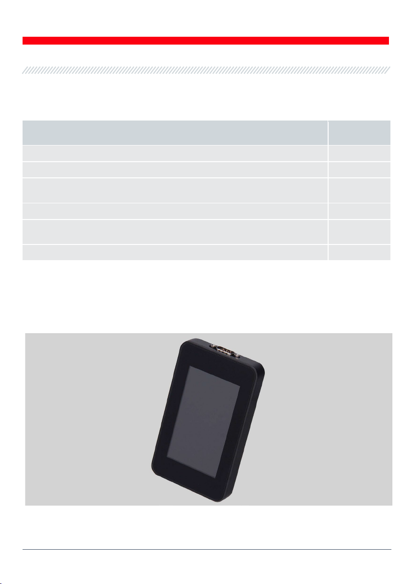
MSG Equipment MS016 User manual
Other MSG Equipment Test Equipment manuals

MSG Equipment
MSG Equipment MS121 User manual

MSG Equipment
MSG Equipment MS005 User manual

MSG Equipment
MSG Equipment MS300 User manual

MSG Equipment
MSG Equipment MS008 User manual

MSG Equipment
MSG Equipment MS1000+ User manual

MSG Equipment
MSG Equipment MS002 COM User manual

MSG Equipment
MSG Equipment MS021 User manual

MSG Equipment
MSG Equipment MS121 User manual

MSG Equipment
MSG Equipment MS031 User manual

MSG Equipment
MSG Equipment MS603N User manual


Popular Test Equipment manuals by other brands


Redtech
Redtech TRAILERteck T05 user manual

Venmar
Venmar AVS Constructo 1.0 HRV user guide

Test Instrument Solutions
Test Instrument Solutions SafetyPAT operating manual

Hanna Instruments
Hanna Instruments HI 38078 instruction manual

Kistler
Kistler 5495C Series instruction manual

Waygate Technologies
Waygate Technologies DM5E Basic quick start guide

StoneL
StoneL DeviceNet CK464002A manual

Seica
Seica RAPID 220 Site preparation guide

Kingfisher
Kingfisher KI7400 Series Training manual

Kurth Electronic
Kurth Electronic CCTS-03 operating manual

SMART
SMART KANAAD SBT XTREME 3G Series user manual

Agilent Technologies
Agilent Technologies BERT Serial Getting started