cetoni BASE 120 User manual

Base 120 / 600
Hardware Manual
ORIGINAL INSTRUCTIONS 2.09 –FEBRUARY 2021

2Base Module Hardware Manual
CETONI GmbH
Wiesenring 6
07554 Korbussen
Germany
T+49 (0) 36602 338-0
F+49 (0) 36602 338-11
www.cetoni.de

Base Module Hardware Manual 3
The information and data contained in this document are subject to change without notice. CETONI
GmbH is constantly striving to develop all its products. This means that there may be changes in form,
equipment and technology. Claims can therefore not be made on the basis of information, illustration or
descriptions in these instructions. The description for the product specification in this manual does not
constitute an integral part of the contract.
If you control the products with a software from CETONI GmbH, you agree to the applicable license
agreement, which can be read in the corresponding software manual. This and all other current product
manuals can be found at https://www.cetoni.com/service/manuals.
CETONI GmbH grants its customers the right to reproduce this manual for the purpose of providing
technical information to potential users of CETONI products. Extracts of these documents may only be
reproduced or transmitted with a precise reference to the authorship of CETONI GmbH, irrespective of
the manner in which they are reproduced or transmitted, either electronically or mechanically. Any
duplication or use of excerpts for other purposes requires the written permission of CETONI GmbH.
The general terms and conditions of CETONI GmbH shall apply. Alternative agreements must be in
written form.
Copyright © CETONI GmbH –Automation and Microsystems. All rights reserved.

4Base Module Hardware Manual

Base Module Hardware Manual 5
1Overviews and Indexes
1.1 Content
1Overviews and Indexes 5
1.1 Content 5
1.2 Change History 7
2Introduction 8
2.1 Foreword 8
2.2 Symbols and Key Words Used 8
2.3 Norms and directives 9
2.4 General Description of the Device 9
2.5 Intended Use 9
2.6 Reasonably Foreseeable Faulty Application 9
2.7 Safety Advice 10
3Scope of Supply 11
4Base Module Base 120 13
4.1 Hardware Operation 13
4.2 Technical Data 14
4.2.1 Mechanical Data 14
4.2.2 Electrical Data 14
4.2.3 Interfaces 14
4.2.4 Environment 14
5Base Module Base 600 15
5.1 Hardware Operation 15
5.2 Technical Data 17
5.2.1 Mechanical Data 17
5.2.2 Electrical Data 17

6Base Module Hardware Manual
5.2.3 Interfaces 17
5.2.4 Environment 17
6Extension Base Module Base 600XT 18
6.1 Hardware Operation 18
6.2 Technical Data 19
6.2.1 Mechanical Data 19
6.2.2 Electrical Data 20
6.2.3 Ambient Conditions 20
6.3 In-Line System Extension 20
6.4 Off-Line Power Supply 22
7Transportation and Storage 24
8Maintenance and Care 25
9Disposal 26

Base Module Hardware Manual 7
1.2 Change History
REV
DATE
CHANGE
VALID FOR
2.00
08.04.2015
Thematic splitting of the manual “Qmix
hardware”
date of purchase after 08.04.2015
2.01
11.03.2016
New corporate design
date of purchase after 08.04.2015
2.03
24.05.2017
New image material for new design of Base
120 and Base 600
date of purchase after 08.04.2015
2.04
08.09.2017
Legal notice updated
date of purchase after 08.04.2015
2.05
17.09.2017
Updated title
date of purchase after 08.04.2015
2.06
15.01.2020
Scope of supply added for Base 120 and Base
600
date of purchase after 08.04.2015
2.07
04.05.2020
Updated Change History layout
Added section Disposal
date of purchase after 08.04.2015
2.08
25.06.2020
Scope of supply adapted
date of purchase after 08.04.2015
2.09
26.02.2021
Images updated
date of purchase after 08.04.2015
IMPORTANT. In its current revision, this manual applies only to the product types
listed in the last line. Should you require a manual from a previous revision, please do not
hesitate to contact us. Please let us know your device type and email address and we will
send you the appropriate manual as a pdf file.
The type of your product can be found on the label behind "Type:" according to the marked number in
the following example:

8Base Module Hardware Manual
2Introduction
2.1 Foreword
Thank you for purchasing a product from CETONI. With this user manual we would like to support you
as well as possible when handling the device. If you have any questions or suggestions, please do not
hesitate to contact us.
2.2 Symbols and Key Words Used
The following symbols are used in this manual and are designed to aid your navigation through this
document:
HINT. Describes practical tips and useful information to facilitate the handling of the
software.
IMPORTANT. Signifies important hints and other useful information that may not
result in potentially dangerous or harmful situations.
ATTENTION. Indicates a potentially harmful situation. If it is not avoided, the product
or something in its environment may be damaged.
CAUTION. Indicates a potentially dangerous situation. If it is not avoided, slight or
minor injuries and property damage may result.

Base Module Hardware Manual 9
2.3 Norms and directives
CETONI GmbH declares under its sole responsibility, that the device complies with the
health and safety requirements of the relevant European directives.
2.4 General Description of the Device
The base modules Base 120, Base 600 und Base 600XT are used to supply a CETONI system with a
supply voltage of 24V. Base 120 and Base 600 also provide a USB interface for connection to a PC.
2.5 Intended Use
The base modules Base 120, Base 600 und Base 600XT are to be used for the appropriate CETONI
GmbH laboratory devices. Application usually takes place in laboratory-like rooms.
2.6 Reasonably Foreseeable Faulty
Application
A use for applications distinct from the intended purpose can lead to dangerous situations and is to be
omitted.
CAUTION. The unit must not be used as a medical device or for medical purposes.

10 Base Module Hardware Manual
2.7 Safety Advice
For the safe operation of a base module, it is essential to observe the safety measures in the CETONI
System manual.
IMPORTANT. Please read this manual as well as the related software manual carefully
and completely before putting your Qmix system into operation.
Additionally please read the CETONI System manual carefully and completely before
putting your system into operation.

Base Module Hardware Manual 11
3Scope of Supply
The delivery of the Base 120 and Base 600 should include the following items in addition to the unit
itself (does not apply to BASE 600 XT):
COUNTRY SPECIFIC POWER CABLE FOR NON-
HEATING APPARATUS
USB CABLE
INTERCONNECT CABLE 0,5m
BUS TERMINATING PLUG

12 Base Module Hardware Manual
HARDWARE-MANUAL AND CD WITH SOFTWARE-
MANUAL, SOFTWARE AND DRIVERS

Base Module Hardware Manual 13
4Base Module Base 120
4.1 Hardware Operation
The base module supplies all other modules with power and serves as an interface to your PC.
The Base 120 base module can continuously supply a power of 120 W. In the section
technical data →electrical data you can find the power consumption of every module you may want to
connect. Please make sure that the total power consumption of the assembly must not exceed the
power supply capability of the base module. In case of overload the base module will deactivate itself
and all connected devices and you will lose control of your application.
Should the power supply capacity of the Base 120 base module be insufficient, you may also use the
Base 600 base module or the Base 600XT extension.
CAUTION. Danger of sudden deactivation! Make sure that the total power consumption
of all connected devices does not exceed the power supply capacity of the base module.
On one side of the device there is a power connector with a fuse box. A replacement fuse (Ø5x20mm)
can be found in the same box. The rated current of the fuse may vary depending on the country of use
and can be seen on the type plate.
The power switch is located to the right of the power socket and will light up red when the device is
turned on. The type B USB-connector is used to connect the device to your PC.
USB-socket (type B)
Power Socket
Fuse
Power Switch
Type Plate

14 Base Module Hardware Manual
4.2 Technical Data
4.2.1 Mechanical Data
DIMENS ION (L X B X H)
310 x 100 x 56 mm
WEIGH T
≈1800 g
4.2.2 Electrical Data
SUPPLY VOLT AGE
90 ~ 260VAC
FREQUENCY
47 ~ 63 Hz
POWER OUTPU T
24VDC; 5A; 120 W
4.2.3 Interfaces
USB
1.1 und 2.0
4.2.4 Environment
OPERATING TEM PERATUR E
0°C to 50°C
STORAGE TEM PERATURE
-20°C to 75°C
OPERATING / STORAGE AIT HUMIDITY
20% to 90%, non-condensing

Base Module Hardware Manual 15
5Base Module Base 600
5.1 Hardware Operation
The Base Module supplies all connected modules with electricity and serves as an interface to your PC.
The Qmix Base Module can provide a maximum power output of 650W permanently. For any module
you connect, the power consumption value can be found in the section
Technical Data →Electrical Data. Please observe that the total power consumption of all connected
modules does not exceed the power output of the Base module. The Base module and all connected
Modules will switch off in the event of an overload and you will no longer have the control over your
application.
Instead of the Qmix Base Module you can also use the smaller NEMESYS Base module, which has as
maximum power output of 120W.
CAUTION. Risk of sudden shut down! Observe that the total power consumption of all
connected modules does not exceed the power output of the Base module.
The mains connection including the fuse compartment is located on the side of the device. A
replacement fuse (Ø5x20mm) can be found in the same compartment. The rated current of the fuse can
vary between countries and is specified on the type plate.
Mains switch
USB-Port Type B
Ventilation Grille
Type Plate
Fuse
Mains Connection

16 Base Module Hardware Manual
The mains switch is located to the right of the mains connection. It will light up red when the device is
connected and switched on.
The USB-port (type B) is used to connect the Qmix system with your PC.
Pay attention not to cover the ventilation grilles. Otherwise the device might switch off to avoid
damage due to overheating. This would happen unexpectedly and without an advance warning.
On one side there are additional ventilation slots on the base plate of the device. The ventilation grilles
on this side may be covered, for instance for upright use, as long as the ventilation slots allow free air
flow (as shown in the following picture).
LüftungsschlitzeVentilation slots

Base Module Hardware Manual 17
5.2 Technical Data
5.2.1 Mechanical Data
DIMENS ION (L X B X H)
310 x 200 x 56 mm
WEIGH T
≈3700 g
5.2.2 Electrical Data
SUPPLY VOLT AGE
90 ~ 260VAC
FREQUENCY
47 ~ 63 Hz
POWER OUTPU T
24VDC; 27A; 650 W
5.2.3 Interfaces
USB
1.1 und 2.0
5.2.4 Environment
OPERATING TEM PERATUR E
0°C to 50°C
STORAGE TEM PERATURE
-20°C to 75°C
OPERATING / STORAGE AIT HUMIDITY
20% to 90%, non-condensing

18 Base Module Hardware Manual
6Extension Base Module Base
600XT
6.1 Hardware Operation
The Extension Base Module is used if the power of the normal Base Module is not sufficient to feed
your entire system with energy. It also provides a maximum power of 650 W.
For any module you connect, the power consumption value can be found in the section Technical Data
of the appropriate manual. Please observe that the total power consumption of all connected modules
does not exceed the power output of the Extension Base Module. The Extension Base Module and all
connected Modules will switch off in the event of an overload and you will no longer have the control
over your application.
CAUTION. Risk of sudden shut down! Observe that the total power consumption of all
connected modules does not exceed the power output of the Base module.

Base Module Hardware Manual 19
The Extension Base Module can only be operated in connection with an existing system. It automatically
turns on and off with this.
The connections of the Extension Base Module are explained below:
NO.
DESCRIPTION
1
Mains connection with fuse (Ø5x20mm see type plate)
2
Connector for connection to the base system via Interconnect cable
3
Display for the current power output (650W max.)
4
Three connectors for off-line loads (450W max. per connector)
5
Connector for additional modules (on opposite side)
6.2 Technical Data
6.2.1 Mechanical Data
DIMENS IONS (L X B X H)
310 x 200 x 56 mm
WEIGH T
≈3700 g
1
2
3
4
5

20 Base Module Hardware Manual
6.2.2 Electrical Data
SUPPLY VOLT AGE
90 ~264VAC
FREQUENCY
47 ~63 Hz
POWER OUTPU T
24VDC; 27A; 650 W
6.2.3 Ambient Conditions
OPERATING TEM PERATUR E
0°C to 50°C
STORAGE TEM PERATURE
-20°C to 75°C
OPERATING / STORAGE AIT HUMIDITY
20% to 90%, non-condensing
The extension base module can be used in two different ways, which are explained below:
6.3 In-Line System Extension
In the case of in-line system extension, the Extension Base Module is connected to an existing base
system via an interconnect cable. Now additional modules can be connected to the Extension Base
Module as usual (see general part of the manual, section “Connection of additional modules”). The
entire system is controlled by the PC, which is connected to the Base Module of the base system. The
Extension Base Module automatically switches on and off together with the Base Module of the base
system.
Base-Module
Module 1
Module 2
Module 3
Base System
Interconnect cable
Extension-
Base-Module
Module 4
Module 5
Module 6
System Extension
Entire System
Other manuals for BASE 120
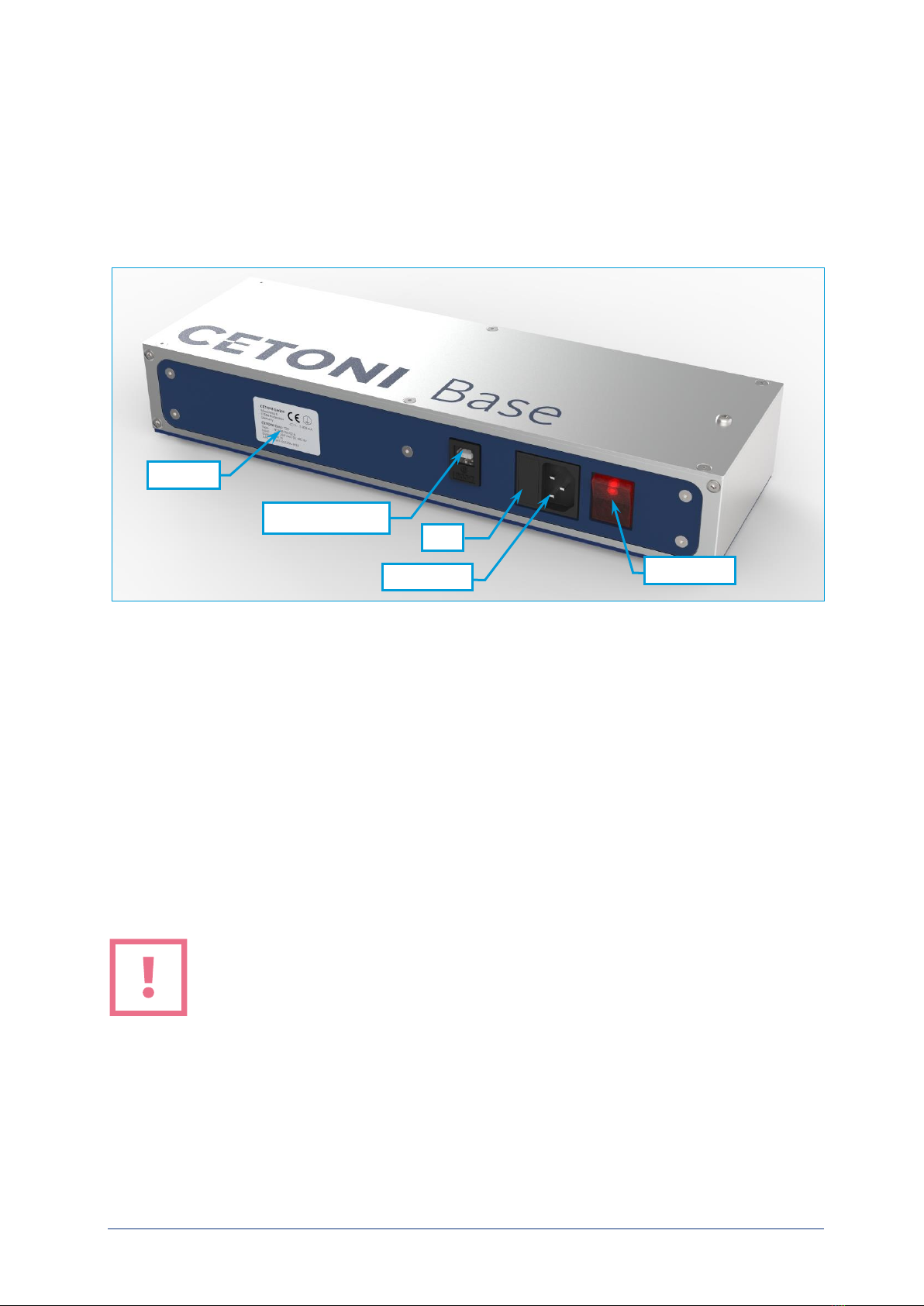
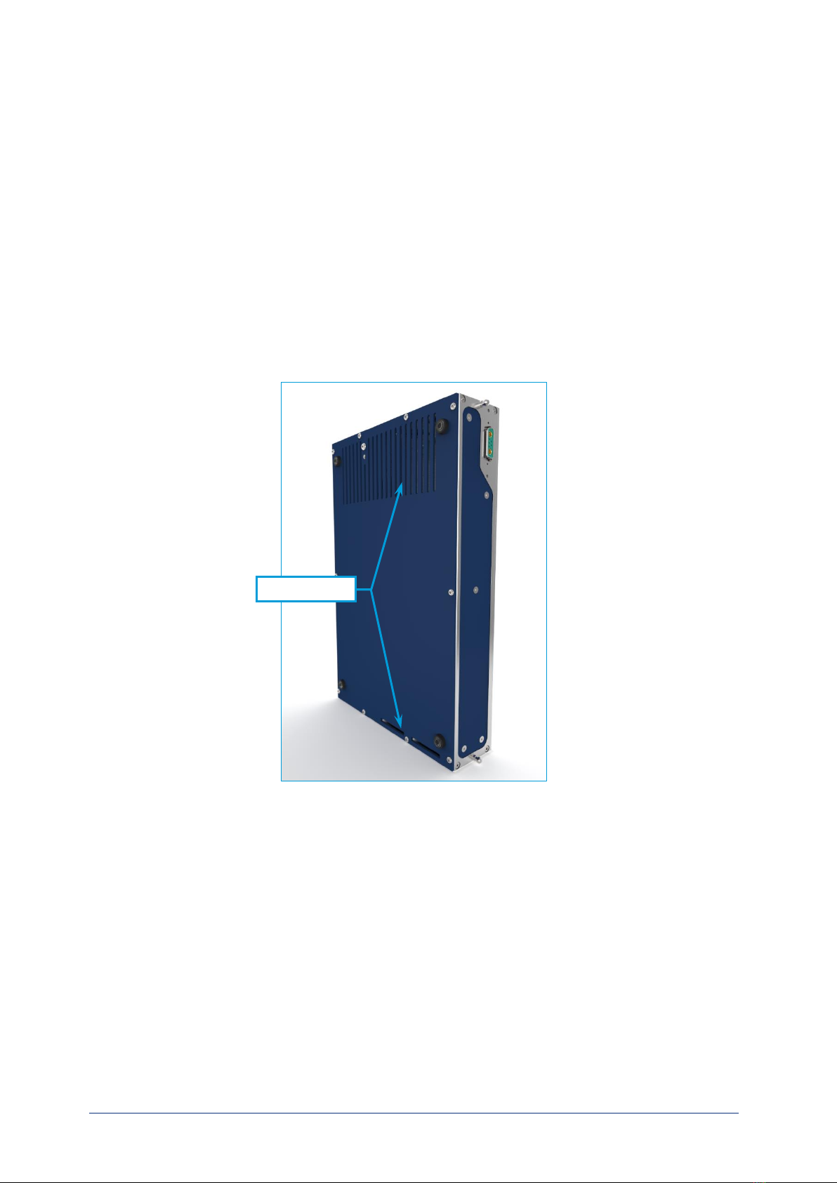
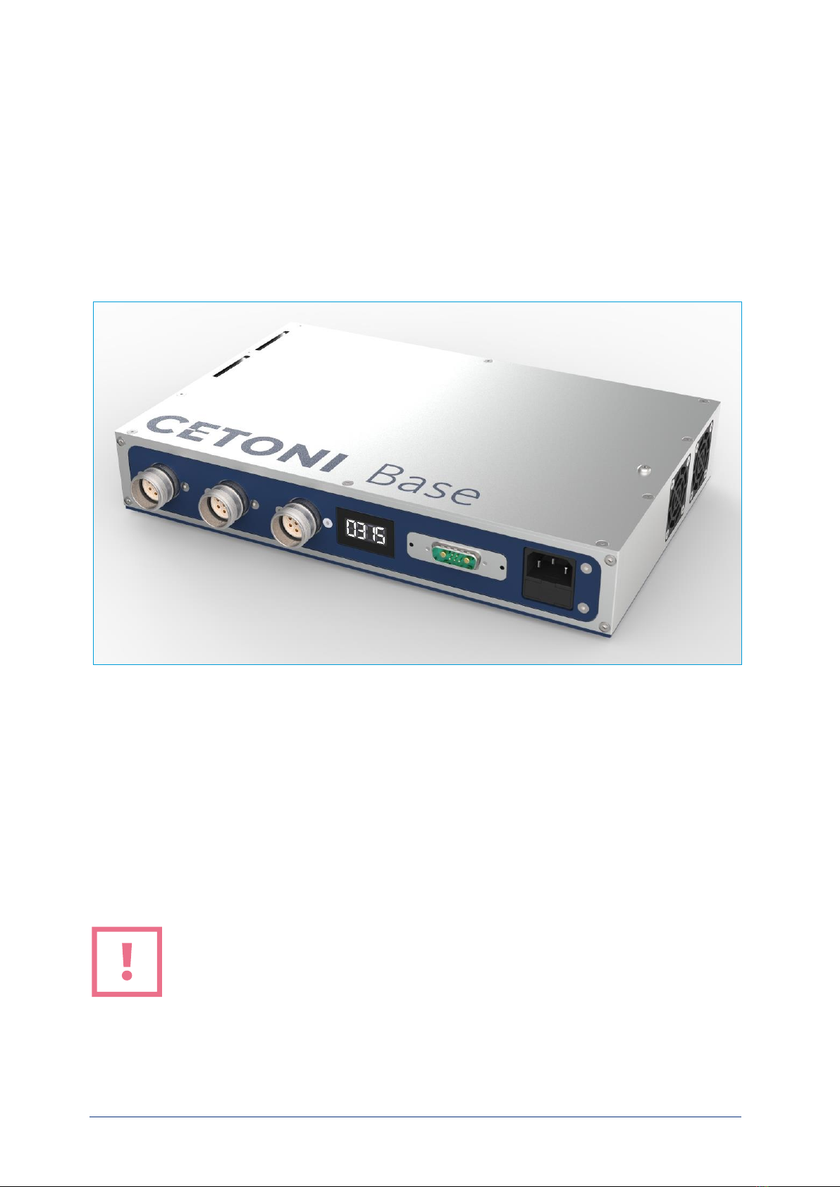
2
This manual suits for next models
1
Table of contents
Other cetoni Laboratory Equipment manuals
Popular Laboratory Equipment manuals by other brands

Leica BIOSYSTEMS
Leica BIOSYSTEMS Aperio AT2 DX user guide

Cannon
Cannon CCS-2100 instruction & operation manual

Awareness Technology
Awareness Technology Stat Fax 4700 Operator's manual

MOGlabs
MOGlabs MWM manual

Pure Humidifier
Pure Humidifier Fast-Pac Installation and assembly instructions

MELAG
MELAG Carebox Blue user manual