Ceyear 1465 Series User manual
1465 Series
Signal Generator
User Manual
China Electronics Technology Instruments Co., Ltd

This manual applies to signal generators of models below and based on firmware version 1.0 and above.
1465A signal generator (100kHz ~ 3GHz)
1465B signal generator (100kHz ~ 6GHz)
1465C signal generator (100kHz ~ 10GHz)
1465D signal generator (100kHz ~ 20GHz)
1465F signal generator (100kHz ~ 40GHz)
1465H signal generator (100kHz ~ 50GHz)
1465L signal generator (100kHz ~ 67GHz)
1465A-V signal generator (100kHz ~ 3GHz)
1465B-V signal generator (100kHz ~ 6GHz)
1465C-V signal generator (100kHz ~ 10GHz)
1465D-V signal generator (100kHz ~ 20GHz)
1465F-V signal generator (100kHz ~ 40GHz)
1465H-V signal generator (100kHz ~ 50GHz)
1465L-V signal generator (100kHz ~ 67GHz)
Version: A.3 September 2018, China Electronics Technlogy Instruments Co., Ltd
Address: No.98, Xiangjiang Road, Qingdao City, China
Tel: +86-0532-86896691
Website: www.ceyear.com
E-mail: sales@ceyear.com
Postal code: 266555

Foreword
Thank you for choosing the
1465 series signal generator
developed and manufactured
by China Electronics
Technology Instruments Co.,
Ltd (CETI). Our product is
high-end, precise and
sophisticated, and embraces a
high cost performance among
the competitors of the same
class.
We are devoted to providing for
you high-quality products and
first-class after-sales service
with your most concerns and
demands in mind. Our
consistent aim is providing
excellent quality and good
service, and this is our sincere
commitment for all users.
Manual No.
AV2.827.1202SSEN
Version
A.32018.9
China Electronics Technology
Instruments Co., Ltd
Manual Authorization
This manual may be subject to
change without notice. CETI
reserves all the rights to the
final explanation for all the
information and terminologies
referred to in this manual.
This manual is the property of
CETI. Without CETI's
permission, any organizations
or individuals shall neither alter
nor duplicate/transmit this
manual for profits; otherwise,
CETI reserves the right to
pursue any liabilities therefrom.
Product Warranty
The warranty period of this
product is 18 months from the
date of delivery. Instrument
manufacturer will repair or
replace the damaged parts
according to the actual
situation in the warranty period.
The specific maintenance
matters should be subject to
the contract.
Product Quality
Certification
This product is certified to fulfill
the standards indicated in this
manual from the day of delivery.
Calibration measurements
have been carried out based on
national standards. Related
information is available to the
user for reference.
Quality/Environmental
Management
The quality and environmental
management systems have
always been implemented
during development,
manufacturing and test of this
product. China Electronics
Technology Instruments Co.,
Ltd (CETI) has been properly
qualified and certified ISO 9001
and ISO 14001 management
system standards.
Safety Precautions
WARNING indicates a danger.
It reminds the user to be
cautious of a certain operation
process, operation method or
the similar. Failure to follow the
rules or operate correctly may
result in the personal injury.
The conditions indicated by
WARNING should be fully
understood and met before the
next operation.
ATTENTION indicates an
important information rather
than a danger. It reminds the
user to be cautious of a certain
operation process, operation
method or the similar. Failure to
follow the rules or operate
correctly may cause the
damage to the instrument or
loss of important data. The
conditions indicated by
CAUTION should be fully
understood and met before the
next operation.
CAUTION
WARNING
!


1465 series signal generator
Table of Contents
1
Table of Contents
1 About This Manual ..................................................................................................1
1.1About This Manual......................................................................................................................1
1.2Related Documents....................................................................................................................2
2 Overview...................................................................................................................5
2.1General.........................................................................................................................................5
2.1.1 Product features............................................................................................................................ 5
2.1.2 Typical Applications.................................................................................................................... 11
2.2Safety guide...............................................................................................................................12
2.2.1 Safety signs................................................................................................................................. 13
2.2.2 Operation status and position................................................................................................... 14
2.2.3 Electrical safety........................................................................................................................... 14
2.2.4 Operation precautions................................................................................................................ 15
2.2.5 Maintenance................................................................................................................................ 15
2.2.6 Battery or power module............................................................................................................ 15
2.2.7 Transportion................................................................................................................................. 16
2.2.8 Disposal/environmental protection........................................................................................... 16
3 Start Guide..............................................................................................................17
3.1 Preparation before Use............................................................................................................17
3.1.1 Preparations before operation.................................................................................................. 17
3.1.2 Configuration of operating system ........................................................................................... 27
3.1.3 Routine maintenance................................................................................................................. 32
3.2Description of front and rear panels.......................................................................................33
3.2.1 Description of front panel........................................................................................................... 33
3.2.2 Description of rear panel............................................................................................................ 35
3.3 Basic configuration method.....................................................................................................37
3.3.1 Description of basic settings ..................................................................................................... 37
3.3.2 Example of operation.................................................................................................................. 42
3.3.3 Description of main configuration scenarios........................................................................... 51
3.4 Data management....................................................................................................................58
3.4.1 Saving/loading of working state................................................................................................ 59
3.4.2 File management........................................................................................................................ 60
3.4.3 Printing/saving of screenshot.................................................................................................... 63

1465 series signal generator
Table of Contents
2
4 Operation Guides..................................................................................................65
4.1 Basic operation guides.............................................................................................................65
4.1.1 Digital modulation....................................................................................................................... 65
4.1.2 Simulation modulation and pulse modulation......................................................................... 66
4.1.3 Sweep........................................................................................................................................... 69
4.2 Advanced operation guides ....................................................................................................72
4.2.1 Configuring multi-tone................................................................................................................ 72
4.2.2 ARB configuration....................................................................................................................... 74
4.2.3 Selecting ALC bandwidth .......................................................................................................... 80
4.2.4 External level control.................................................................................................................. 81
4.2.5 Working with a frequency mixer/Effects of reverse power ................................................... 82
4.2.6 Creating and applying a user flatness correction array ........................................................ 83
4.2.7 Selecting pulse modulation input.............................................................................................. 84
4.2.8 Baseband trigger function configuration.................................................................................. 87
4.2.9 Arbitrary waveform triggering function configuration............................................................. 90
5 Menu........................................................................................................................95
5.1 Menu Structure and Parameter Settings ..............................................................................95
5.1.1 Frequency.................................................................................................................................... 95
5.1.2 Amplitude..................................................................................................................................... 97
5.1.3 Sweep........................................................................................................................................... 99
5.1.4 Modulation.................................................................................................................................. 101
5.1.5 Base............................................................................................................................................ 107
5.1.6 I/Q................................................................................................................................................ 109
5.1.7 ARB............................................................................................................................................. 110
5.1.8 Tone............................................................................................................................................ 112
5.1.9 AWGN (Option)......................................................................................................................... 113
5.1.10 System...................................................................................................................................... 114
5.1.11 File ............................................................................................................................................ 118
5.1.12 Save/Recall.............................................................................................................................. 118
5.1.13 Calibrate................................................................................................................................... 119
5.2 Menu Description....................................................................................................................120
5.2.1 Frequency.................................................................................................................................. 120
5.2.2 Ampl............................................................................................................................................ 125

1465 series signal generator
Table of Contents
3
5.2.3 Sweep......................................................................................................................................... 131
5.2.4 Modulation.................................................................................................................................. 137
5.2.5 Base............................................................................................................................................ 144
5.2.6 I/Q................................................................................................................................................ 149
5.2.7 ARB............................................................................................................................................. 156
5.2.8 Tone............................................................................................................................................ 163
5.2.9 AWGN (Option)......................................................................................................................... 166
5.2.10 System...................................................................................................................................... 169
5.2.11 File ............................................................................................................................................ 171
5.2.12 Save/Recall.............................................................................................................................. 172
5.2.13 Calibrate................................................................................................................................... 172
6 Remote Control....................................................................................................175
6.1Remote control basis..............................................................................................................175
6.1.1 Remote Interface ...................................................................................................................... 175
6.1.2 Message..................................................................................................................................... 178
6.1.3 SCPI............................................................................................................................................ 178
6.1.4 Command Sequence and Synchronization .......................................................................... 186
6.1.5 Status reporting system........................................................................................................... 187
6.1.6 Programming considerations.................................................................................................. 189
6.2Remote interface and its configuration................................................................................189
6.2.1 LAN............................................................................................................................................. 189
6.2.2 GPIB............................................................................................................................................ 190
6.3Basic programming method of the VISA interface.............................................................191
6.3.1 VISA library................................................................................................................................ 191
6.3.2 Initialization and default status setting................................................................................... 192
6.3.3 Sending of set command......................................................................................................... 193
6.3.4 Reading of instrument configuration...................................................................................... 193
6.3.5 Synchronization of command.................................................................................................. 194
6.4I/O library..................................................................................................................................195
6.4.1 Overview of I/O library.............................................................................................................. 195
6.4.2 Installation and configuration of I/O library ........................................................................... 196
7 Fault Diagnosis & Repair...................................................................................197
7.1 Operating principle .................................................................................................................197

1465 series signal generator
Table of Contents
4
7.1.1 Instrument operating principle & functional block diagram of hardware........................... 197
7.2 Fault diagnosis and troubleshooting....................................................................................199
7.2.1 System issue............................................................................................................................. 199
7.2.2 Unlocked hardware................................................................................................................... 199
7.2.3 Unfixed amplitude..................................................................................................................... 201
7.2.4 Cold timebase............................................................................................................................ 201
7.2.5 RF output power issue............................................................................................................. 202
7.2.6 RF output port unmodulated ................................................................................................... 202
7.2.7 Sweeping issue......................................................................................................................... 203
7.2.8 Data storage issue.................................................................................................................... 203
7.2.9 Unresponsive front panel keys ............................................................................................... 203
7.2.10 Remote control issue............................................................................................................. 203
7.3 Error information.....................................................................................................................204
7.3.1 Error information file................................................................................................................. 204
7.3.2 Error information description................................................................................................... 204
7.4 Repair methods.......................................................................................................................205
7.4.1 Contact us.................................................................................................................................. 205
7.4.2 Packaging and transport.......................................................................................................... 206
8 Specifications and Test Methods......................................................................207
8.1 Statement.................................................................................................................................207
8.2 Product Features....................................................................................................................207
8.3 Specifications..........................................................................................................................208
8.4 Option Information..................................................................................................................218
8.5 Supplementary Information...................................................................................................220
8.5.1 General Information.................................................................................................................. 220
8.6 Performance Characteristics Test........................................................................................222
8.6.1 Recommended test method.................................................................................................... 222
8.6.2 Performance characteristics test record table...................................................................... 235
8.5.3 Recommended instruments for performance characteristics test..................................... 246
Appendixes..............................................................................................................247
Appendix A Explanations of Terms............................................................................................247
Frequency accuracy........................................................................................................................... 247
Frequency stability.............................................................................................................................. 247
Harmonic distortion and spectrum purity......................................................................................... 247

1465 series signal generator
Table of Contents
5
I/Q modulation..................................................................................................................................... 248
Speech coding..................................................................................................................................... 248
Channel coding................................................................................................................................... 249
Digital modulation............................................................................................................................... 249
Frequency band utilization of digital modulation signals .............................................................. 250
Binary frequency shift keying 2FSK................................................................................................. 250
Binary phase shift keying BPSK....................................................................................................... 250
Quadrature phase shift keying QPSK.............................................................................................. 251
8 phase shift keying 8PSK ................................................................................................................ 251
Quadrature amplitude modulation QAM.......................................................................................... 252
Differential modulation method π/4DQPSK.................................................................................... 252
QPSK modulation method................................................................................................................. 253
Constant envelope digital modulation MSK (minimum shift keying)........................................... 253
3π/8 rotation 8PSK modulation (EDGE) ......................................................................................... 254
Nyquist filter......................................................................................................................................... 254
Nyquist filter coefficient α................................................................................................................... 255
Appendix B Lookup Table of SCPIs...........................................................................................256
Appendix C Lookup Table of Error Information........................................................................273
Appendix D Lookup Table of PC Keyboard in Function Configuration Windows ...............274


1 bout This Manual
1.2 Related Documents
1
1 About This Manual
This chapter introduces the function, compositions and main content of the User Manual of the 1465
series signal generator as well as other related documents provided to the user.
About This Manual ……………………………………………………………………………………1
Related Documents ……………………………………………………………………………………2
1.1 About This Manual
This manual introduces the basic functions and operation methods of the 1465 series signal
generator and describes the features, basic usage, measurement, configuration and operation guides,
menus, remote control, maintenance, specifications and test methods of the instrument to help you
familiarize yourself with and master the operation methods and essentials as soon as possible. To
facilitate your familiarity with the instrument, please read this manual carefully before operating the
instrument, and then follow the instructions of manual.
The chapters included in this User Manual are as follows:
Overview
This chapter generally introduces the main performance characteristics, typical application cases
and operational safety precautions of the 1465 series signal generator, so that the user can know about
the main performance characteristics of the instrument and operate the instrument safely in accordance
with the instructions.
Start Guide
This chapter introduces the preoperational check, instrument overview, basic method of
configuration, and the method to use the configuration dialog and store data for the 1465 series signal
generator. Allow the user to know about the instrument and configuration process and make preliminary
preparations for comprehensive introduction of configuration and operation guides of the instrument.
The content contained in this chapter is consistent with that in relevant chapters of Quick Start Guide.
Operation Guide
This chapter detailedly introduces the operation methods of various configuration functions of the
instrument, including configuration, configuration process start and configuration result acquisition. This
chapter falls into two parts: Basic operation guide and advanced operation guide. The basic operation
guide is intended for users unfamiliar with the way to use the instrument, and systematically introduces
and enumerates each function in detail, to help users understand and master basic usage of the
instrument, such as setting of CW, amplitude, modulation, etc. The advanced operation manual is
prepared for users who have general knowledge about the use of signal generator but are not familiar
with some special usages. It introduces the relatively complicated test process and high-level use
techniques and guides the user to implement the operation process, For example: List configuration of
step sweep and list sweep, generation of vector signal, etc.
Menu
This chapter introduces the menu structure and items by function for user‘s query and reference.
Remote Control
This chapter introduces the remote control methods of the instrument so that the user can rapidly
master the method to control the instrument in a remote way. It is further divided into the following four
sections: remote control basis, which introduces the concepts related to remote control, software
configuration, remote interface, SCPI, etc.; instrument interface configuration methods, which introduces
the remote interface connection methods and software configuration methods of the 1465 series
microwave power meter; basic programming methods of the VISA interface, which gives a basic
programming example in the form of text description plus programming examples so that the user can
quickly grasp the programming methods; the I/O function library, which introduces the basic concept of
the instrument driver and the basic installation and configuration of the IVI-COM/IVI-C driver.
Fault Diagnosis and Repair

1 bout This Manual
1.2 Related Documents
2
This chapter introduces the working principles, fault diagnosis and troubleshooting methods, error
message description and repair methods of the unit.
Specifications and Test Methods
This section introduces the product features, main specifications and recommended test method of
the 1465 series signal generator.
Appendixes
This section lists the related reference information of the 1465 series signal generator, including:
terminology, look-up table of programming command, look-up table of error message.
1.2 Related Documents
The product documents related to 1465 series signal generator include:
Quick Start Guide
Online support
User Manual
Programming Manual
Quick Start Guide
This guide presents the instrument configuration and basic method of initiating configuration, and
aims to facilitate a quick understanding of instrument features, a mastery of basic setting, basic
operation method of local and remote control. Main chapters included in this manual are as follows:
Preparation before Use
Typical Applications
Getting Help
User Manual
This manual introduces in detail features and operation methods of the instrument, including:
configuration, remote control and maintenance. for the purpose of guiding the user to fully understand
the features of the product and master the common instrument test methods. The chapters included in
this manual are as follows:
About This Manual
Overview
Start Guide
Operation Guide
Menu
Remote Control
Fault Diagnosis and Repair
Specifications and Test Methods
Appendixes
Programming Manual
This manual elaborates the programming fundamentals of remote control, SCPI basics, SCPI,
programming examples and I/O driver function library, for the purpose of guiding the user to master the
SCPIs and methods of the instrument quickly and comprehensively. The chapters included in this
manual are as follows:
Remote Control
SCPI

1 bout This Manual
1.2 Related Documents
3
Programming Examples
Error Description
Appendixes
Online support
Online help is integrated in the instrument product to provide quick text navigation help for user local
and remote control operation. The hard keys on the instrument front panel or the user interface toolbars
may be activated with their corresponding shortcut keys. The contents are the same as those in the user
manual.

1 bout This Manual
1.2 Related Documents
4

2 Overview
2.2 General
5
2 Overview
This chapter introduces the product features, main scope of application and specifications. Also, it
describes how to properly operate the instrument and electrical safety precautions.
General …………………………………………………………………………………………………5
Safety guide …………………………………………………………………………………………12
2.1 General
The 1465 series signal generator has a frequency range of 100kHz ~ 67GHz, excellent spectrum
purity and output power, with SSB phase noise of 10GHz carrier @ 10kHz frequency offset of -
126dBc/Hz, max. output power up to 1W@20GHz, power dynamic range greater than 150dB which can
meet high demands for test signals; it also features high-precision analog sweep function, excellent
simulation modulation, pulse modulation and vector modulation; the baseband signal generator is easily
set up and flexible, and supports multiple modulation formats, alllowing users to edit and download the
required waveform for signal simulation based on individual needs; the internal and external vectors
have wide modulation bandwidth (internal 200MHz and external 2GHz) which can meet the needs of
broadband signal simulation; the internal modulation signal generator has frequency up to 10MHz and
multiple signal waveforms, pulse modulation supports minimum PW of 20ns and generates flexible pulse
trains that can satisfy the needs for testing various complex signals; the product has a 10.1″ large
display with resolution of 1280×800 and can be operated by keys, a mouse or screen touch, improving
the operating experience while enhancing the testing efficiency. The 1465 series generates high-quality
signals in both continuous wave and modulation, making it an ideal local oscillator and clock source, and
a high-performance simulation signal source. It is mainly used for comprehensive assessment of radar
performance, high-performance receiver testing and component parameter testing, applicable for many
fields such as aerospace, radar, communication, navigation equipment, etc.
Product features ………………………………………………………………………………………5
Typical application ……………………………………………………………………………………11
2.1.1 Product features
2.1.1.1 Basic function
The 1465 series signal generator developed by CETI embraces the following main features:
1) Three basic modes of signal output: Continuous wave (CW) signal, sweep signal and digital
modulation signal.
Continuous wave (CW) signal
In this mode, the instrument generates a CW sine signal with the frequency and power
level defined by the user.
Sweep signal
Basic sweep outputs are provided, including step sweep, list sweep and ramp sweep.
Multiple sweep triggering inputs and outputs are provided.
High-precision broadband vector modulation signal output
If an internal baseband is used in the 1465-V signal generator, vector modulation signals of
bandwidth up to 200MHz can be generated; when an external I/Q is used, the modulation
bandwidth is 200MHz, supporting broadband I/Q input of external arbitrary waveform
generator, with RF modulation bandwidth up to 2GHz.
2) Generation of internal broadband and multi-system baseband signals. The vector signal
generator can produce digital modulation (real-time) baseband signals, with single-channel
bandwidth up to 100MHz.
3) External reference clock (ERCLK) input of baseband, and synchronous input of external data
source.
4) Storage and calling of instrument set state, and one-button self test.

2 Overview
2.2 General
6
5) Including GPIB, LAN, and other I/O remote interfaces;
2.1.2.2 High performance
1) Excellent spectrum purity
The 1465 series signal generator can generate high-purity signal spectrum, of SSB phase noise
10GHz carrier@10kHz frequency offset (typical value) -126dBc/Hz, 1GHz carrier@10kHz frequency
offset (typical value) -142dBc/Hz, making it applicable for testing of Doppler radar, high-performance
receiver blocking and adjacent channel selectivity, and an ideal alternative of local oscillator and
low-jitter clock.
Fig. 2.1 SSB Phase Noise
2) Broadband high power output
Typical value of max. output power of H05 high power option: +22dBm @ 20GHz, +20dBm @
40GHz (-V series: +16dBm), +10dBm @ 67GHz (-V series: +6dBm). H06 enhanced high power option
has output power up to 30dBm (1W). During testing, high power excitation signals, if required, can be
obtained without connecting to an external amplifier, and the power has higher accuracy and stability.
Fig. 2.2 Max. Output Power of 1465D+H06
20
22
24
26
28
30
32
34
36
0 5 10 15 20
Power/dBm
Frequency/GHz
1465D Max. Output Power (Option H06)
SSB Phase Noise Option H04
Frequency offset

2 Overview
2.2 General
7
Fig. 2.3 Max. Output Power of 1465F+H05
Fig. 2.4 Max. Output Power of 1465F-V+H05
3) High-vector modulation bandwidth
The 1465-V series can generate vector signals of modulation bandwidth 200MHz and 2GHz
external (> 3.2GHz carrier).
Fig. 2.5 5GHz Carrier 200MHz Modulation Bandwidth Multi-tone Signal
10
12
14
16
18
20
22
24
26
28
30
0 5 10 15 20 25 30 35 40
Power/dB m
Frequency /GHz
1465F Max. Output Power (Option H05)
10
12
14
16
18
20
22
24
26
28
30
0 5 10 15 20 25 30 35 40 45
Power/dB m
frequency/GHz
1465F-V Max . Output Power(Option H05)
2 Overview
2.2 General
8
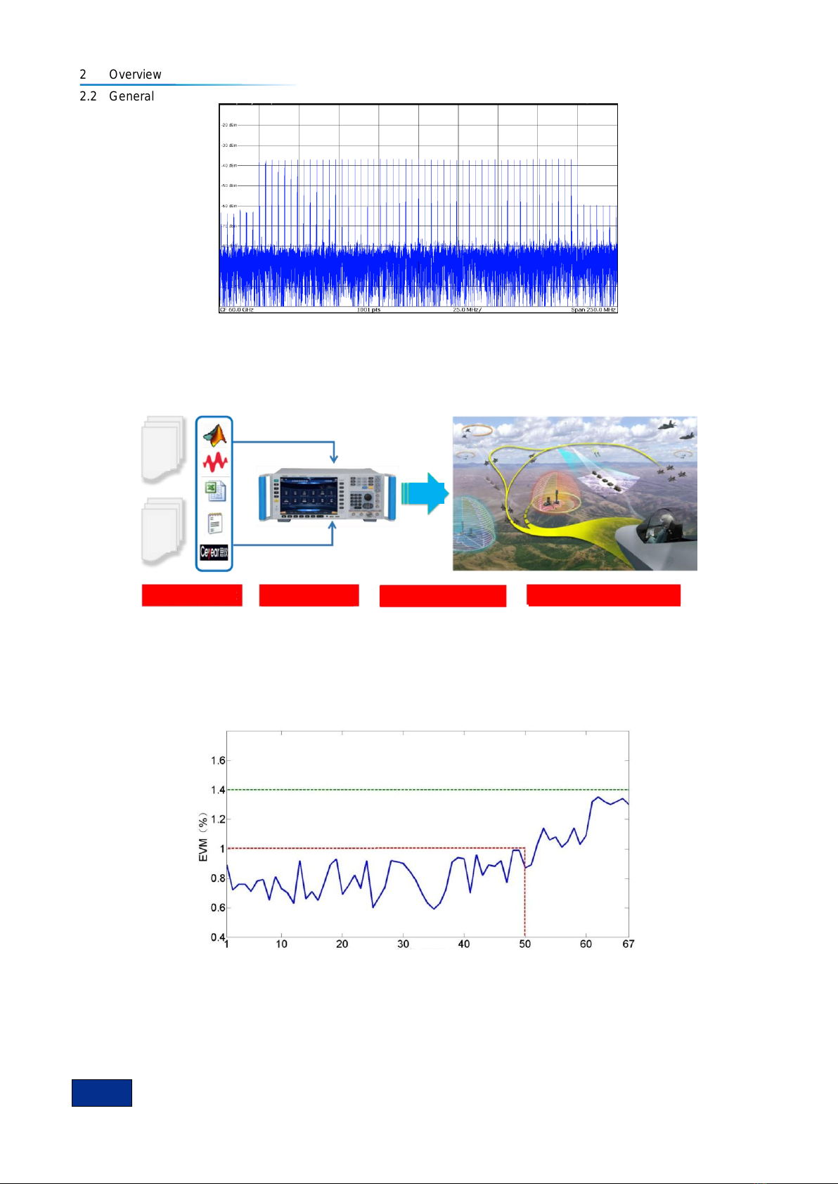
Fig. 2.6 60GHz Carrier 200MHz Modulation Bandwidth Multi-tone Signal
4) Download of high-compatibility arbitrary waveform data format
The 1465-V series supports downloading and playing of arbitrary waveform data in storage formats
of Mat-File 5,ASCII, Binary, cap, csv and up to the depth of 2G sampling point.
Fig. 2.7 Downloading and Playing of Arbitrary Waveform Data
5) Vector modulation accuracy
The 1465-V series has high vector modulation accuracy of EVM<1.4% (test value<1.0% for 100kHz
~ 40GHz) and EVM<2.5% (test value<1.5% for 40GHz ~ 67GHz).
Fig. 2.8 Vector ModulationAccuracy
6) Universal digital modulation in complete formats
The 1465-V series supports real-time generation of universal digital modulation signals in more than
20 formats including PSK, QAM, FSK, MSK, etc.
Frequency (GHz)
Data
simulati
on and
generat
ion
5 data formats
Storage depth of 2G
sampling point
Flexible and controllable
playing
Simulation and reproduction of
complex electromagnetic situation
USB copy
Remote control
connection
Live
data
recordi
ng
Downloading
and playing

2 Overview
2.2 General
9
Fig. 2.9 8PSL Fig. 2.10 512QAM
7) Complete series of frequency band
Based on specific demands of different users, the 1465 series signal generator can provide various
test plans for upper frequency limits of 3GHz/6GHz/10GHz/20GHz/40GHz/50GHz/67GHz, and there are
signal generators of common type and with vector modulation function (-V series) for each frequency
band, i.e. totally 14 types of this series. Each type has many options for function and performance
extensions. From measuring-level solutions to basic types, whether you only need test signals of RF
band or of MMW frequency, we guarantee a suitable one for you.
2.1.1.3 Flexibility
1) Large-screen TFT LED gives graphical display and supports operation by screen touch
and front-panel keys.
The 1465 series signal generator is applied with self-designed software, a large screen and a
Chinese/English operation interface to provide a panoramic view of current status information. The
interface is of a window-type operation structure, allowing easy operation by keys and screen touch for
efficient, flexible and convenient use.
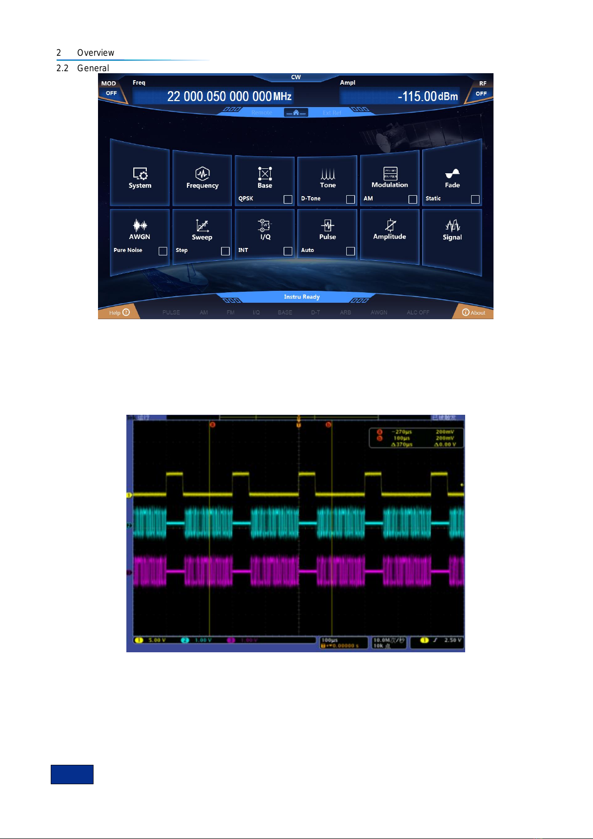
Fig. 2.11(a) Screenshot ofActual Operation Interface
2 Overview
2.2 General
10
Fig. 2.11(b) Screenshot of Actual Operation Interface
2) It supports flexible function configurations such as sweep, real-time baseband, etc.
The 1465 series signal generator supports flexible configurations such as sweep, real-time
baseband, and trigger source. The setting of trigger source determines the source of the event triggered,
and the setting of trigger mode determines the trigger action after event generation. Through the
combination of both, users can generate trigger signals according to actual needs of the test.
Fig. 2.12 Baseband Gating (Low Effective)
3) Abundant remote interfaces
There are multiple remote interfaces available for the 1465 series signal generator, including source
module port, GPIB port, network port, for easy remote control and network upgrading.
Other manuals for 1465 Series
2
This manual suits for next models
14
Table of contents
Popular Laboratory Equipment manuals by other brands


Sealey
Sealey SG18.V3 quick start guide

Linkam Scientific Instruments
Linkam Scientific Instruments FDCS196 user guide

Buchi
Buchi K-355 Operation manual

BASENHURT
BASENHURT Tebas-Economic EFka300 pH/Chlor Installation and maintenance instructions

laerdal
laerdal LCSU 4 user guide

overhoff
overhoff 357RM Operation & maintenance manual

Malvern
Malvern MicroCal iTC200 user guide

Fluigent
Fluigent FLOW UNIT user manual

Endress+Hauser
Endress+Hauser Liquiport 2010 CSP44 Brief operating instructions

Knauer
Knauer Azura Detector UVD 2.1S instructions

sterilAir
sterilAir T2018 Series operating manual

Applied Photophysics
Applied Photophysics Chirascan Integrating Sphere user manual