Ceyear 2438 Owner's manual

2438
Series Microwave Power Meter
Programming Manual
China Electronics Technology Instruments Co., Ltd

This manual is applicable to the following types of microwave power meters based on firmware version
1.0 and above.
2436 Series Microwave Power Meter
2348 Series Microwave Power Meter
Options:
English options: English menu, English panel, etc.
Version: A.1 November 2017, China Electronics Technology Instruments Co., Ltd (CETI)
Address: No.98, Xiangjiang Road, Qingdao City,China
Tel: +86-532-86896691
Website: www.ceyear.com
E-mail: sales@ceyear.com
Postal code: 266555

Foreword
Thank you for choosing the
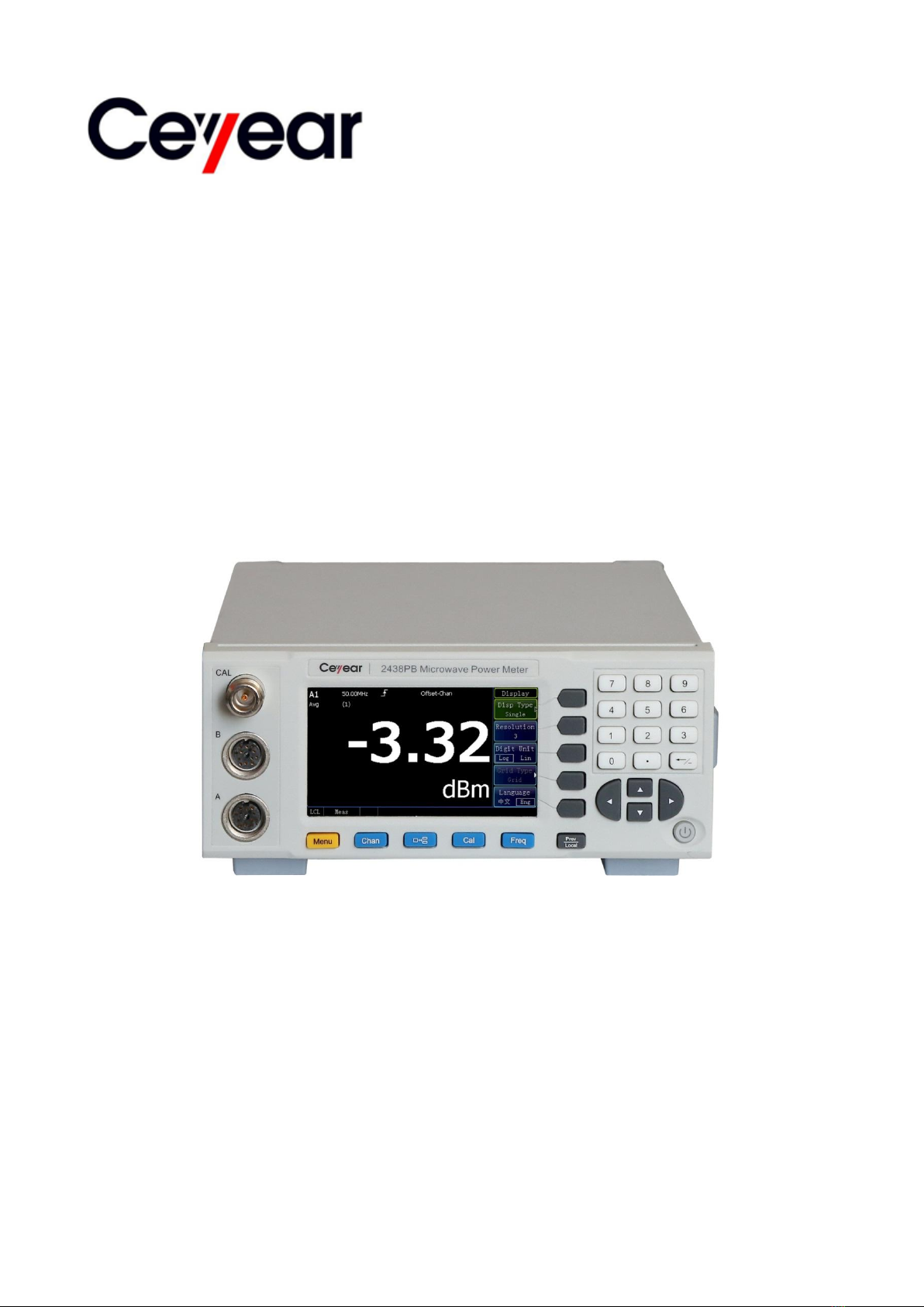
2348 series microwave power
meter developed and
manufactured by China
Electronics Technology
Instruments Co., Ltd. (CETI).
Our product is high-end,
precise and sophisticated, and
embraces a high cost
performance among the
competitors of the same class.
We are devoted to providing for
you high-quality products and
first-class after-sales service
with your most concerns and
demands in mind. Our
consistent aim is providing
excellent quality and good
service, and this is our sincere
commitment for all users.
Manual No.
AV2.715.1009/1010/1005/1006
SC
Version
A.1 2017.11
China Electronics Technology
Instruments Co., Ltd.
Manual Authorization
This manual may be subject to
change without notice. CETI
reserves all the rights to the
final explanation for all the
information and terminologies
referred to in this manual.
This manual is the property of
CETI. Without CETI's
permission, any organizations
or individuals shall neither
alter/temper nor
duplicate/transmit this manual
for profits; otherwise, CETI
reserves the right to pursue any
liabilities therefrom.
Product Warranty
The warranty period of this
product is 18 months from the
date of delivery. Instrument
manufacturer will repair or
replace the damaged parts
according to the user's
requirements and actual
situation in the warranty period.
The specific maintenance
matters should be subject to
the contract.
Product Quality
Certification
This product is certified to fulfill
the standards indicated in this
manual from the day of delivery.
Calibration measurements
have been carried out based on
national standards. Related
information is available to the
user for reference.
Quality/Environmental
Management
The quality and environmental
management systems have
always been implemented
during development,
manufacturing and test of this
product. China Electronics
Technology Instruments Co.,
Ltd. is properly qualified and
certified by ISO 9001 and ISO
14001 management system
standards.
Safety Precautions
CAUTION indicates an
important information rather
than danger. It reminds the
user to be cautious of a certain
operation process, operation
method or the similar. Failure to
follow the rules or operate
correctly may cause the
damage to the instrument or
loss of important data. The
conditions indicated by
CAUTION should be fully
understood and met before the
next operation.
NOTE indicates an information
prompt. It reminds the user to
pay attention to the instrument
or a certain operation process,
operation method or the similar,
so as to guide the instrument
operator to correctly use the
instrument.
CAUTION
NOTE


2438 Series Microwave Power Meter
Table of Contents
1
Table of Contents
1 About This Manual..................................................................................................1
1.1 About This Manual....................................................................................................................1
1.2 Related Documents...................................................................................................................1
2Remote Control.....................................................................................................3
2.1 Remote control basis................................................................................................................3
2.1.1 Remote interface........................................................................................................................... 3
2.1.2 Message.................................................................................................................................... 6
2.1.3 SCPI........................................................................................................................................... 7
2.1.4 Command sequence and synchronization......................................................................... 16
2.1.5 Status reporting system........................................................................................................ 18
2.1.6 Programming considerations ............................................................................................... 25
2.2 Remote interface and its configuration................................................................................26
2.2.1 LAN............................................................................................................................................... 26
2.2.2 GPIB.............................................................................................................................................. 27
2.3 I/O library..................................................................................................................................28
2.3.1 Overview of I/O library........................................................................................................... 28
2.3.2 Installation and configuration of I/O library......................................................................... 29
2.4 Zeroing and calibration of power sensor...............................................................................30
2.4.1 Zeroing.......................................................................................................................................... 30
2.4.2 Calibration............................................................................................................................... 30
2.4.3 Zero + calibration........................................................................................................................ 31
2.5 Measurement.............................................................................................................................31
2.6 Use of FDO table......................................................................................................................31
2.6.1 Overview ...................................................................................................................................... 31
2.6.2 Entering in FDO table................................................................................................................. 31
2.6.3 Selecting FDO table ................................................................................................................... 32
2.6.4 Enabling FDO table.................................................................................................................... 32
2.6.5 Measurement application .......................................................................................................... 32
2.6.6 Specific application..................................................................................................................... 32
2.7 Setting of display resolution....................................................................................................33
2.8 Setting of average ....................................................................................................................33
2.9 Setting of range.........................................................................................................................33

2348 Series Microwave Power Meter
Table of Contents
2
2.10 Setting of offset.......................................................................................................................33
2.10.1 Channel offset........................................................................................................................... 34
2.10.2 Display offset............................................................................................................................. 34
2.10.3 Specific application................................................................................................................... 34
2.11 Setting of measurement limit................................................................................................34
2.12 Status reporting.......................................................................................................................35
2.13 Save recall...............................................................................................................................35
3 SCPI ........................................................................................................................37
3.1 Command description..............................................................................................................37
3.2 Common command (IEEE488.2)...........................................................................................37
*CLS........................................................................................................................................................ 38
*DDT....................................................................................................................................................... 38
*ESE ....................................................................................................................................................... 39
*ESR?..................................................................................................................................................... 39
*IDN?...................................................................................................................................................... 39
*OPC....................................................................................................................................................... 40
*OPT?..................................................................................................................................................... 40
*RCL ....................................................................................................................................................... 40
*RST ....................................................................................................................................................... 40
*SAV ....................................................................................................................................................... 40
*SRE....................................................................................................................................................... 41
*STB? ..................................................................................................................................................... 41
*TRG....................................................................................................................................................... 42
*TST?...................................................................................................................................................... 42
*WAI........................................................................................................................................................ 42
3.3 Instrument subsystem command...........................................................................................42
3.3.1 Calculation (CALCulate) ......................................................................................................... 43
3.3.2 Calibration (CALibration) ........................................................................................................... 50
3.3.3 Measurement (CONFigure/FETCh/READ/MEASure)........................................................... 51
3.3.4 Display (DISPlay)........................................................................................................................ 64
3.3.5 Format (FORMat)........................................................................................................................ 66
3.3.6 Memory (MEMory/MMEMory)................................................................................................... 67
3.3.7 Output (OUTPut)......................................................................................................................... 71

2438 Series Microwave Power Meter
Table of Contents
3
3.3.8 Statistic (PSTatistic) ................................................................................................................... 74
3.3.9 Sense (SENSe)........................................................................................................................... 84
3.3.10 Status (STATus)....................................................................................................................... 98
3.3.11 System (SYSTem).................................................................................................................. 128
3.3.12 Trace (TRACe)........................................................................................................................ 162
3.3.15. Trigger (INITiate/TRIGger)................................................................................................... 166
3.3.16 Unit (UNIT)............................................................................................................................... 172
3.3.17 Service (SERVice).................................................................................................................. 173
4 Programming example .......................................................................................176
4.1 Basic operation example.......................................................................................................176
4.1.1 VISA library................................................................................................................................ 176
4.1.2 Example running environment................................................................................................ 176
4.1.3 Initialization and default status setting................................................................................... 177
4.1.4 Sending of setting command.............................................................................................. 178
4.1.5 Reading of instrument status ............................................................................................. 178
4.1.6 Synchronization of command............................................................................................. 179
4.2 Advanced operation example...............................................................................................180
4.2.1 Network remote control example............................................................................................ 180
4.2.2 GPIB remote control example................................................................................................. 184
5 Error Description..................................................................................................187
5.1 Error information.....................................................................................................................187
5.1.1 Local error information............................................................................................................. 187
5.1.2 Remote control error information............................................................................................ 187
5.2 Repair method.........................................................................................................................191
5.2.1 Contact us............................................................................................................................. 192
5.2.2 Packaging and delivery....................................................................................................... 192
Appendixes..............................................................................................................193
Appendix A Lookup Table of the SCPI by Subsystem.........................................................193


1 About This Manual
1.1 About This Manual
1
1 About This Manual
This chapter introduces the function, compositions and main content of the Programming Manual of the
2438 series microwave power meter as well as other related documents provided to the user.
About This Manual.......................................................................................................... 1
Related Documents......................................................................................................... 1
1.1 About This Manual
This manual introduces the remote control and the SCPI operation method of the 2438 series microwave
power meter, as well as the programming examples and the basic concept of the I/O function library to
facilitate the user to quickly master the programming method. To facilitate your familiarity with the
instrument, please read this manual carefully before operating the instrument, and then follow the
instructions of manual.
SCPI (Standard Commands for Programmable Instruments) defines standards and methods for remote
control of the instruments, and it is also the programming language for programmable instruments for
electronic test and measurement. The SCPI is based on the specifications and types in IEEE-488.2. For
details, please visit http://www.scpiconsortium.org.
This manual describes in detail the SCPIs of the 2438 series microwave power meter.
The chapters of the Programming Manual include:
Remote Control
This chapter introduces the remote control methods of the instrument so that the user can rapidly master
the method to control the instrument in a remote way. It is further divided into the following three sections:
remote control basis, which introduces the concepts related to remote control, software configuration,
remote interface, SCPI, etc.; instrument interface configuration method, which introduces the connection
method and software configuration method of the remote interface of the 2438 series microwave power
meter; the I/O function library, which introduces the basic concept of the instrument driver and the basic
installation and configuration of the IVI-COM/IVI-C driver.
SCPI
The common command, instrument command and compatibility command are introduced by category,
and functions, parameters, and examples of the SCPI are described one by one.
Programming Examples
The basic programming examples and advanced programming examples are given and described in the
form of explanatory note and example code, so as to facilitate the user to quickly master the
programming method of the microwave power meter.
Error Description
This chapter includes error information description and repair methods.
Appendixes
This chapter provides the necessary remote control reference information of the 2438 series microwave
power meter, including the SCPI lookup table.
1.2 Related Documents
The documents associated with the 2438 series microwave power meter include:
Quick Start Guide
User Manual
Programming Manual
Quick Start Guide
This manual introduces the settings of the instrument as well as the basic operating methods of

1 About This Manual
1.2 Related Documents
2
measurement with the aim of enabling users to quickly understand the features and operational
procedures of the instrument. Main chapters included in this manual are as follows::
Preparation before Use
Typical Applications
Getting Help
User Manual
This manual describes in detail the functions and operational protocols of the instrument, including
set-up, measurement, program control, maintenance, etc. so as to provide users with an all-round
understanding of the features of the instrument and aid users in learning the most common
measurement procedures. Main chapters included in this manual are as follows::
About This Manual
Overview
Start Guide
Operation Guide
Menu
Remote Control
Fault Diagnosis and Repair
Specifications and Test Methods
Appendixes
Programming Manual
This manual describes in detail the basics of remote programming, SCPI basics, SCPI, programming
examples, I/O driver library, etc. for the purpose of guiding the user to master the SCPIs and methods of
the instrument quickly and comprehensively. Main chapters included in this manual are as follows::
Remote Control
SCPI
Programming Examples
Error Description
Appendixes

2 Remote Control
2.1 Remote control basis
3
2 Remote Control
This chapter introduces the remote control basis as well as the remote interface and its configuration
method of the 2438 series microwave power meter, and also briefly describes the concept and
classification of the I/O driver library so that the user can have a preliminary knowledge about the remote
control of this instrument. The specific content includes:
Remote control basis.....................................................................................................3
Remote interface and its configuration........................................................................26
I/O library......................................................................................................................28
Zeroing and calibration of power sensor......................................................................30
Measurement...............................................................................................................31
Use of FDO table .........................................................................................................31
Setting of display resolution.........................................................................................33
Setting of average........................................................................................................33
Setting of range............................................................................................................33
Setting of offset............................................................................................................33
Setting of measurement limit .......................................................................................34
Status reporting............................................................................................................35
Save recall....................................................................................................................35
2.1 Remote control basis
Remote interface............................................................................................................3
Message.........................................................................................................................6
SCPI...............................................................................................................................7
Command sequence and synchronization ..................................................................16
Status reporting system...............................................................................................18
Programming considerations.......................................................................................25
2.1.1 Remote interface
LAN interface .................................................................................................................4
GPIB interface................................................................................................................6
RS-232 interface............................................................................................................6
USB interface.................................................................................................................6
The instrument with remote control functions generally supports two kinds of remote interfaces:LAN and
GPIB. The type of port supported by the instrument will be determined by its own functions.
The description of the remote interface and associated VISA addressing string is as shown in the
following table:

2 Remote Control
2.1 Remote control basis
4
Table2.1Type of the Remote Interface and VISAAddressing String
Remote Interface
VISAAddressing String
Description
LAN
(Local Area Network)
VXI-11 protocol:
TCPIP::host_address[::LAN_de
vice_name][::INSTR]
Raw socket protocol:
TCPIP::host_address::port::SO
CKET
Controller realizes remote control by
connecting the instrument via the
network port on the rear panel of the
instrument.
For the specific protocol, please refer
to:
2.1.1.1 LAN interface
GPIB
(IEC/IEEE Bus Interface)
GPIB::primary
address[::INSTR]
Controller realizes remote control by
connecting the instrument via the
port on the rear panel of the
instrument.
The IEC 625.1/IEEE 418 bus
interface standard is observed.
For details, please refer to:
2.1.1.2 GPIB interface
RS-232
(RecommendedStandard-232)
Instrument‟s rear panel port
For details, please refer to:
2.1.1.3 RS-232 interface
USB
(Universal Serial Bus)
USB::<vendor
ID>::<product_ID>::<serial_nu
mber>[::INSTR]
Instrument‟s rear panel port
For details, please refer to:
2.1.1.4 USB interface
2.1.1.1 LAN interface
The microwave power meter is available for remote control through the 10Base-T and 100Base-T LAN
computers. The instruments can be combined into a system within the LAN, and uniformly controlled by
the LAN computers. In order to realize the remote control within the LAN, the microwave power meter
shall be preinstalled with the port connector, network card and relevant network protocol, and configured
with relevant network service.And, the controller computer within the LAN shall also be preinstalled with
the instrument control software and VISAlibrary. The three working modes of the network card include:
10 Mbit/s Ethernet IEEE802.3;
100Mbit/s Ethernet IEEE802.3u;
1 Gbit/s Ethernet IEEE802.3ab.
The controller computer and the microwave power meter shall be connected with a common TCP/IP
protocol network through the network port. The cable between the computer and the microwave power
meter is a commercial RJ45 cable (shielded or unshielded CAT 5 twisted pair). During data transmission,
data packet transmission will be adopted, and LAN transmission is faster. Generally, the cable between
the computer and the microwave power meter shall not be longer than 100 m (100Base-T and
10Base-T). For more information about the LAN communication, please refer to: http://www.ieee.org.
The knowledge of LAN interface is introduced hereinafter.
1) IP address
When remote control of the microwave power meter is achieved through LAN, unblocked physical
connection of the network should be guaranteed. It can be completed by setting the address to the
subnetwork where the main control computer is located through the menu “Local IP” of the microwave
power meter. For example, if the IP address of the main control computer is 192.168.12.0, the IP
address of the microwave power meter shall be set to 192.168.12.XXX, and XXX is between 1 and 255.
Only the IP address is required to establish a network connection. The VISA addressing string is as
follows:

2 Remote Control
2.1 Remote control basis
5
TCPIP::host address[::LAN device name][::INSTR] or
TCPIP::host address::port::SOCKET
Where,
TCPIP - network protocol used;
host address - IP address or host name of the instrument, for identification and control of the
controlled instrument;
The LAN device name defines the handle number of the protocol and sub-device (optional);
—The VXI-11 protocol is adopted for the 0# device;
—The newer high speed LAN instrument protocol is adopted for the 0# high speed LAN instrument;
The INSTR represents the instrument resource type (optional);
The port represents the socket port number;
SOCKET - raw socket resource class.
Example:
The IP address of the instrument is 192.1.2.3, and the valid resource string of the VXI-11 protocol is:
TCPIP::192.1.2.3::INSTR
When the raw socket connection is created, the following addressing string can be used:
TCPIP::192.1.2.3::5000::SOCKET
Method for identification of multiple instruments in the remote control system
If multiple instruments are connected to the network, they can be identified by their individual IP address
and associated resource string. The main control computer uses the respective VISA resource string for
instrument identification.
2) VXI-11 protocol
The VXI-11 standard is based on the ONC RPC (Open Network Computing Remote Procedure Call)
protocol, which is the network/transport layer of the TCP/IP protocol. The TCP/IP network protocol and
relevant network service have been configured in advance. During communication, this
connection-oriented communication can follow a sequential exchange and identify the interruption of the
connection, thus ensuring no information loss.
3) Socket communication
The TCP/IP protocol connects the microwave power meter in the network through the LAN socket. As a
basic computer network programming method, the socket enables applications with different hardware
and operating systems to communicate in the network, which achieves two-way communication
between the microwave power meter and the computer through the port.
The socket is a special software class that defines the necessary information for network communication
such as IP address and device port number and integrates some basic network programming operations.
Sockets can be used in the operating system installed with a packaged library. UNIX Berkeley socket
and Winsock are commonly used.
Berkeley socket and Winsock are compatible in the microwave power meter through the application
program interface (API). In addition, other standard sockets are also compatible through the API. When
the microwave power timing is controlled by the SCPI, the socket program will give a command. Before
NOTE

2 Remote Control
2.1 Remote control basis
6
using the LAN socket, the socket port number of the microwave power meter shall be set in advance.
The socket port number of the microwave power meter is 5000.
2.1.1.2 GPIB interface
The GPIB interface is a widely-used instrument remote interface currently, which can be connected with
different kinds of instruments through the GPIB cable and can establish the test system with the main
control computer. To realize remote control, the main control computer shall be preinstalled with the
GPIB bus card, driver and VISA library. During communication, the main control computer will address
the controlled instrument through the GPIB bus address firstly. The user can set the GPIB address and
ID for querying strings, and the GPIB communication language can be set to the SCPI form by default.
The operation of the GPIB and its relevant interface is defined and described in details in theANSI/IEEE
standard 488.1-2003 and the ANSI/IEEE standard 488.2-1992. For details of the standard, please refer
to the IEEE website: http://www.ieee.org.
As the GPIB processes information in bytes and the data transmission rate can reach 8 MBps, the GPIB
data transmission is faster. As the data transmission speed is restricted by the distance between the
device/system and the computer, attention shall be paid to the followings during the GPIB connection:
Up to 15 instruments may be set up through the GPIB interface;
The total length of the transmission cable shall not exceed 15 m, or shall not exceed twice of
number of instruments in the system. Generally, the maximum length of the transmission cable
between the device shall not exceed 2 m;
If several instruments are connected in parallel, the “Or” connecting line shall be used;
The terminal of the IEC bus cable shall be connected with the instrument or the controller computer.
2.1.1.3 RS-232 interface
The RS-232 is a traditional remote control method.As only one bit of data is sent and received at a time,
the transmission rate is slower than that of the GPIB or the LAN, which is rarely used currently. Similar to
the GPIB and the LAN, the instrument parameters, such as baud rate, shall be set when establishing
communication, so as to match the parameters of the main control computer. The RS-232 transmits the
SCPI character in the form of the ASCII code.
2.1.1.4 USB interface
To achieve remote control through the USB interface, the computer and the microwave power meter
should be connected via a USB B-type interface, and the VISA library should be installed in advance.
VISA automatically tests and configures the instrument to establish a USB connection, without the
necessity of entry of the instrument address string or installation of an individual driver.
USB address:
Addressing string format: USB::<vendor ID>::<product ID>::<serial number>[::INSTR]
Where,
<vendor ID> ID of vendor;
<product ID> ID of instrument;
<serial number> Serial number of instrument.
Example:
USB::0x0AAD::0x00C6::100001::INSTR
0x0AAD: ID of vendor;
0xC6: ID of instrument;
100001: Serial number of instrument.
2.1.2 Message
Messages transmitted by data cable fall into the following two categories:

2 Remote Control
2.1 Remote control basis
7
1) Interface message
During communication between the instrument and the main control computer, it is necessary to pull
down the attention line and then the interface message can be transmitted to the instrument through the
data line. Only the instrument with the GPIB bus functions can send the interface message.
2) Device message
For the structure and syntax of device massage, refer to Section "2.1.3 SCPI". Device massage can be
divided into command and instrument response according to the different transmission directions. All
remote control interfaces use device massage in the same method unless otherwise status.
a) Commands:
A command (program message) is a message transmitted from the main control computer to the
instrument for remote control of instrument functions and query of status information. It falls into the
following two categories:
Based on the impact on the instrument:
- Setting command: Change the instrument setting status, e.g. reset the instrument or set the frequency.
- Query command: Query and return the data, e.g. identify the instrument or query the parameter values.
The query command is always ended with a question mark.
Based on the definition in the standard:
- Common commands: Functions and syntax defined by IEEE488.2 for all types of instruments (if
implemented)
Used to implement: manage standard status registers, resets and self-tests.
- Instrument control command: Instrument-specific command, for realization of instrument functions. For
example: set the frequency.
The syntax also follows SCPI specification.
b) Instrument response:
The instrument response (response message and service request) is the query result information sent
by the instrument to the computer. This information includes measurement result and instrument status.
2.1.3 SCPI
Brief introduction to SCPI...............................................................................................7
Instructions of SCPI .......................................................................................................8
2.1.3.1 Brief introduction to SCPI
SCPI (Standard Commands for Programmable Instruments) is a set of commands established for all
instruments based on IEEE488.2 mainly to achieve the universality of SCPI, i.e. the same SCPI is
generated and issued for the same function.
The SCPI consists of a command header and one or more parameters which are separated by a space.
The command header contains one or more key fields. The command with question mark as postfix is a
query command. Commands are divided into common commands and instrument-specific commands
that are different in syntactic structure. SCPI has the following features:
1) The SCPI is established for the test functions rather than instrument operation description.
2) The SCPI reduces the repetition of the realization process of similar test functions, thus ensuring the
programming compatibility;
3) The program message is defined in a sub-layer irrelated with hardware of the communication
physical layer;

2 Remote Control
2.1 Remote control basis
8
4) The SCPI is irrelated with the programming methods and languages, and the SCPI test program is
easy to be transplanted;
5) The SCPI has scalability, and can adapt to control of different scales of measurement;
6) Scalability makes SCPI a “Live” standard.
If you are interested in learning more about SCPI, please refer to:
IEEE Standard 488.1-2003, IEEE Standard Digital Interface for Programmable Instrumentation.
New York, NY, 1998.
IEEE Standard 488.2-1992, IEEE Standard Codes, Formats, Protocols and Comment Commands
for Use with ANSI/IEEE Std488.1-2003. New York, NY, 1998
Standard Commands for Programmable Instruments(SCPI) VERSION 1999.0.
For details about the SCPI set, classification and description of the 2438 series microwave power
meter , please refer to:
1) “3 SCPI” of this manual;
2) “Appendix A Lookup Table of the SCPI by Subsystem” of this manual.
2.1.3.2 SCPI description
General terms ................................................................................................................8
Command type...............................................................................................................9
Instrument-specific command syntax ............................................................................9
Command tree .............................................................................................................12
Command parameter and response............................................................................13
Systems of Values in Commands................................................................................16
Command line structure...............................................................................................16
1) General terms
For the purpose of this section, the following terms should apply. It is necessary to know about the exact
definitions of these terms for a better understanding of the content in various chapters.
Controller
The controller is any computer used to communicate with the SCPI device. The controller may be a
personal computer, a small computer or a card inserted onto a cage. Some artificial intelligence device
can also be used as a controller.
Device
The device is any component that supports SCPI. Most devices are electronic measuring or excitation
device and use the GPIB interface for communication.
Program message
The program message is a combination of one or more correctly formatted SCPIs. It guides the device to
measure and output the signal.
Response message
The response message is a data set that specifies the SCPI format. It is always sent from the device to
the controller or listener to remind the controller of the internal condition or measured value of the device.
Command
A command is an instruction in compliance with the SCPI standard. The combination of controller
commands forms a message. In general, a command includes the keyword, parameter and punctuation.
Event command

2 Remote Control
2.1 Remote control basis
9
An event-type SCPI can't be queried. An event command generally has no corresponding key settings
on front panel. Its function is to trigger an event at a particular moment.
Query
Query is a special command. When the controller is queried, it is necessary to return to the response
message in conformity with syntax requirement of the controller. The query statusment is always ended
with a question mark.
2) Command type
There are two types of SCPIs: common commands and instrument-specific commands. Figure 2.1
shows the difference between two commands. Common commands are defined in IEEE 488.2 to
manage macros, status registers, synchronization, and data storage. As the common command begins
with a *, it can be easily distinguished. For example *IDN? , *OPC and *RST are common commands.
Common commands don‟t belong to any instrument-specific command. The instrument uses the same
method to interpret them without consideration to the current path setting.
It is very easy to identify instrument-specific commands because they contain a colon (:). The colon is
used between the beginning of a command expression and a keyword, for example: FREQuency[:CW?].
Instrument-specific commands are divided into command subsets of corresponding subsystem
according to the functional block inside the instrument. For example, the power subsystem (:POWer)
contains the power-related command while the status subsystem (:Status) contains the command for the
status control register.
Fig.2.1 SCPI type
3) Instrument-specific command syntax
A typical command consists of keywords with colon as prefix.. These keywords are followed by
parameters. An example of syntax statusment is shown below.
[:SENSe]:FREQuency[:CW|FIXed] MAXimum|MINimum
In the above example, the [:CW|FIXed] part of the command is closely followed by :FREQuency, and
there is no space in the middle. The part closely following the [:LEVel]: The MINimum|MAXimum is the
parameter part. There is a space between the command and the parameter. The description of other
parts of the syntax expression is as shown in Table 2.2 and Table 2.3.
SCPI
Common
co
Subsystem
comm
*IDN?
*RST
:SYSTem:PRESet:TYPE?
:FREQ 1kHz

2 Remote Control
2.1 Remote control basis
10
Table2.2 Special Characters in the Command Syntax
Symbol
Meaning
Example
|
The vertical line between the keyword and the
parameter represents a variety of options.
[:SENSe]:BANDwidth|BWIDth
HIGH|LOWer
BANDwidth and BWIDth are
options,
and HIGH and LOWer are options.
[]
Square brackets indicate that the included keywords or
parameters are optional
when they form a command. These implied keywords
or parameters are executed
even when they are ignored.
[:SENSe]:BANDwidth?
SENSe is optional.
< >
The part inside the angle brackets can't be used literally
in the command, instead, it represents the part that
must be contained.
[:SENSe]:FREQency[:CW|FIXed]
<val>[unit]
In this command, <val>
must be replaced by the actual
frequency.
[unit] means a unit that can be
omitted.
For example: FREQ 3.5GHz
FREQ 3.5e+009
{ }
The part inside the braces indicates that the parameter
is optional.
MEMory:TABLe:FREQuency
<val>{,<val>}
For example: MEM:TABL:FREQ
5e7
Table2.3 Command Syntax
Character, Keyword and Syntax
Example
Capitalized characters represent the minimum character set
required to execute the command.
[:SENSe]:FREQuency[:CW|FIXed]?,
FREQ is the short-format part of the
command.
The lowercase character part of the command is optional; this
flexible format is called “Flexible Listening”. For more
information, please refer to the section “Command parameter
and response”.
:FREQuency
:FREQ, :FREQuency or
:FREQUENCY,
any of which is correct.
A colon between two command mnemonics moves the current
path in the command tree downwards by one layer. For more
information, please refer to the command path part in the
section “Command tree”.
:TRIGger:MODE?
TRIGger is the topmost keyword of this
command.
If the command contains multiple parameters, the adjacent
parameters will be separated by commas. The parameter isn't
a part of the command path, so it doesn't affect the path layer.
MEMory:TABLe:FREQuency
<val>{,<val>}
The semicolon separates two adjacent commands but doesn't
affect the current command path.
:FREQ 2.5GHZ;:POW 10DBM
Blank characters such as <space> or <tab> are usually
ignored as long as they don't appear between the keywords or
in the keyword. However, the command and parameter must
be separated by a blank character, without affecting the
current path.
:FREQ uency or :POWer :LEVel6.2 is
not allowed.
:LEVel and 6.2 must be separated by a
space.

2 Remote Control
2.1 Remote control basis
11
i.e. :POWer:LEVel 6.2
The simplified syntax specification is as shown in Figure 2.2:
Fig.2.2 SCPI type
For example, the syntax expression of “[:SENSe[1]|2]:FREQuency[:CW|FIXed] <Numeric Data>” can be
expressed as follows.
Fig.2.3 SCPI type
Remarks:
1) The space can‟t be added in the above Figure unless otherwise indicated. There can be one or
more spaces. If the unit is omitted, the standard unit of frequency and time is Hz and s respectively.
2) The rounded rectangle represents the actual characters required for a keyword or a command, such
as “:”, “,”, “?”, “1”; the right-angle rectangle represents that it shall be replaced with actual characters,
numbers, etc. If the “Value” can‟t appear in the command, it shall be replaced with the actual value,
such as 5e+007.
3) Regardless of the length format of the keyword, set the frequency of channel A to 50 MHz. The
following several forms are displayed in the above Figure (only the short format of the keyword is
taken. As there are a number of units of frequency, such as Hz, kHz, MHz, GHz, THz, they will not
be given in details due to length limitations. It is only necessary to replace 5.0e+007 with
corresponding units, such as 50 MHz, 5e+007 Hz, 0.05 GHz).
a) :SENS1:FREQ:CW 5.0e+007 No keyword will be omitted
b) SENS1:FREQ:CW 5.0e+007 The “:” in front of the SENS1 will be omitted.
c) SENS:FREQ:CW 5.0e+007 The “1” will be omitted.
d) FREQ:CW 5.0e+007 The SENS will be omitted.
e) :SENS1:FREQ:FIX 5.0e+007 No keyword will be omitted
f) SENS1:FREQ:FIX 5.0e+007 The “:” in front of the SENS1 will be omitted.
g) SENS:FREQ:FIX 5.0e+007 The “1” will be omitted.
h) FREQ:FIX 5.0e+007 The SENS will be omitted.
i) :SENS1:FREQ 5.0e+007 The CW or the FIX will be omitted
j) SENS1:FREQ 5.0e+007 The “:” and CW or FIX in front of the SENS1 will be
omitted.
Keyword
Space
Parameter
Suffix
?
:
,
:
SENS
:
1
:
SENS2
SENS8
FREQ
:CW
:FIX
Value
Space
Unit
DEF
MIN
MAX
?
Space
MAX
MIN

2 Remote Control
2.1 Remote control basis
12
k) SENS:FREQ 5.0e+007 The “1” and CW or FIX will be omitted.
l) FREQ 5.0e+007 The SENS and CW or FIX will be omitted.
4) For the frequency of channel B and channel 8, the SENS2 and the SENS8 can‟t be omitted.
5) The MIN and the MAX can be used as parameters to set the command or to query the command.
The DEF can only be used as a parameter to set the command. The specific values of the MIN,
MAX and DEF are related to the instrument. In this case, the frequency range of channel A and
channel B is the same. The minimum, maximum and default frequencies are 1 kHz, 1 THz and 1
GHz respectively, and the value of the USB channel is 1 kHz, 1 THz and 50 MHz accordingly.
a) FREQ DEF Set the frequency of channelA to the default value.
b) FREQ? MAX Query the maximum settable frequency of channel A, and a
value without units is returned.
6) If consideration is given to the length form of the keyword but no consideration is given to the
command with units, the command in the above Figure will have 1,632 forms totally. The user is
unnecessary to care about all the forms, flexible use is enough. The following is a simple calculation,
and the interested users can make calculation on themselves.
a) Firstly, calculate the default condition of the SENS, and record it as N1.
The FREQ/FREQuency has 2 forms, which is recorded as N11.
The CW/FIX/FIXed/omission has 4 forms, which is recorded as N12.
The parameters to set the command have 7 types, including
value/DEF/DEFault/MIN/MINimum/MAX/MAXimum.
The parameters to query the command have 5 types, including
MIN/MINimum/MAX/MAXimum/omission, namely, there are 12 parameter forms, which is
recorded as N13, and
9612421312111
NNNN
b) After that, calculate the non-default condition of the SENS, and record it as N2.
The first “:” has omission and no-omission types, which is recorded as N21.
The SENS/SENSe has 2 types. The affix has 4 types including 1/2/6/omission, namely, the
SENS keyword has 2×4 types, 8 types totally, which is recorded as N22.
The SENS keyword and the following keyword form a combination relationship,
11618222212
NNNNN
c) Including N types of forms totally, and
163211721
NNNN
4) Command tree
Most remote control programming tasks involve instrument-specific commands. When such a command
is parsed, the SCPI will use a structure similar to the file structure, and it is called as a command tree, as
shown in Figure 2.4:
Fig.2.4 Schematic Diagram of the Simplified Command Tree
The top command is root command, or simply “root”. In the case of command parsing, the command at
the next layer is reached by following a specific route based on the tree structure. For
example::POWer:ALC:SOURce?, where, POWer stands for AA,: ALC stands for BB, :SOURce stands
for GG, and the whole command path is (:AA:BB:GG).
AA
BB
CC
DD
EE
FF
GG
HH
JJ
Root
First l
Secondl
II
Table of contents
Other Ceyear Measuring Instrument manuals

Ceyear
Ceyear 3672 Series User manual

Ceyear
Ceyear 4024 Series User manual

Ceyear
Ceyear 3986 Series Owner's manual

Ceyear
Ceyear 87234 Series User manual

Ceyear
Ceyear 4041 Series User manual

Ceyear
Ceyear 3986 Series User manual

Ceyear
Ceyear 3656 Series User manual

Ceyear
Ceyear 4024 Series User manual

Ceyear
Ceyear 4957D User manual

Ceyear
Ceyear 4024 Series User manual