Ceyear 4957D User manual

4957D/E/F
Microwave Analyzer
Quick Start Guide
China Electronics Technology Instruments Co., Ltd.


Foreword
Thank you for choosing and
using 4957D/E/F microwave
Analyzers developed and
produced by China Electronics
Technology Instruments Co., Ltd!
Manual No.
AV2.732.1020SK
Version
A.1 2018.9
China Electronics Technology
Instruments Co., Ltd.
Manual Authorization
The contents of this manual are
subject to change without notice.
The final right to interpret the
contents and terms used in this
manual belongs to China
Electronics Technology
Instruments Co., Ltd.
CETI holds the copyright of this
manual. No organization or
individual is allowed to modify or
alter the contents herein or copy
or distribute this manual for the
purpose of profit without the
authorization of the company.
CETI reserves the right to
pursue legal liability for the
infringers.
Product Warranty
We will repair or replace the
damaged components as
required within the warranty
period. For this purpose, the
user shall return the product to
the manufacturer and prepay the
mailing fee.
Product Quality certificate
We guarantee that the product
can meet the indicator
requirement in the manual upon
delivery. The calibration and
measurement are completed by
measuring bodies with national
qualification, with relevant data
to be provided for reference by
users.
Quality / Environment
Management
This product complies with the
quality and environmental
management systems during
R&D, manufacturing and testing.
China Electronics Technology
Instruments Co., Ltd has passed
the certification of ISO 9001 and
ISO 14001 systems.
Safety precautions
The warning sign indicates a
potential risk. It reminds the user
of certain operation process,
operation method or similar
situation. In case of any failure
of observing the rule or
maloperation, personal injury
can occur. Proceed to the next
step only after fully
understanding and meeting the
warning conditions indicated.
Note mark, indicating some
important information which will
not cause danger. It reminds the
user of certain operation process,
operation method or similar
situation. In case of any failure
of observing the rule or
maloperation, instrument
damage or important data loss
can occur. Proceed to the next
step only after fully
understanding and meeting the
caution conditions indicated.
Warning
Note

Contents
Chapter I Manual Navigation ................................................................................1
Chapter II Getting Prepared..................................................................................2
2.1 Preparation before operation................................................................................2
2.2 Power-on...................................................................................................................4
2.3 Front Panel ...............................................................................................................4
2.4 Operator Interface...................................................................................................6
2.5 Top Interfaces ..........................................................................................................6
2.6 Battery........................................................................................................................8
Chapter III Typical Applications.............................................................................9
3.1 Calibration in the VNA Mode.................................................................................9
3.2 DTF Measurement in the CAT Mode................................................................15
3.3 Signal Measurement in the SA Mode...............................................................16
3.4 Measuring Signal Power in the Power Monitor (PM) Mode.........................18
3.5 Measuring the Electrical Length of Cables or Other DUTs in the
VVM Mode.....................................................................................................................19
3.6 Measuring Average Power in the UBS-PM Mode..........................................21
3.7 TestingSkills............................................................................................................23
Chapter IV Getting Help......................................................................................26
4.1 Basic Inspection.....................................................................................................26
4.2 Help information.....................................................................................................26
4.3 Repair.......................................................................................................................27
Annex 1: Technical indicators.............................................................................28
Annex 2: List of Accessories / Options................................................................30

4957D/E/F Microwave Analyzer Quick Start Guide
1
Chapter I Manual Navigation
This manual introduces the structure and use of 4957D/E/F microwave analyzer
(hereinafter referred to as 4957D/E/F or analyzer) from such aspects as instrument panel,
power supply, startup, typical applications and obtaining after-sales support. By reading
this manual, we can have a relatively systematic overall understanding of 4957D/E/F,
and can quickly master some basic operations of the analyzer. To facilitate your skillful
use of such instrument, please read carefully and follow this manual in advance for
correct operation.
The Quick Start Guide of 4957D/E/F Microwave Analyzer contains the following chapters
and sections:
Get Prepared
This chapter introduces the preparation before operation, startup, panel introduction
and battery replacement of 4957D/E/F. After reading this chapter, you can have a
perceptual knowledge of 4957E/E/F as a whole, and make early preparation for
correct and safe operation of the instrument.
Typical Applications
This chapter introduces the calibration of 4957D/E/F in detail and, through DTF test
and other test examples, details the operation steps for the basic measurement
format of 4957D/E/F, and briefly introduces the skills used in the tests. After reading
this chapter, you can independently use 4957D/E/F to complete the testing of some
typical tested pieces.
Get Help
This chapter includes two parts: After-sales maintenance and repair, with a focus on
troubleshooting, maintenance and repair of the instrument during use.

4957D/E/F Microwave Analyzer Quick Start Guide
2
Chapter II Getting Prepared
The 4957D/E/F microwave analyzers are exquisitely designed and comfortable to
operate. They are small in size, with the maximum external dimensions (width ×height ×
depth) of only 315 mm ×220 mm ×102 mm (excluding handles, footpads and supports);
light, with the total weight of not more than 5.3 kg for each unit (excluding rechargeable li-
ion batteries). Therefore, they are easily carried for field tests. This chapter will focus on
the test environment, power supply, structure and battery replacement of the instrument.
2.1 Preparation before operation
This section introduces the precautions before first use of a 4957D/E/F microwave
analyzer. 4957D/E/F meets the safety requirements specified in GJB3947A-2009. Please
read the following safety instructions carefully so as not to cause damage to the
instrument or unnecessary personal injury.
To prevent the instrument from damages and to avoid electric
shock, fire and personal injury:
Do not open the cabinet without permission;
Do not try to disassemble or refit any part of the instrument not
mentioned in the manual. Otherwise, such consequences as
reduced electromagnetic shielding property and internal component
damage can occur, affecting product reliability. In this case, we will
not provide any free maintenance any more even if the product is
still in the warranty period.
2.1.1 Environmental Requirements
In order to ensure the service life of 4957D/E/F and the validity and accuracy of
measurement, please carry out the tests under the following environmental conditions:
1. Temperature range:
Storage temperature range: -40~ +70
Working temperature range: -10~ +50
2. Low air pressure:
Low air pressure (altitude): 0 ~ 4,600 m
2.1.2 Power Supply Requirements
4957D/E/F can be powered in three ways:
1. AC power supply and adapter
When adopting AC power supply, the enclosed AC-DC adapter must be used. With the
input of 220 V / 50 Hz AC, the adapter is connected with a standard three-core power
cord. Pay attention to ensure proper grounding.
Since the working temperature range of the battery equipped with
the instrument is-20~ 60, the instrument should not work
continuously for a long time when it is equipped with the battery at
high temperature, so as to avoid danger caused by too high internal
temperature. It is recommended to use an adapter for power
supply.
Warning
Warning

4957D/E/F Microwave Analyzer Quick Start Guide
3
To avoid overheating, please do not connect the AC-DC adapter to the analyzer when
transporting or carrying it with a backpack. The voltage input range of the AC-DC adapter
is wide. Please ensure that the power supply voltage is within the range required in Table
2.1.
Table 2.1 power supply requirements
Power supply parameter
Applications
Input voltage
Rated input current
Working frequency
Output voltage / current
100 V 240 VAC
≥1.7 A
50 / 60 Hz
15.0 V / 4.0 A
The operating voltage and frequency ranges should be subject to
the data on the nameplate of the power adapter.
2. DC power supply
Voltage: 13 V ~ 17 V (without batteries), 15 V ~ 17 V (with batteries)
Current: 4 A (min.)
3. Built-in battery power supply
4957D/E/F can be powered by rechargeable li-ion batteries. If the battery is left unused
for a long time, it will be discharged by itself, so it must be charged before being used
again. See section 2.6 for details of battery usage. The basic parameters of the enclosed
battery are as follows:
Nominal voltage: 10.8 V
Nominal capacity: 7,800 mAh
Working time: About 2.5 h
Charging time: About 6 h
Rechargeable batteries should not be exposed to fire and high
temperature (higher than 60), thrown into fresh water or salt
water or wetted, and should be kept away from children.
Rechargeable batteries can be reused and should be placed in
suitable containers to avoid short-circuit. Heavy metals such as
nickel and chromium in batteries will pollute the natural
environment. Waste batteries should not be discarded casually, but
should be put into a special battery recovery bins.
2.1.3 Electrostatic Discharge (ESD) Protection
Attention should be paid to ESD protection when using the instrument. The following ESD
protection measures, if applicable, can be taken:
1. Before connecting the cable to the instrument for testing, make sure that the center
conductor of the cable is grounded first. This can be achieved in the following steps:
Connect a shorting device to one end of the cable to short-circuit the center conductor
and the outer conductor of the cable. When wearing antistatic wrist straps, grasp the
Note
Note

4957D/E/F Microwave Analyzer Quick Start Guide
4
housing of the cable connector, connect the other end of the cable, and then remove the
shorting device.
2. Perform grounding to yourself before cleaning, connecting or inspecting the test port of
the instrument. This can be achieved by grasping the grounded metal housing of the
instrument or the housing of the test cable connector.
2.2 Power-on
Before powering up 4957D/E/F, please check the power supply equipment according to
"Power supply requirements" in section 2.1.2. The power-on test can only be performed
after everything is confirmed to be correct.
Press and hold the Power On / Off key ([ ] key) for about three seconds, after hearing a
"beep", release the key, and the analyzer will take about 15 seconds to enter the self-
check program. In order to stabilize the performance indicators of the internal devices of
the instrument and achieve better test effect, it is recommended to preheat the instrument
for 20 ~ 30 min before measurement.
In this guide, the keys on the front panel are represented by [XXX],
with XXX being the key name; The keys on the bottom of the touch
screen are represented by [XXX], with XXX being the name of the
key; The menu keys on the right are represented by [XXX], with XXX
being the menu name.
2.3 Front Panel
This section details the front panel of 4957D/E/F, which is shown in Figure 2.1.
Figure 2.1 Front panel of 4957D/E/F microwave analyzer
The functions of common keys are described as follows:
[Freq]: In the Cable and Antenna Test (CAT) mode, Network Analyzer mode,
Spectrum Analyzer mode and Power Monitor mode, it is used to set such
measurement parameters as center frequency, start and stop frequencies, sweep
and frequency step. In USB Power Meter mode and Vector Voltmeter, it is used to
set the center frequency.
[Amp]: It is used to set such parameters as Auto Scale, Ref Level, Ref Pos, Scale
and Power in the CAT mode and Network Analyzer mode. In the Spectrum Analyzer
mode, it is used to set the amplitude parameters for displaying measurement results,
including setting reference level, attenuator, display scale, unit and preamplifier
control, etc.. In Power Monitor mode and USB Power Meter mode, it is used to set
d
e
f
g
8.4’’Touch
screen
Rotary knob
Power key and
indicator
Backspace, Cancel
and OK keys
Numeric input zone
Function
key zone
Reset key
Side strap
Step key
Speaker
Battery compartment
Note

4957D/E/F Microwave Analyzer Quick Start Guide
5
parameters such as reference, scale, max and min values, relative measurement
switch state, offset, etc.. In the Power Monitor mode, it can also turns on / off the
preamplifier.
[BW]: It is used to set such parameters as Average, Smooth and MF BW, etc., in the
CAT mode and the Network Analyzer mode. In the Spectrum Analyzer mode and the
Power Monitor, it is used to set RBW, VBW, Detector and Average, etc..
[Mkr]: In the CAT mode and Network Analyzer mode, it is used to open function
menus related to markers, including marker switching, opening and closing, Mkr
Peak Search, Delta Mkr and marker function settings. In the Spectrum Analyzer
mode, it is used to open function menus related to markers, including marker
switching, opening and closing, Mkr Peak Search, Delta Mkr, Counter and Noise Mkr
settings.
Measure: In the CAT mode, it is used to select the data format of measurement,
including VSWR, Return Loss, Impedance, Cable Loss, DTF VSWR and
DTF@Return Loss. In the Network Analyzer mode, it is used to select the required S
parameter measurement mode, data format and time domain function settings. In the
Spectrum Analysis mode, it is used to select different measurement functions,
including field strength measurement, channel power, OBW, AM / FM DM, ACPR, etc.
or set signal source power output. In the Vector Voltmeter mode, it is used to set
such parameters as measurement type, port selection, measurement format, relative
measurement switch and output power, etc..
[Mode]: It is used to select the working mode of the analyzer, which can be selected
as CAT, Network Analyzer, Spectrum Analyzer, Power Monitor, USB Power Meter
and Voltage Voltmeter, etc..
[Cal]: It is used to select the type of device under calibration piece, perform
calibration, turn calibration on and off, and resume calibration in the CAT mode,
NetworkAnalyzer mode, and Vector Voltmeter mode.
[Trace]: It is used to set such parameters as trace calculation and limit line in the
CAT mode and the Network Analyzer mode. In the Spectrum Analyzer mode, it is
used for switching, opening, closing, holding and refreshing traces and setting limit
lines, etc..
[Sweep]: It is used to set such parameters as Swp Time, Points, Swp mode and
Trigger mode in the CAT mode and the Network Analyzer mode. In the Spectrum
Analyzer mode, it is used to set such parameters as Swp Time, Swp Type and Swp
Mode, etc.. In the Power Monitor mode, it is used to set Swp Type.
[System]: In the local working mode, it is used for system date, time and power
saving mode, viewing electronic serial numbers of products, selecting system
operation language and other system-related settings; When the analyzer is under
remote control, press this key to restore local functions.
[File]: It is used for setting the working state of the analyzer as well as storing and
calling measurement data.
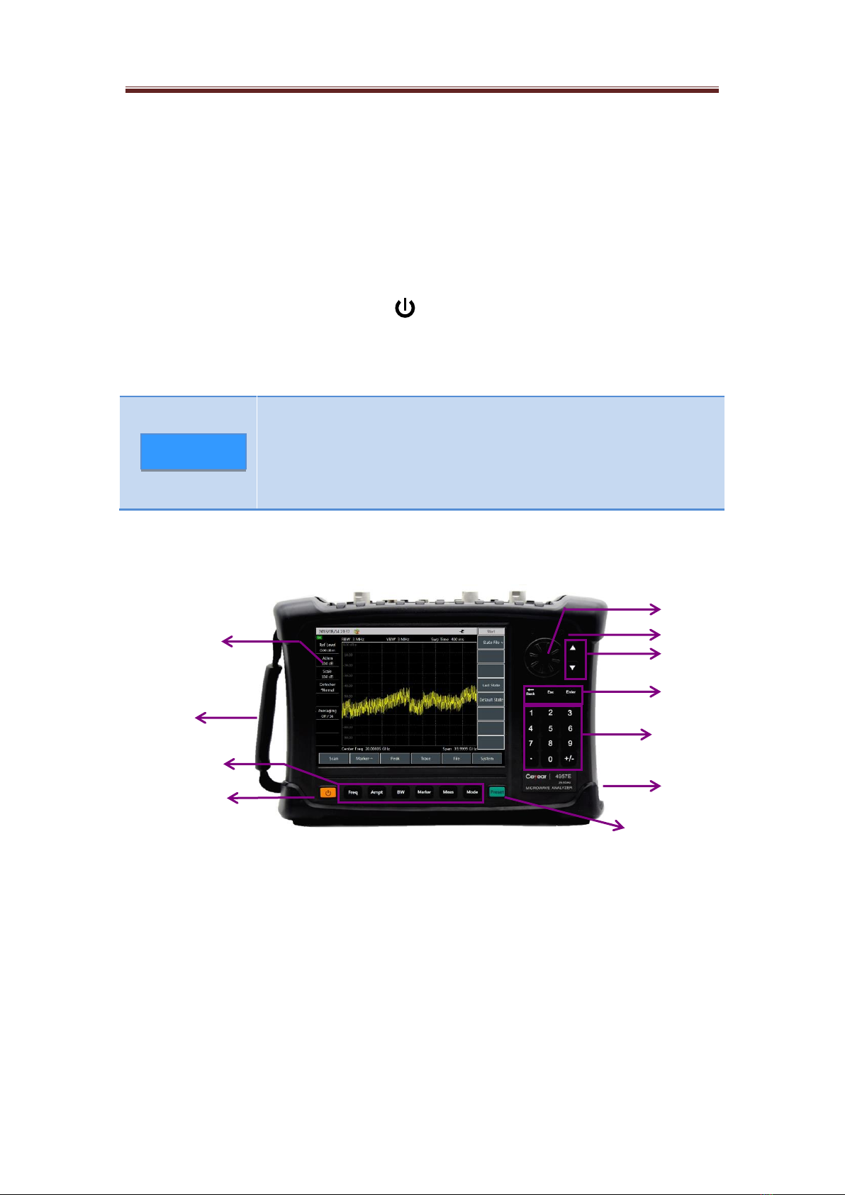
[↑] and [↓]: Are used to control stepping up and down or to move up and down to
select the current item.
[←] Backspace key: Is used to delete the last number or character entered.
[Cancel]: Is used to ignore the settings and input in the dialog box and close the
dialog box.
[OK]: Is used to confirm the settings and input values in the dialog box and close the
dialog box.
[Reset]: Is used for system reset, system restart and restoring to the default initial
state. Press this key and release it to reset.

4957D/E/F Microwave Analyzer Quick Start Guide
6
[ ]: Is used for turning on and off the analyzer. If an external power adapter is used
for power supply, when the instrument is in the "standby" state, the yellow indicator
near the power switch is on; Press and hold the power switch for over 3 seconds,
and the green indicator will be on, indicating that the instrument is in the "working"
state. Its colors corresponding to the physical states of the instrument are as shown
in the following table.
Table 2.2 Indicators states
Instrument state
Indicator state
Physical state of spectrum analyzer
Power off
Off
a) Battery installed, power not connected.
b) Battery not installed, power not connected.
Normal on, yellow
a) Battery not installed, power connected.
b) Battery installed and full, power connected.
Flashing, yellow
a) Battery installed and not full, power connected.
Power on
Normal on, green
a) Battery not installed, power connected.
b) Battery installed and full, power connected.
c) Battery installed, power not connected.
Flashing, green
a) Battery installed and not full, power connected.
Speaker: Please keep the opening clean, so as to guarantee the sound effect.
2.4 Operator Interface
4957D/E/F is equipped with a 8.4” touch screen LCD, which can offer good visibility
under direct sunshine. The operation interface is shown in Figure 2.2. Adhering to the
concept of energy conservation and environmental protection, 4957D/E/F also features
the sleep and automatic shutdown functions.
Figure 2.2 Operation interface of 4957D/E/F microwave analyzer
2.5 Top Interfaces
System status
bar
Submenu
zone
Main menu
zone
Main display
zone
Left info
display zone

4957D/E/F Microwave Analyzer Quick Start Guide
7
LAN Interface
Mini USB
Network port 1
Network port 2
Spectrum input
port
GPS antenna interface
Trig In interface
10 MHz in / out port
Earphone jack
SD card slot
Power interface
USB A port
The top panel of the 4957D/E/F can be divided into three parts: Power interface, digital
interfaces and test ports.
Figure 2.3 Top interfaces of 4957D/E/F microwave analyzer
2.5.1 Power Interface
The power supply interface of the instrument can supply power to the analyzer through
DC output of a AC-DC adapter or external DC power supply. The inner conductor of the
external power interface is positive, and the outer conductor is grounded.
2.5.2 Test Ports
1. GPS antenna interface: Marked as "GPS antenna", BNC (female), is used to connect
GPS antenna, with the internal GPS receiving module providing GPS functions.
2. Trig In interface: Marked as "Trig In", is used for external trigger signals and is a
3.5mm female port.
3. 10 MHz input / output port: Marked as "10 MHz In / Out", with 50 Ω impedance, BNC
female adapter. 4957D/E/F microwave analyzers can receive externally input 10 MHz
sine signals as phase-locked reference signals, and the input signals should meet the
frequency of 10 MHz + 100 Hz and the amplitude of 0 dBm (limited range:-20 DBM + 10
DBM); It can also output a sine signal of 10 MHz as the frequency reference signal of an
external device.
4. Spectrum input port: Marked as "SA RF In", is used for input of measured signals in
the Spectrum Analyzer mode. The test signal input port of 4957D/E/F microwave
analyzers is 50 Ω, N-type female or 3.5 mm or 2.4 mm male port.
5. Network test port: The test ports in the Network Test mode of the analyzer are two 50
Ω, N-type female or 3.5 mm or 2.4 mm male ports, respectively marked “Port 1” and “Port
2”, which can be switched between the RF source and the receiver to measure the in two
directions.
In order to better protect the analyzer, the test port of the
instrument is provided with some symbols. When using the
analyzer, users must pay attention to the symbols, so as to avoid
permanent damage to the instrument.
See section 2.5.4 for the description of the symbols of the
instrument.
Warning

4957D/E/F Microwave Analyzer Quick Start Guide
8
2.5.3 Communication Interfaces
1. Mini USB interface: Is used to connect the main equipment. If connected to an external
computer, the PC can run relevant tool software for programming and data transmission
of 4957D/E/F.
2. LAN (Network) Interface: Standard RJ-45 type, a 10 / 100 Mbps Ethernet connector
with a standard 8-pin structure that allows for automatic selection between two data rates.
It is used to connect to a local network or to realize remote control of the instrument.
3. Type A USB interfaces: 2, for connecting slave devices, such as USB storage devices,
a mouse or a keyboard, etc..
4. SD card slot: Micro SD card slot, which can be used for expanding the storage space
of the instrument.
5. Earphone interface: A 3.5 mm / 3-wire standard earphone interface for output of FM /
AM / SSB demodulated audio signal. When no earphone is connected to the interface,
the sound is output by the speaker of the analyzer; when an earphone is connected, the
sound output is automatically switched from the speaker to the earphone.
2.5.4 Instrument Symbols
The instrument symbol (yellow label) shown in the figure indicates that the max power
input from the test spectrum input port and the network input port is +27 dBm and the
maximum input DC level is 16 VDC. When using the instrument, do not connect a signal
exceeding this range to the port, otherwise, the instrument may be burnt down!
2.6 Battery
The 4957D/E/F is equipped with a large-capacity rechargeable li-ion battery, which can
last for more than 2 hours. In order to ensure the battery life, the battery should be
taken out of the battery compartment during transportation and long-term storage.
For a long-term field test, it is recommended to purchase a battery of the same model as
the enclosed battery for backup.
The 4957D/E/F battery is easy to install or replace. First, open the battery cover, then put
the battery into the battery compartment, push the battery in, and finally close the battery
cover.
In addition, for the exhausted battery, the charging time in the shutdown state is more
than 6 hours. It is not recommended to make the battery empty. When the instrument
indicates that the battery level is low, please charge it in time.

4957D/E/F Microwave Analyzer Quick Start Guide
9
Chapter III Typical Applications
4957D/E/F offers a variety of measurement modes. This chapter will provide a detailed
introduction to commonly used test cases in each mode.
3.1Calibration in the VNA Mode
In order to ensure the accuracy of the measurement results, the instrument must be
calibrated before testing to eliminate the systematic error of the analyzer. 4957D/E/F
adopts mechanical calibration method with the process is as follows:
1. Frequency response error correction
You can eliminate the frequency responses of the following measurements for measured
test component assembly:
Reflection measurement
Transmission measurement
a) Frequency response error correction of reflection measurement
1) In the VNA mode, select the desired type of measurement:
If reflection measurement is required at port 1 (positive, S11), keep the default
setting of the instrument.
If reflection measurement is required at port 2 (reverse, S22), press [Measure] →
[S22].
2) Set other parameters of the equipment measurement: Start Freq, Stop Freq, Power,
Points or IF BW, etc..
3) Press [Cal] to open the calibration menu.
4) Press [Cal Kit] to see if the calibration kit is consistent with the kit specified with the
current soft key. If not, press the corresponding soft key to select the correct
calibration kit model.
5) Press [OK], return to the menu bar of [Cal], select the frequency response error
correction function, press [M Cal>] → [Freq Resp>] → [OPEN S11>], and the system
will automatically prompt "Connect OPEN in P1, then press corresp. menu button to
start!" then connect the open circuit device to port 1 selected as the test port.
6) After the display trace is stable, to measure the standard piece, press [OPEN], the
analyzer will display "calibration standard measurement …" during the measurement
of the standard piece, and after completing the measurement and calculating the
error coefficient, it will display the prompt "Press [Done] to complete the
measurement!" And the software menu will be underlined to indicate that the project
has been tested, such as [OPEN].
7) Press [Done] to complete the error correction of reflection measurement, which
allows for connection and measurement of the DUT.
8) Similarly, repeat step 5), select another frequency response error correction function,
press [M Cal>] → [Freq Resp.>] → [SHORT S11>] or [OPEN S22>] or [SHORT
S22>], and connect an open circuit or a short circuit device at the corresponding test
port according to different prompts to perform steps 6) and 7).
The standard allows only one standard piece to be measured. If a
wrong key is pressed when selecting a standard piece, return to
[Cal] → [M Cal] → [Freq Resp.] and select the correct standard
piece. Do not use the standard pieces of the circuit closer in
reflection response correction.
Note

4957D/E/F Microwave Analyzer Quick Start Guide
10
Figure 3.1 Standard piece connection of reflection measurement response correction
b) Response error correction of transmission measurement
1) In the VNA mode, select the desired type of measurement:
If transmission measurement is required in the positive direction (S21), press
Measure→[S21].
If transmission measurement is required in the reverse direction (S12), press
Measure→[S12].
2) Set other parameters of the equipment measurement: Start Freq, Stop Freq, Power,
Points or IF BW, etc..
3) Press [Cal] to open the calibration menu.
4) Select the frequency response error correction function, Press [M Cal>] → [Freq
Resp>] → [THRU S12>] or [THRU S21>], and the system will automatically prompt
"Connect Thru cable between P1 and P2, then press corresp. menu button to start!"
Then connect N-type cable between ports 1 and 2.
All adapters or cables used in device measurement should be
included, i.e. connecting standard equipment to the location where
the DUT is to be connected.
5) After the display trace is stable, press [THRU], the analyzer will display "Cal std
measuring..." during the measurement of the standard piece, and after completing
the measurement and calculating the error coefficient, the measured item will be
underlined, e.g., [THRU], with the soft key [Done] displayed.
6) Press [Done] to complete the error correction of reflection measurement, which
allows for connection and measurement of the DUT.
Do not use open circuit device or short circuit device standard
pieces for transmission response correction.
Open
For S22 response
For S11 response
Open
Short
Load
Load
Microwave Analyzer
Short
Note
Note

4957D/E/F Microwave Analyzer Quick Start Guide
11
Figure 3.2 Standard piece connection of transmission measurement response error
correction
c) Correction of transmission measurement response and isolation
1) In the VNA mode, select the desired type of measurement:
If transmission measurement is required in the positive direction (S21), press
Measure→[S21].
If transmission measurement is required in the reverse direction (S12), press
Measure→[S12].
2) Set other parameters of the equipment measurement: Start Freq, Stop Freq, Power,
Points or IF BW, etc..
3) Open the calibration menu and press [Cal].
4) Select the frequency response error correction function, Press [M Cal>] →
[Resp.&Iso@S12] or [Resp.&Iso@S21, and the system will automatically prompt
"Connect Thru cable between P1 and P2, then press corresp. menu button to start!" ,
then perform cable connection at the point where you want to measure the DUT.
All adapters or cables used in device measurement should be
included, i.e. connecting standard equipment to the location where
the DUT is to be connected.
5) After the display trace is stable, press [THRU], and the analyzer will display "Cal std
measuring..." during the measurement of the standard piece, and after completing
the measurement and calculating the error coefficient, the measured item will be
underlined, e.g., [THRU], with the display “Connect LOADs in P1 and P2, then press
corresp. menu button to start!” to complete the measurement!"
6) Then connect the impedance matching load to port 1 and port 2 of the analyzer.
7) After the display trace is stable, press [Iso], and the analyzer will display "Cal std
measuring..." during the measurement of the standard piece, and after completing
the measurement and calculating the error coefficient, the measured item will be
underlined, e.g., [Iso], with the display “Press [Done] to finish measure!” At the same
time, the [Done] soft key is displayed.
8) Press [Done], the system will calculate the isolation error coefficient, and will display
the corrected data record line, indicating that the data of this channel is enabled.
9) In this way, the response and isolation correction of transmission measurement is
completed and you can connect and measure the DUT.
Microwave analyzer
Cables
Note

4957D/E/F Microwave Analyzer Quick Start Guide
12
Figure 3.3 Standard piece connection of transmission measurement response and
isolation error correction
2. Single port error correction
The directional error of the assembly of the DUT is eliminated
The source matching error of the assembly of the DUT is eliminated
The frequency response of the assembly of the DUT is eliminated
You can perform single port correction on S11 or S22 measurements of the analyzer.
The two processes are basically the same except that the selected measurement
parameters are different.
1) In the VNA mode, select the desired type of measurement:
If reflection measurement is required at port 1 (positive, S11), keep the default
setting of the instrument.
If reflection measurement is required at port 2 (reverse, S22), press [Measure] →
[S22].
2) Set other parameters of the equipment measurement: Start Freq, Stop Freq, Power,
Points or IF BW, etc.
3) Open the calibration menu and press [Cal].
4) Press [Cal] → [Cal Kit] to see if the calibration kit is consistent with the kit specified
with the current soft key. If not, press the corresponding soft key to select the correct
calibration kit model. Press [Back] to return to the [Cal] menu and press [M Cal] to
select the type to be corrected.
If reflection measurement is required at port 1, press [One Port@S11].
If reflection measurement is required at port 2, press [One Port@S22].
5) If it is at port 1, the system will automatically prompt "Connect OPEN in P1, then
press corresp. menu button to start!” , and then connect the standard open circuit
device to the port selected as the test port (port 1 for S11, port 2 for S22).
All adapters or cables used in device measurement should be
included, i.e. connecting standard equipment to the location where
the DUT is to be connected.
6) After the display trace is stable, to measure the standard piece, press [OPEN], the
analyzer will display "Cal std measuring..." during the measurement of the standard
Microwave analyzer
Load
Microwave analyzer
Load
For response
For isolation
Adapter
Note

4957D/E/F Microwave Analyzer Quick Start Guide
13
piece, and after completing the measurement and calculating the error coefficient, it
will display the prompt "Connect SHORT in P1, then press corresp. menu button to
start!" And the software menu will be underlined to indicate that the project has been
tested, such as [OPEN].
7) Disconnect the open circuit device, and connect the short circuit device to the test
port.
8) After the display trace is stable, to measure the standard piece, press [SHORT], the
analyzer will display "Cal std measuring..." during the measurement of the standard
piece, and after completing the measurement and calculating the error coefficient, it
will display the prompt "Connect LOAD in P1, then press corresp. menu button to
start!" And the software menu will be underlined to indicate that the project has been
tested, such as [SHORT].
9) Disconnect the breaker, and connect the load to the test port.
10) After the display trace is stable, to measure the standard piece, press [LOAD], the
analyzer will display "calibration standard measurement …" during the measurement
of the standard piece, and after completing the measurement and calculating the
error coefficient, it will display the prompt "Press [Done] to complete the
measurement!" And the software menu will be underlined to indicate that the project
has been tested, such as [LOAD].
11) Pay attention to record the error coefficient, and press [Done]. The analyzer will
display the corrected data trace, indicating that correction is enabled.
In this way, the single port calibration of reflection measurement is completed and you
can connect and measure the DUT.
The open circuit device, short circuit device and load can be
measured in any order without following the order in this example.
Figure 3.4 Standard piece connection of single port error correction
Open
For S22 response
For S11 response
Open
Short
Load
Load
Microwave Analyzer
Short
Note
Open-circuit device

4957D/E/F Microwave Analyzer Quick Start Guide
14
3. Full 2 ports error correction
Full 2 ports error correction allows for correction of 12 error terms such as positive and
reverse directivity, source matching, load matching, frequency response and isolation,
etc..
This is the accurate error correction process. The analyzer performs
positive and reverse sweeps to update a measurement trace, which
takes more time than other correction processes.
1) Set parameters of the equipment measurement: Start Freq, Stop Freq, Power,
Points or IF BW, etc..
2) Open the calibration menu and press [Cal].
3) Press [Cal Kit] to see if the calibration kit is consistent with the kit specified with the
current soft key. If not, press the corresponding soft key to select the correct
calibration kit model.
4) Press [Back] to return to the [Cal] menu bar, and press [M Cal>], select the type to
be corrected, then press [Full 2 Ports], and the system will prompt “Press [Reflect] to
start Reflect measure!”.
5) To perform reflection measurement, press [Reflect>], and the system will prompt
"Connect OPEN in P1, then press corresp. menu button to start!” , connect the open
circuit device to test port 1 according to the diagram, and after the display trace is
stable, press [P1 OPEN], the analyzer will display "Cal std measuring..." during the
measurement of the standard piece, and after completing the measurement, it will
display the prompt "Connect SHORT in P1, then press corresp. menu button to
start!" And the software menu will be underlined to indicate that the project has been
tested, such as [P1 OPEN].
6) Disconnect the open circuit device, and connect the short circuit device to the test
port 1. After the display trace is stable, to measure the standard piece, press [P1
SHORT], the analyzer will display "calibration standard measurement…" during the
measurement of the standard piece, and after completing the measurement, it will
display the prompt "Port 1 Short Measure Done. Connect LOAD in P1, press ‘P1
LOAD’”, and the software menu will be underlined to indicate that the project has
been tested, such as [P1 SHORT].
7) Disconnect the short circuit device, connect the load to test port 1, after the display
trace is stable, press [P1 LOAD], and the analyzer will display "Cal std measuring..."
during the measurement of the standard piece, and after completing the
measurement, the system will display “Connect LOAD in P1, then press corresp.
menu button to start!" And the software menu will be underlined to indicate that the
project has been tested, such as [P1 LOAD].
8) Disconnect the load from port 1, and connect the open circuit device, short circuit
device and load in sequence at port 2 according to the calibration method of port 1 to
complete the measurement of standard pieces such as open circuit, short circuit and
load of S22.
9) After completing all reflection calibration of ports 1 and 2, the system will prompt
"Press [Done] to finish measure!", press [Done], and the system will automatically
calculate the reflection coefficient.
10) Return to the parent menu for transmission calibration. Press [Tr>], and the system
will display "Connect Thru cable between P1 and P2, then press corresp. menu
button to start!" , connect test port 1 and test port 2 with cables. You can press [Auto
Meas], and the system can automatically complete four transmission calibration
tasks in turn, or press [Pos Match], [Pos Trans], [Rev Match] and [Rev Trans] in turn
Note

4957D/E/F Microwave Analyzer Quick Start Guide
15
to complete each calibration task individually. When all four tasks are completed, the
full 2 ports transmission calibration is completed.
11) Press [Back] to return to the parent menu for isolation calibration. Press [Iso].
12) To perform isolation measurement, press [Iso], and the system will display "Connect
LOADs in P1 and P2, then press corresp. menu button to start!" Connect loads at
test port 1 and test port 2 respectively. You can press [Auto Meas], and the system
will automatically complete two isolation calibration tasks in turn, or press [Pos Iso]
and [Rev Iso] in turn to complete each calibration task individually. Or you can press
[Ignore Iso] directly to ignore isolation calibration.
13) Finally, press the [Done] key to complete the full 2 ports calibration. After the
calibration is completed, "Cal Off/On" will be displayed in the information zone.
Connect the DUT for measure.
Figure 3.5 Standard piece connection of full 2 ports error correction
In actual calibration, there is no sequence for the open circuit
device, short circuit device and the loads, and users can choose the
order at will. When calibration of all three states have been
completed, click the [Done] menu to complete the calibration.
3.2 DTF Measurement in the CAT Mode
DTF (Distance to Fault) measurement, namely, fault locating measurement, is a
performance verification and fault analysis tool used in the maintenance and repair of
antennas and transmission lines. The DTF function of 4957D/E/F is realized by frequency
domain reflectometer measurement technology. In engineering applications, DTF
measurement usually adopts the connection method shown in Figure 3.6 to measure the
fault point status of connection cables of equipment such as base stations.
Adapter
Microwave Analyzer
Open
Short
Load
Open
Short
Load
For reflection
Microwave Analyzer
For transmission
Microwave Analyzer
Load
Load
For isolation
Note

4957D/E/F Microwave Analyzer Quick Start Guide
16
Figure 3.6 DTF measurement connection
4957D/E/F provides two measurement formats, DTF@return loss and DTF VSWR. The
difference between the two is similar to that between return loss and VSWR
measurements and will not be repeated here. Before entering the DTF measurement
mode, measurement parameters such as Meas Freq Range, Points, IF BW, etc. should
be set up to complete single port calibration, and then the DTF test should be carried out
according to the following steps. First, connect the tested cable to network port 1:
1) Press Measure, then press [DTF VSWR] or [DTF Return Loss] soft key to
activate the time domain conversion function and enter DTF measurement mode;
2) Press [Freq] and [Start Dist] to enter the start distance to be observed, and select
the unit key [meter] on the touch screen to complete the setting and close the dialog
box;
3) Press [Freq] and [Stop Dist] to enter the stop distance to be observed, and select the
unit key [meter] on the touch screen to complete the setting and close the dialog box;
4) To set the window function, press [Freq] and [Window] to display the submenu of
[Window>], and then select different window functions;
5) Press [Back], [Unit@m|ft] to set the required distance unit system;
6) Press [Cable@Specification>] and [Load Cable] to select the model of the cable to
be tested in the cable model selection list, then press [OK] to complete the selection
and close the dialog box;
7) If there is no corresponding cable model, press [Cable@Specification>] and [Cable
Loss] to enter the cable loss of the tested piece, press [OK] to complete the setting
and close the dialog box;
8) Press [Velocity] to enter the transmission velocity of the DUT, and press [OK] to
complete the setting and close the dialog box;
9) Observe and record the test result.
3.3 Signal Measurement in the SA Mode
This section will briefly introduce the measurement functions and methods of the
spectrum analysis mode of 4957D/E/F microwave analyzer so that users who are using
this instrument for the first time can have a general understanding of the test operation
processes and can perform basic measurement.
1. Mode selection
Connect the measured signal to the spectrum input port of the analyzer through a cable,
and press [Mode] → [Spectrum Analyzer] and [OK] to finish after startup and preheating.
The spectrum analyzer mode is shown in Figure 3.7
Microwave Analyzer
Connector
Fault point
Antenna
This manual suits for next models
2
Table of contents
Other Ceyear Measuring Instrument manuals

Ceyear
Ceyear 2438 Owner's manual

Ceyear
Ceyear 4051 Series User manual

Ceyear
Ceyear 4024 Series User manual

Ceyear
Ceyear 3656 Series User manual

Ceyear
Ceyear 4024 Series User manual

Ceyear
Ceyear 3680A User manual

Ceyear
Ceyear 4041 Series User manual

Ceyear
Ceyear 3986 Series Owner's manual

Ceyear
Ceyear 2498C User manual

Ceyear
Ceyear 87234 Series User manual