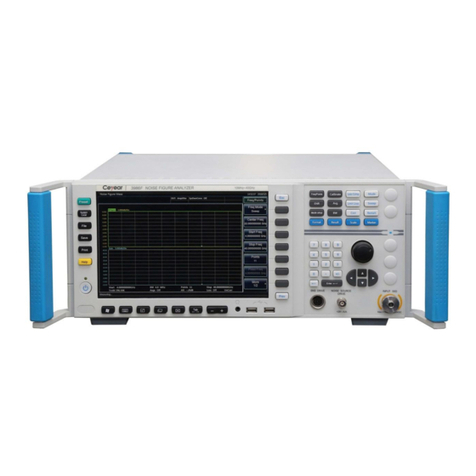
Ceyear 4024 Series User manual

4024 Series Spectrum Analyzer
User Manual


4024 Series Spectrum Analyzer
User Manual
AV2.731.1075SSCN


Environment and Safety Instructions
I. Safety Protection
1. Safety precautions for the instrument
1) Adopt designated packing container during handling, prevent instrument from falling down or fierce
collision which may result in damage;
2) Please do use the AC-DC adapter provided accompanying the instrument for power supply, or improper
power adapter will cause damage to the instrument.
3) Supply power to instrument with 220V AC three-core stabilized voltage power, prevent damaging
interior hardware due to high power spike pulse interference;
4) Ensure the good grounding of power supply as poor or wrong grounding may cause damage to the
instrument.
5) Take anti-electrostatic measures in operation, such as anti-electrostatic straps, to prevent electrostatic
damage to this instrument.
6) The DC signal above 16V and signal power above 30dBm are prohibited; otherwise, this instrument
may be damaged.
7) The battery used for powering up this instrument or installed in this instrument should be replaced with
one of the same type or recommended equivalent type; otherwise, explosion may occur.
8) It is not allowed to insert any solids into the instrument from opening of shell or pour any fluids into
inside or outside of shell to prevent interior short circuit and/or electric shock, fire or personal injury.
9) To prevent this instrument from overheating, the slot or opening for internal ventilation must not be
covered. It is prohibited to place the instrument in sofa, blanket or closed housing unless there is good
ventilation.
10) It is prohibited to place this product onto heating equipment such as the heater or heating fan. The
ambient temperature must not exceed the maximum temperature specified in this manual.
11) It is notable that when the instrument is in fire, toxic gas or liquid harmful to human being may be
released.
2. Safety precautions for other instrument & equipment
1) Check the working condition and turn off RF output before connecting the instrument, otherwise it may
output high power signal to damage the equipment to be tested;
2) The output power may be high in the self-test of this instrument. Please disconnect all external devices.
3) If the fault alarm is sent in operation of the spectrum analyzer, reminding the user of status anomaly,
you should turn off the RF switch or power switch and disconnect all external devices, so as to prevent the
influence on the tested equipment.
3. Personal safety precautions
1) It is requested to handle the instrument and packing container with proper tools and put them down
gently to prevent from personal injury due to instrument falling.
2) Ensure that the power supply is well grounded, as poor or wrong grounding may result in personal
injuries.
3) Get the instrument cut off before wiping to prevent electric shock; only wipe the outside of the
instrument with dry or slightly wet soft cloth other than the inside.
4) Instrument operator should have received special training before using the product and should be highly
focused during the using process. This instrument must be operated by physically and mentally appropriate
person. Otherwise, person injury or property loss may be caused.
5) This instrument has potential risks of microwave radiation in the high-power status. Please take
corresponding anti-radiation measures.
Environment and Safety Instructions
6) Prohibit using the instrument if the power line is found damaged. The power line should be checked on a
regular basis. Take safety precautions appropriately and place power line properly to ensure the power line
will not be damaged and personnel will not stumble over the power line or be shocked by electricity.
7) Prohibit using the instrumention open air in disastrous weather such as lightening to avoid damage to
instrument and human being.
8) It is not allowed to insert any solids into the instrument from opening of shell or pour any fluids into
inside or outside of shell to prevent interior short circuit and/or electric shock, fire or personal injury.
9) Similar to other industrial products, allergic materials (allergens such as aluminum) are unavoidable.
Once allergic reactions (such as rash, repeated sneezing, eye irritation or dyspnea) are detected, see a
doctor immediately and find out the reason. Note that toxic gas or liquid that is harmful to the human body
may be released once the instrument is on fire. In this case, the reasonable fire extinguishing measures
should be taken or the instrument should be taken away from the operation station.
10) The electromagnetic compatibility of the instrument conforms to the requirements of the specifications.
However, electromagnetic radiation may occur to some degree. The operator should check whether there
are special people vulnerable to such radiation in the working environment. If required, appropriate
measures should be taken to avoid hazards.
11) The instrument must be opened by the authorized personnel. The instrument should be powered off
before it is opened or operated in other way. Instrument adjustment, part replacement, maintenance and
repair must be done by the technical personnel of the manufacturer. Parts related to the safety must be
replaced with original parts.
II. Environmental Protection
1. Disposal of packing container
We are sure that pack container of products is harmless waste, please save packing container and liner for
future transportation or dispose them according to local environmental regulations.
2. Treatment of scrapped articles
1) The parts replaced in repair or upgrading should be recycled or dealt with by China Electronics
Technology Instruments Co., Ltd. The scrapped instrument must not be discarded or treated without
permission. Please notify China Electronics Technology Instruments or professional recycling units with
qualifications to recycle or deal with the scrapped instrument.
2) If required, the internal battery may not be discarded without permission after replacement. It should be
separately recycled as chemical waste.
Unless otherwise specified, the above-mentioned operations should abide by Regulations on Recovery
Processing of Waste Electrical and Electronic Products and local environmental laws and regulations.

Foreword
Thank you for choosing 4024 series spectrum analyzers developed and produced by China Electronics
Technology Instruments Co., Ltd.
We take customer demands as our own duty, providing you high-quality measuring instrument and the best
after-sales service. We always adhere to the business philosophy of "superior quality and considerate
service", and are committed to offering satisfactory products and service for our clients. Please contact us
according to the following information:
This manual introduces the purpose, operation method, operation precautions, performance characteristics,
basic operation principle and fault query of the 4024 series spectrum analyzer developed and produced by
China Electronics Technology Instruments Co., so as to help you to get familiar with and master the
operation method and key operation points as soon as possible. In order to skillfully operate this instrument,
please carefully read this manual and properly follow the guidance during operation.
The User Manual includes 13 chapters:
Chapter I briefly introduces the basic information of 4024 series spectrum analyzer, including main
technical characteristics, available or achievable functions and achievable technical specifications.
Chapter II to XI mainly describes the operating instructions. Chapter II describes what should be done after
receiving one new spectrum analyzer and what should be noted in operation. Chapter III mainly introduces
the front panel and external interfaces of the spectrum analyzer. Chapter IV introduces the spectrum
analysis measurement mode; Chapter V introduces the interference analysis measurement mode (optional);
Chapter VI introduces the power measurement mode (optional); Chapter VII introduces the analog
demodulation measurement mode (optional); Chapter VIII introduces the channel scanning measurement
mode (optional); Chapter IX introduces the field strength measurement mode (optional). Chapter X
introduces the Signal Analyzer mode (optional); Chapter XI and XII describe technical specifications. They
briefly describe the working principle of 4024 series spectrum analyzer, and provide the performance
characteristic test method of the main technical specifications.
Chapter XIII describes the maintenance requirements: Including the steps to query faults, error description
and repair procedures.
Due to our limited knowledge, there may be some omissions or errors, and you are welcome to correct any
Statement:
This manual is the fourth version of the User Manual of 4024 Series Spectrum
Analyzer.
The information contained in this User Manual is subject to change without
prior notice.
China Electronics Technology Instruments reserves the right of final
interpretation for the contents and terms used in this Manual.
Our company owns the copyright of this Manual. Without prior approval of it,
any unit or individual shall not modify or tamper the content of this Manual, or
reproduce or transmit this Manual for profit. Otherwise, China Electronics
Technology Instruments shall reserve the right to investigate legal liability
against the copyright infringer.

error. We are sorry for the flaws which may cause your inconvenience.
Editor
Sep. 2018

I
Contents
Chapter I Overview...............................................................................................................................................1
Section 1 Product Overview .............................................................................................................................2
1.1.1 Brief Introduction...................................................................................................................................2
1.1.2 Product features.....................................................................................................................................2
1.1.3 Functions................................................................................................................................................3
1.1.4 Typical application.................................................................................................................................3
Section 2 Main Technical Specifications .........................................................................................................5
Article I Instructions.............................................................................................................................................8
Chapter II Operation Guide............................................................................................................................... 10
Section 1 Unpacking Inspection.....................................................................................................................10
2.1.1 Model confirmation..............................................................................................................................10
2.1.2 Appearance inspection.........................................................................................................................10
Section 2 Safety Instructions ..........................................................................................................................10
2.2.1 Environmental requirements................................................................................................................10
2.2.2 Selection of power line.........................................................................................................................11
2.2.3 Power supply requirements..................................................................................................................11
2.2.4 Electrostatic protection (ESD).............................................................................................................12
2.2.5 Input/output port protection.................................................................................................................13
2.2.6 Cleaning of display of front panel........................................................................................................13
Section 3 Battery Installation and Replacement........................................................................................... 14
2.3.1 Battery description...............................................................................................................................14
2.3.2 Battery installation and replacement ...................................................................................................14
2.3.3 Battery status check..............................................................................................................................14
2.3.4. Battery charging..................................................................................................................................15
Section 4 User Inspection................................................................................................................................15
2.4.1 Start-up of spectrum analyzer ..............................................................................................................15
2.4.2 Shutdown of spectrum analyzer............................................................................................................15
Chapter III Basic Operation ..............................................................................................................................16
Section 1 Description of front panel...............................................................................................................16
3.1.1 Display zone.........................................................................................................................................16
3.1.2 Number input zone ...............................................................................................................................19
3.1.3 Function key zone.................................................................................................................................19
3.1.4 Reset button..........................................................................................................................................20
3.1.5 Power switch........................................................................................................................................20
Section 2 Interface Description ......................................................................................................................21
3.2.1 Power interface....................................................................................................................................21
3.2.2 Test ports..............................................................................................................................................21
3.2.3 Digital interface ...................................................................................................................................22
3.2.4 Instrument symbols...............................................................................................................................22
Chapter IV Spectrum Analysis Mode................................................................................................................24

II
Section 1 Introduction to Typical Measurements.........................................................................................25
4.1.1 Channel power measurement ...............................................................................................................26
4.1.2 Occupied bandwidth measurement.......................................................................................................28
4.1.3 Adjacent channel power ratio measurement ........................................................................................30
4.1.4 Third-order IM distortion measurement...............................................................................................32
4.1.5 Drift signal measurement .....................................................................................................................36
4.1.6 Noise signal measurement....................................................................................................................37
4.1.7 Distortion measurement .......................................................................................................................40
4.1.8 Pulse RF signal measurement ..............................................................................................................47
4.1.9 Signal source measurement (option).................................................................................................52
Section 2 Structure of Spectrum Analysis Menu..........................................................................................55
Section 3 Description of “Spectrum Analysis” Menu ...................................................................................61
4.3.1 Frequency menu ...................................................................................................................................61
4.3.2 Span menu ............................................................................................................................................62
4.3.3 IF output menu .....................................................................................................................................63
4.3.4 Amplitude menu....................................................................................................................................64
4.3.5 Bandwidth menu...................................................................................................................................65
4.3.6 Detector menu ......................................................................................................................................66
4.3.7 Marker menu ........................................................................................................................................67
4.3.8 Peak menu ............................................................................................................................................68
4.3.9 Mode menu...........................................................................................................................................69
4.3.10 Sweep menu........................................................................................................................................70
4.3.11 Triggering menu.................................................................................................................................71
4.3.12 Trace menu.........................................................................................................................................72
4.3.13 Limit menu..........................................................................................................................................73
4.3.14 Measurement menu.............................................................................................................................74
4.3.15. Signal source menu (option).........................................................................................................81
4.3.16 File menu............................................................................................................................................83
4.3.17 System menu.......................................................................................................................................83
Chapter V Interference Analyzer Measurement Mode (optional)..................................................................85
Section 1 Introduction to Typical Measurements.........................................................................................85
5.1.1 Spectrogram measurement...................................................................................................................85
5.1.2 RSSI measurement................................................................................................................................86
Section 2 Structure of Interference Analyzer Menu.....................................................................................88
Section 3 Description of Interference Analyzer Menu .................................................................................90
5.3.1 Frequency menu ...................................................................................................................................90
5.3.2 Span menu ............................................................................................................................................91
5.3.3 Amplitude menu....................................................................................................................................91
5.3.4 Bandwidth menu...................................................................................................................................92
5.3.5 Marker menu ........................................................................................................................................93
5.3.6 Peak menu ............................................................................................................................................94
5.3.7 Sweep menu..........................................................................................................................................95
5.3.8 Auto Save menu ....................................................................................................................................95
5.3.9 Measurement menu...............................................................................................................................96
5.3.10 File menu............................................................................................................................................96

III
Chapter VI Power Meter Mode (optional)........................................................................................................97
Section 1 Introduction to Typical Measurements.........................................................................................97
Section 2 Structure of Power Meter Menu....................................................................................................99
Section 3 Description of Power Meter Menu ..............................................................................................100
6.3.1 Frequency menu.................................................................................................................................100
6.3.2 Amplitude menu..................................................................................................................................100
6.3.3 Bandwidth menu.................................................................................................................................101
6.3.4 Calibrate menu...................................................................................................................................101
6.3.5 Limit menu..........................................................................................................................................101
6.3.6 File menu............................................................................................................................................102
Chapter VII AM-FM-PM Analyzer Mode (optional) .................................................................................... 103
Section 1 Introduction to Typical Measurements.......................................................................................103
Section 2 Structure of AM-FM-PM analyzer Menu...................................................................................105
Section 3 Description of AM-FM-PM Analyzer Menu ..............................................................................107
7.3.1 Frequency menu.................................................................................................................................107
7.3.2 Span menu..........................................................................................................................................108
7.3.3 Amplitude menu..................................................................................................................................108
7.3.4 Bandwidth menu.................................................................................................................................109
7.3.5 Marker menu......................................................................................................................................110
7.3.6 Peak menu..........................................................................................................................................111
7.3.7 RF spectrum menu..............................................................................................................................112
7.3.8 Audio spectrum menu.........................................................................................................................112
7.3.9 Audio waveform menu........................................................................................................................113
7.3.10 Measurement menu ..........................................................................................................................113
7.3.11 File menu..........................................................................................................................................113
Chapter VIII Channel Scanner Mode (optional)............................................................................................ 115
Section 1 Introduction to Typical Measurements.......................................................................................115
8.1.1 Channel Scanner................................................................................................................................115
8.1.2 Frequency Scanner.............................................................................................................................116
8.1.3 List scanner........................................................................................................................................117
Section 2 Structure of Channel Scanner Menu...........................................................................................118
Section 3 Description of Channel Scanner Menu .......................................................................................119
8.3.1 Scanner menu.....................................................................................................................................119
8.3.2 Channel Scanner menu ......................................................................................................................119
8.3.3 Frequency Scanner menu...................................................................................................................120
8.3.4 List Scanner menu..............................................................................................................................120
8.3.5 Measurement menu ............................................................................................................................121
8.3.6 File menu............................................................................................................................................121
Chapter IX Field Strength Measurement Mode (optional) ...........................................................................123
Section 1 Introduction to Typical Measurements.......................................................................................123
9.1.1 PScan .................................................................................................................................................123
9.1.2 FScan .................................................................................................................................................124
9.1.3 MScan ................................................................................................................................................124

IV
Section 2 Structure of Field Strength Menu................................................................................................126
Section 3 Description of Field Strength Menu ............................................................................................128
9.3.1 Frequency menu ([PScan] mode).......................................................................................................128
9.3.2 Frequency menu ([FScan] mode).......................................................................................................128
9.3.3 Amplitude menu..................................................................................................................................129
9.3.4 Bandwidth menu.................................................................................................................................130
9.3.5 Marker menu ......................................................................................................................................130
9.3.6 Peak menu ..........................................................................................................................................130
9.3.7 Sweep/Antenna menu..........................................................................................................................131
9.3.8 Edit List menu.....................................................................................................................................131
9.3.9 Demodulation menu ...........................................................................................................................132
9.3.10 Measurement menu...........................................................................................................................132
9.3.11 File menu..........................................................................................................................................132
Chapter X Signal analyzer mode (option).................................................................................................133
Section 1 Introduction to typical measurement......................................................................................133
Section 2 Structure of signal analysis menu............................................................................................136
Section 3 Description of signal analysis menu ........................................................................................138
10.3.1 Frequency menu .........................................................................................................................138
10.3.2 Span menu...................................................................................................................................139
10.3.3 Amplitude menu..........................................................................................................................139
10.3.4 Bandwidth menu .........................................................................................................................140
10.3.5 Marker menu...............................................................................................................................141
10.3.6 Peak menu...................................................................................................................................142
10.3.7 Sweep menu ................................................................................................................................143
10.3.8 Record menu...............................................................................................................................143
10.3.9 Configuration menu....................................................................................................................144
10.3.10 Tune Listen menu........................................................................................................................144
10.3.11 IQ Capture menu ........................................................................................................................145
10.3.12 ShortCut menu............................................................................................................................146
10.3.13 File menu....................................................................................................................................146
Article II Technical Instructions......................................................................................................................147
Chapter XI Operating Principle.......................................................................................................................149
Chapter XII Performance Characteristic Test ...............................................................................................151
Article III Maintenance Instructions...............................................................................................................184
Chapter XIII Troubleshooting and Repair .....................................................................................................186
Section 1 Fault Information Description .....................................................................................................186
Section 2 Repair Method...............................................................................................................................187
Appendix A Performance Characteristic Test Results...................................................................................188

V


Chapter I Overview
1
Chapter I Overview
The following safety notes are used throughout this manual. Familiarize yourself with each of the notes and
its meaning before operating this instrument.
“Warning” indicates danger. It reminds the user to pay attention to a certain
operation process, operation method or similar situations. Noncompliance with the
rules or improper operation may result in personal injuries. You shall fully
understand and meet all the conditions in the warning before proceeding to the next
step.
“Attention” indicates important prompts and no danger. It reminds the user to pay
attention to a certain operation process, operation method or similar situations.
Noncompliance with the rules or improper operations may result in damage to the
instrument or loss of important data. You shall fully understand and meet all the
conditions in the caution before proceeding to the next step.
Warning
!
Caution

Chapter I Overview
2
Section 1 Product Overview
1.1.1 Brief Introduction
4024 series spectrum analyzer has the advantages of broad operating band, high performance specifications,
high sweeping speed, multiple test functions, easy operation, etc. From the perspective of performance
specifications, this instrument has low average noise level, low phase noise and high scanning speed. From
the perspective of measurement functions, this instrument has various measurement modes such as
spectrum analysis, interference analysis, analog demodulation, power measurement, channel scanning and
field strength measurement and various intelligent measurement functions such as the channel power,
occupied bandwidth, adjacent channel power, tune listening, emission mask and C/N. Due to integration of
the 8.4-inch LCD and capacitive touch screen, the display definition and operational convenience are
improved. This instrument has a small and light structure, and can be flexibly powered up and easily
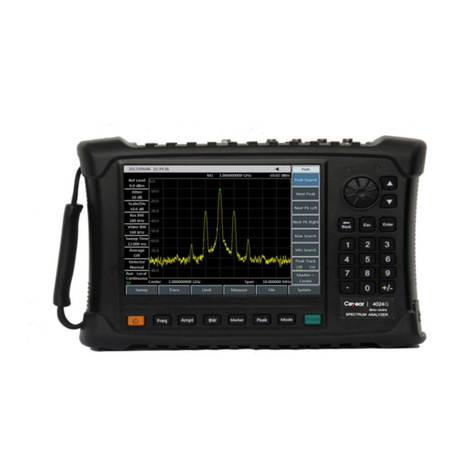
operation. Therefore, this instrument is applicable to field operation. The appearance is shown in Fig. 1-1.
Fig. 1-1 4024 Series Spectrum Analyzer
1.1.2 Product features
Based on the highly integrated, modular and standardized design, 4024 series spectrum analyzer has
excellent performance, with main characteristics as follows:
Broad frequency coverage: 4 models from 9kHz to 44GHz;
Low average noise level: -157dBm@1Hz RBW;
Excellent phase noise performance: -106dBm/Hz@100kHz; offset: @1GHz carrier;
High sweeping speed: Minimum sweeping time within 1GHz span: <20ms;
Resolution bandwidth: 1Hz~10MHz;
Tracking Generator:4GHz,6.5GHz,9GHz;
Full-band pre-amplifier: Standard configuration;

Chapter I Overview
3
Various measurement modes: Spectrum analysis, interference analysis (spectrogram and RSSI),
analog demodulation (AM/FM/PM), channel scanning, high-precision USB power measurement, field
strength measurement, etc.
Various intelligent measurement functions: Field strength measurement, channel power, occupied
bandwidth, adjacent channel power, audio demodulation, carrier-noise ratio, emission mask, IQ
capture, etc.
Various auxiliary test interfaces: 10MHz reference input/output interface, GPS antenna interface,
zero-span IF output interface, external trigger input interface, etc.
Convenient and fast user operation experience: 8.4-inch large-screen high-brightness LCD, large-font
display, convenient capacitive touch screen, LCD and touch screen integration, various display modes,
automatic adjustment of backlight brightness, etc.
Operating temperature range: -10°C to 50°C this instrument can be powered up with the battery or
adapter.
1.1.3 Functions
4024 series spectrum analyzer has a wide range of measurement functions, mainly including:
Spectrum analysis, used for basic spectrum analysis of signals, including various intelligent
measurement functions such as the field strength measurement, channel power, occupied bandwidth,
adjacent channel power, emission mask, carrier-noise ratio, audio demodulation and IQ capture;
Listing scanning (optional), used for continuous scanning measurement of multiple bands;
Interference analysis (optional), including spectrogram and RSSI measurement;
Analog demodulation, used for analysis of modulation characteristics of AM/FM/PM signals;
Power measurement, used for high-precision power measurement of the USB interface;
Channel scanning (optional), used for signal power measurement of multiple channels or frequencies;
Field strength measurement (optional), used for CW measurement, frequency scanning measurement
and list scanning measurement;
GPS positioning (optional), realized with the external GPS antenna;
Zero-span IF output (optional), used for output of the IF output interface under zero span;
Tracking Generator(optional),used for output of Generator or Tracking Generator.
1.1.4 Typical application
■ On-site comprehensive performance evaluation of electronic weapon equipment
4024 series spectrum analyzer has the advantages of broad operating band, high performance specifications,
high sweeping speed, multiple test functions, easy operation, etc. In addition, this handheld instrument is
small and light and can be powered up with the battery. Therefore, this instrument can be applied in on-site
installation/commissioning and maintenance/guarantee of various kinds of electronic weapon equipment
such as the radar, communication, electronic countermeasures and reconnaissance and precision guidance.
■ On-site testing and diagnosis of transmitter and receiver

Chapter I Overview
4
4024 series spectrum analyzer has various measurement modes such as the spectrum analysis, interference
analysis, analog demodulation, power measurement, channel scanning and field strength measurement, and
various intelligent measurement functions such as the channel power, occupied bandwidth, adjacent
channel power, C/N, field strength and emission mask. Therefore, it can be used for comprehensive
spectrum analysis and diagnosis services in on-site testing of transmitters and receivers.
■ Broadband spectrum monitoring and interference identification
4024 series spectrum analyzer can be applied with the external directional antenna in electromagnetic
environment detection, radio interference analysis, electromagnetic environment background evaluation,
spectrum monitoring, identification of illegal channel interference signals, etc.
Other manuals for 4024 Series
2
This manual suits for next models
7
Table of contents
Other Ceyear Measuring Instrument manuals

Ceyear
Ceyear 4024 Series User manual

Ceyear
Ceyear 3656 Series User manual

Ceyear
Ceyear 4957D User manual

Ceyear
Ceyear 2438 Owner's manual

Ceyear
Ceyear 2498C User manual

Ceyear
Ceyear 3986 Series User manual

Ceyear
Ceyear 3986 Series Owner's manual

Ceyear
Ceyear 3680A User manual

Ceyear
Ceyear 4051 Series User manual

Ceyear
Ceyear 87234 Series User manual