Ceyear 4041 Series User manual

4041 Series Spectrum Analyzer
User Manual
China Electronics Technology Instruments Co., Ltd.


4041 Series Spectrum Analyzer
User Manual
2.731.1098SSCN
China Electronics Technology Instruments Co., Ltd


Foreword
Thanks a lot for choosing the 4041 series spectrum analyzer developed and manufactured by CETI.
We are devoted to providing for you high-quality products and first-class after-sales service with your most
concerns and demands in mind. Following the consistent tenet of “High Quality and Considerable Service”, we
are committed to provide for our customers satisfactory products and services. For any questions, please contact
us:
Tel +86-0532-86896691
Website www.ceyear.com
Address: No.98 Xiangjiang Road, Qingdao City, China
Postcode 266555
This manual describes the applications, operation instructions, notices of use, performance characteristics, basic
working principle, fault diagnosis and other directions regarding the 4041 series spectrum analyzer developed and
manufactured by CETI, enabling you to get familiar with the operation methods and key points of use as soon as
possible. For a proper use of this instrument, please carefully read and strictly follow this manual.
This manual consists of 12 chapters:
Chapter I describes the basic information of the 4041 series spectrum analyzer, including main technical features,
already available or potentially available functions, and technical specifications.
Chapters II~IX mainly covers operation instructions. Specifically speaking, Chapter II describes the method to
handle a newly-received spectrum analyzer and the notices for use. Chapter III mainly introduces the front panel
and external interfaces of the unit. Chapter IV, Chapter V, Chapter VI, Chapter VII, Chapter VIII and Chapter IX
respectively introduce the Spectrum Analyzer measurement mode, Interference Analyzer measurement mode
(option), Power meter mode (option), AM/FM/PM analyzer measurement mode (option), Channel scanner
measurement mode (option) and field strength measurement mode (option) of the 4041 series spectrum analyzer.
Chapters X and XI contain technical instructions, including brief description of working principle, as well as main
technical specifications and test methods of performance characteristics.
Statements
This is the first version of User Manual for 4041 Series Spectrum Analyzer.
This manual may be subject to change without notice.
CETI reserves all the rights to the final explanation for all the information and
terminologies referred to in this manual.
This manual is the property of CETI. Without our permission, any
organizations or individuals shall neither alter/temper nor duplicate/transmit
this manual for profits; otherwise, CETI reserves the right to pursue any
liabilities therefrom.

Chapter XII contains maintenance instructions, including fault diagnosis steps, fault information description and
repair methods.
However, due to limitations of the author, the manual may be subject to errors or deficiencies. We sincerely
welcome your corrections! We apologize for any inconvenience caused by our mistake in our work.
The Author
Oct. 2018

Environment and Safety Instructions
I. Safety Protection
1. Safety precautions for the instrument
1) Please use the designated packaging box for transportation, and protect the instrument against damage from
dropping or violent impacting.
2) Please select 100 V~120 V or 200 V~240 V AC 3-core stabilized power supply, so as to prevent the internal
hardware from being damaged by high-power peak pulse interference.
3) Keep the power supply properly grounded, as improper or wrong grounding may lead to unit damage.
4) Wear anti-electrostatic wrist or take other anti-electrostatic measures when operating the unit, so as to
prevent the unit from being damaged by the static electricity.
5) Avoid signals above 16 VDC, and prevent the signal power from exceeding 30 dBm; otherwise, the unit may
be damaged.
6) Neither insert any objects from the opening on the housing of unit nor pour fluids on or into the unit;
otherwise, short circuit may occur inside the unit and cause electrical shock, fire hazard or personal injury.
7) Never cover the grooves or openings that serve for internal ventilation on the unit; otherwise, the unit may
become overheated. Never place the unit on sofa, blanket or in a closed enclosure, unless a good ventilation
is provided.
8) Never place the unit on the heater, heating fan or other heat sources, and ensure that the ambient temperature
is not above the maximum temperature specified in this manual.
9) Please note that, the unit, once catching fire, may emit toxic gases or fluids that are harmful to human health.
2. Safety precautions for other instrument & equipment
1) Before connecting this unit, check its working condition and switch off the RF output, so as to prevent the
tested device from being damaged by the high-power signals output by the unit.
2) As the unit may output a higher power during self-test, please disconnect all the external equipment in this
case.
3) If, during the use of the spectrum analyzer, a fault warning indication occurs to tell the user that the spectrum
analyzer involves an abnormality, please turn off the RF switch or power switch and disconnect all the
external equipment to eliminate any possible influences on the tested device.
3. Personal safety precautions
1) Use a proper tool to transport the unit and its packaging box, and handle it gently to prevent personal injury
when the unit drops.
2) Keep the power supply properly grounded, as improper or wrong grounding may lead to personal injury.
3) When it becomes necessary to wipe off the unit, please power it off in advance to prevent hazard of electrical
shock. It is allowed to wipe the outside of unit using a dry or slightly wet soft cloth, and never attempt to
wipe its inside.
4) Any operator shall receive professional training before use, and be highly concentrated during use. The
operator of the unit shall be sound in body and mind; otherwise, personal injury or property loss may occur.
5) As the unit involves potential hazard of microwave radiation when working at a high power, please take
corresponding radiation prevention measures.
6) Never use the unit when its power line is damaged. Please check on a regular basis if the power line is
normal. Take appropriate safety protection measures and place the power line in such a proper way that it
will not be damaged and anybody will not be stumbled or electrocuted by the power line.
7) Never use the unit outdoors in bad weather like thunderstorm, so as to prevent unit damage or personal
injury.
8) Neither insert any objects from the opening on the housing of unit nor pour fluids on or into the unit;

otherwise, short circuit may occur inside the unit and/or cause electrical shock, fire hazard or personal injury.
9) Like other industrial products, the use of allergic materials (allergens including aluminum) is inevitable. In
case of any anaphylactic reaction (for instance, rash, repeated sneezes, eye irritation or breath with difficulty),
please seek medical advice immediately to find out the causes. Please note that, the unit, once catching fire,
may emit toxic gases or fluids that are harmful to human health. In this case, please take reasonable
fire-fighting measures or evacuate from the operation station.
10) This product, though in compliance with the EMC-related specifications, still has some electromagnetic
radiation. Considering this, the user shall confirm if there are any personnel vulnerable to such radiation in
the working environment, and when necessary, take corresponding preventive measures.
11) This product can be opened only by the authorized personnel. Before opening the unit or performing other
operations to it, cut off the power supply first. Only the technician of the manufacturer can perform such
operations as instrument adjustment, part replacement, maintenance or repair, and when a safety-related parts
needs replacement, always use the original part.
II. Environment protection
1. Disposal of packing container
We are committed that the package of this product contains no harmful materials. Please keep well the packaging
box and linings for transport purpose in the future; or, dispose the packages according to the local environment
regulations.
2. Treatment of scrapped articles
Parts replaced during maintenance and upgrade of this instrument are to be recovered by CETI; when the
instrument comes to the end of its service life, never throw or dispose it at will, and instead, please inform CETI
or other qualified recycling unit for recycle.
Unless otherwise specified, please follow Regulation on the Administration of the Recovery and Disposal of
Waste Electrical and Electronic Products and local environment regulations.

Table of Contents
CONTENTS
CHAPTER I OVERVIEW ........................................................................................................................... 1
Section 1 Product Overview................................................................................................................... 2
Section 2 Main Technical Specifications................................................................................................ 5
ARTICLE I INSTRUCTIONS...................................................................................................................... 8
CHAPTER II USER GUIDE ..................................................................................................................... 10
Section 1 Self-inspection after Unpacking............................................................................................ 10
Section 2 Safety Instructions................................................................................................................ 10
Section 3 User Checks......................................................................................................................... 13
CHAPTER III BASIC OPERATIONS....................................................................................................... 14
Section 1 Introduction to Front Panel................................................................................................... 14
Section 2 Introduction to Interfaces...................................................................................................... 19
CHAPTER IV SPECTRUM ANALYZER MODE ..................................................................................... 22
Section 1 Introduction to Typical Measurement................................................................................... 24
Section 2 Spectrum Analyzer Menu Structure..................................................................................... 55
Section 3 Description of Spectrum Analyzer Menu.............................................................................. 60
CHAPTER V INTERFERENCE ANALYZER MEASUREMENT MODE (OPTION)................................ 82
Section 1 Introduction to Typical Measurement................................................................................... 82
Section 2 Interference Analyzer Menu Structure ................................................................................. 85
Section 3 Description of Interference Analyzer Menu.......................................................................... 87
CHAPTER VI POWER METER MODE (OPTION).................................................................................. 94
Section 1 Introduction to Typical Measurement................................................................................... 94
Section 2 Power Meter Menu Structure ............................................................................................... 96
Section 3 Description of Power meter Menu........................................................................................ 97
CHAPTER VII AM-FM-PM ANALYZER MODE (OPTIONAL).............................................................. 100
Section 1 Introduction to Typical Measurement................................................................................. 100
Section 2 AM/FM/PM analyzer Menu Structure.................................................................................102
Section 3 Description of AM/FM/PM analyzer Menu..........................................................................104
CHAPTER VIII CHANNEL SCANNER MODE (OPTION) .................................................................... 110
Section 1 Introduction to Typical Measurement................................................................................. 110
Section 2 Structure of the Channel scanner Menu............................................................................114
Section 3 Description of Channel scanner Menu...............................................................................115
CHAPTER IX FIELD STRENGTH MEASUREMENT MODE (OPTION).............................................. 118
Section 1 Introduction to Typical Measurement................................................................................. 118
Section 2 Field Strength Measurement Menu Structure....................................................................121
Section 3 Description of the Field Strength Measurement Menu ......................................................123
ARTICLE II TECHNICAL INSTRUCTIONS........................................................................................... 130
CHAPTER X WORKING PRINCIPLE................................................................................................... 132
CHAPTER XI PERFORMANCE CHARACTERISTICS TEST.............................................................. 134
11.1 Frequency range.........................................................................................................................137

Table of Contents
11.2 Frequency readout accuracy......................................................................................................138
11.3 Span accuracy............................................................................................................................139
11.4 Sweep time.................................................................................................................................141
11.5 RBW............................................................................................................................................142
11.6 RBW switching uncertainty......................................................................................................... 144
11.7 Sideband noise...........................................................................................................................145
11.8 Displayed average noise level....................................................................................................146
11.9 Second harmonic distortion........................................................................................................ 150
11.10 Third-order intermodulation distortion...................................................................................... 152
11.11 1dB gain compression.............................................................................................................. 157
11.12 Image, Multiple, and Out-of-band Responses .........................................................................159
11.13 Residual response.................................................................................................................... 161
11.14 Reference level.........................................................................................................................164
11.15 Scale fidelity.............................................................................................................................. 166
11.16 Total level uncertainty............................................................................................................... 167
11.17 Input attenuator.........................................................................................................................169
11.18 Input voltage standing wave ratio test...................................................................................... 170
11.19 Maximum fail-safe input level................................................................................................... 171
11.20 Displayed scale.........................................................................................................................171
11.21 Video BW.................................................................................................................................. 171
ARTICLE III MAINTENANCE INSTRUCTIONS.................................................................................... 173
CHAPTER XII FAULT INFORMATION DESCRIPTION AND REPAIR METHODS............................ 175
Section 1 Fault Information Description .............................................................................................175
Section 2 Repair Methods..................................................................................................................175
APPENDIX A TEST RESULTS OF PERFORMANCE CHARACTERISTICS...................................... 176

Chapter I Overview
1
Chapter I Overview
For the purpose of this manual, the following safety symbols apply, and please be familiar with them and their
meanings before operating this instrument!
A “WARNING” sign indicates for an existing danger. It reminds the user to pay
attention to a certain operation process, operation method or the similar. Any
violation against the indicated rules or incorrect operation may lead to personal
injury. It is not allowed to proceed until the warning conditions are fully
comprehended and satisfied.
A “CAUTION” sign provides prompt on important information but not dangerous
situations. It reminds the user to pay attention to a certain operation process, operation
method or the similar. Any violation against the indicated rules or incorrect operation
may lead to instrument damage or loss of important data. It is not allowed to proceed
until the cautioning conditions are fully comprehended and satisfied.
CAUTION
WARNING
!
!

Chapter I Overview
2
Section 1 Product Overview
1.1.1 Introduction
The 4041 series spectrum analyzer is adopted with the compact portable box structure, which has advantages of
small size, light weight, low power consumption and convenient carrying. The broadband millimeter-wave
receiver miniaturization integrated design technology, whole phase locking technology based on the broadband
VCO, full digital intermediate frequency design technology, and microwave composite multilayer circuit board
design technology are adopted for this product, thus realizing high performance specifications and ensuring the
economical efficiency of the product. The 4041 spectrum analyzer series currently consists of four types of
products. The frequency measurement range covers 9kHz~20GHz, 9kHz~26.5GHz, 9kHz~32GHz and
9kHz~44GHz respectively. The full spectrum of the product is equipped with a preamplifier, so that it has very
high receiving sensitivity at any frequency point. In addition, with the 12.1-inch high brightness LCD and
integrated design of capacitive touch screen, large button and virtual button combination design, its operation
convenience is improved. For its performance specifications, it has excellent average noise level and phase noise
indicator as well as the high scanning speed. For its measurement function, it has the option modes including the
Interference Analyzer, channel scanner, AM/FM/PM analyzer, and USB Power meter, as well as a variety of
measurement functions including the channel power, occupied bandwidth, adjacent channel power, audio
demodulation, emission mask and carrier-to-noise ratio. This product can be used for the test and maintenance of
the aviation, spaceflight, wireless communications and radar signals and devices, and it can also be used for the
research, development and production of electronic products and the teaching experiment of scientific research
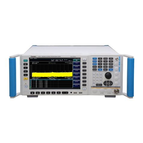
institutes. For its outline, see Fig 1-1 below.
Fig 1-1 4041 Series Spectrum Analyzer
1.1.2 Characteristics
The 4041 series spectrum analyzer is designed on the concept of highly integration, modularization and
standardization and boasts excellent performance. Its main characteristics are described below:

Chapter I Overview
3
A portable case characterized by thin thickness and light weight, which can be conveniently placed and
carried;
Wide frequency range covering 9kHz~20GHz/26.5GHz/32GHz/44GHz; with the full frequency preamplifier
as standard;
High sensitivity, and a Min. DANL of -163 dBm@1 Hz RBW (with preamplifier on);
Phase noise indicator (1 GHz carrier): -106 dBc/Hz@100 kHz frequency offset;
Resolution bandwidth: 1 Hz~10 MHz;
Extremely high sweep speed: Minimum sweep time@ 1 GHz span <20 ms;
Various measurement functions, such as the channel power, occupied bandwidth, adjacent channel power,
audio demodulation, carrier-to-noise ratio, and emission mask.;
Abundant test function mode options: Interference Analyzer (spectrogram, RSSI), AM/FM/PM analyzer
(AM/FM/PM), Channel scanner, and high-precision USB Power meter, etc.;
Easy to operate, equipped with 12.1-inch high brightness LCD screen featuring large font display and loose
button layout, and supporting the capacitive touch screen operation and touch screen marker dragging.
1.1.3 Functions
The 4041 series spectrum analyzer is featured with abundant measurement functions, mainly including:
Spectrum Analyzer function, which allows basic Spectrum Analyzer to the signals, including field strength
measurement, channel power, occupied bandwidth, adjacent channel power, emission mask, carrier-to-noise
ratio, audio demodulation, IQ capture, tracking generation and other intelligent measurement functions;
List sweep function (option), which allows the continuous scanning measurement of multiple frequency
bands;
Interference analyzer function (option), which provides functions including the spectrogram and RSSI
measurement;
AM/FM/PM analyzer function (option), which allows the modulation characteristics analysis of the
AM/FM/PM signals;
Power meter function (option), which allows high-precision USB Power meter;
Channel scanner function (option), which allows signal Power meter of multiple channels or frequencies;
Field strength measurement function (option), which allows dot frequency measurement, frequency scanning
measurement and list scanning measurement;
GPS positioning function (option), which realizes GPS positioning through an external GPS antenna;
Zero span intermediate frequency output function (option), which realizes output of third/fourth-intermediate
frequency at zero span through the intermediate frequency output interface.
1.1.4 TypicalApplications
■Test of Components and Parts
It can be used for the test of parameters and specifications including the gain, frequency response, frequency
conversion loss and insertion loss of the components and modules including the amplifier, filter, mixer, attenuator,
cable and directional coupler.

Chapter I Overview
4
■Test and Diagnosis of the Transmitter and Receiver
The 4041 spectrum analyzer has a number of measurement function modes including the Spectrum Analyzer,
Interference Analyzer, AM/FM/PM analyzer, USB Power meter, and Channel scanner, and it also has a number of
measurement functions including the channel power, occupied bandwidth, adjacent channel power,
carrier-to-noise ratio, field strength, and emission mask; therefore, it can provide the comprehensive Spectrum
Analyzer and diagnosis service for the test of the transmitter and receiver.

Chapter I Overview
5
Section 2 Main Technical Specifications
The 4041 series spectrum analyzer has been subject to strict test of technical specifications before delivery, and
the user can choose to prove the technical specifications given in this manual by test. For the main technical
specifications of the 4141 series spectrum analyzer, see the Table 1-1 below.
The 4041 series spectrum analyzer, after being stored at ambient temperature 2h and
then preheated for 30 min, meet all the technical specifications within the given
working temperature range.
Additional features expressed by typical values are for reference only, and does not
constitute subject of proof.
Table 1-1 Technical Specifications of 4041 Series Spectrum Analyzer
Test Item
Technical Specifications
Model
4041D/E/F/G
Frequency range
4041D: 9 kHz~20 GHz 4041E: 9 kHz~26.5 GHz
4041F: 9 kHz~32 GHz 4041G: 9 kHz~44 GHz
Tuning resolution: 1 Hz
Frequency reference
Nominal frequency: 10 MHz
Frequency reference error: (Time to last calibration date × Aging rate +
Temperature stability + Calibration accuracy)
Aging rate: 510-7/year
Temperature stability: 110-7 (0°C 50°C, relative to 255°C)
Initial calibration accuracy: 310-7
Note: The time to last calibration date is 1 year by default
Frequency readout accuracy
(frequency reading × frequency reference error +2% × span +10% ×
resolution bandwidth)
Frequency span
Range: 100 Hz~The upper limit of the frequency of the corresponding model;
0 Hz (zero span)
Tuning resolution: 1 Hz
Accuracy: ±2.0%
Sweep Time
Range: 10 μs~600 s (zero span)
Accuracy: ±2.00% (zero span)
Resolution Bandwidth
Range: 1 Hz~10 MHz (1-3 times step)
Accuracy (3.0 dB): ±10% 1 kHz~3 MHz
±20% 10 MHz
Resolution bandwidth change
uncertainty
1.00 dB 1 Hz~10 MHz (reference: 100 kHz RBW)
CAUTION

Chapter I Overview
6
Video Bandwidth
1 Hz~10 MHz (1-3 times step)
SSB phase noise
(Carrier 1 GHz, 20℃~30℃)
≤-102 dBc/Hz@10 kHz frequency offset
≤-106 dBc/Hz@100 kHz frequency offset
≤-111 dBc/Hz@1MHz frequency offset
≤-123 dBc/Hz@10MHz frequency offset
Displayed average noise level
(Tracking Generator off, 50 Ω
input end load, 0 dB input
attenuation, average detection,
video type logarithm, RBW
normalized to 1 Hz, 20℃30℃)
Preamplifier off
≤-135 dBm (2 MHz~10 MHz) ≤-138 dBm (10 MHz~20 GHz)
≤-135 dBm (20 GHz~32 GHz) ≤-127 dBm (32 GHz~40 GHz)
≤-120 dBm (40 GHz~44 GHz)
Preamplifier on
≤-150 dBm (2 MHz~10 MHz) ≤-157 dBm (10 MHz~20 GHz)
≤-154 dBm (20 GHz~32 GHz) ≤-148 dBm (32 GHz~40 GHz)
≤-140 dBm (40 GHz~44 GHz)
Second harmonic distortion
(0 dB attenuation, -30 dBm input
signal)
<-60 dBc
Third-order intermodulation
distortion
(-15 dBm double tone signal, 100
kHz interval, 0 dB attenuation,
preamplifier off)
≥+7 dBm 50 MHz~4 GHz
≥+6 dBm 4 GHz~13 GHz
≥+6 dBm 13 GHz~44 GHz
1 dB gain compression
(Dual-tone method test, signal
interval 10 MHz)
≥-2 dBm 50 MHz~4 GHz
≥-3 dBm 4 GHz~13 GHz
≥-3 dBm 13 GHz~44 GHz
Image, multiple and out-of-band
response
(-10 dBm mixer level)
≤-65 dBc 10 MHz~20 GHz
≤-60 dBc 20 GHz~44 GHz
Residual response
(RF input matching, 0 dB
attenuation, Tracking Generator
off)
Exceptional frequency point 3,200 MHz
Preamplifier on:
≤-100 dBm 10 MHz~20 GHz
≤-95 dBm 20 GHz~44 GHz
Preamplifier off:
≤-90 dBm 10 MHz~13 GHz
≤-85 dBm 13 GHz~20 GHz
≤-80 dBm 20 GHz~44 GHz
Scale fidelity
±1.00 dB
Total level uncertainty
±1.8 dB (10 MHz~13 GHz)

Chapter I Overview
7
(after 30 minute warm-up,input
signal 0 dBm ~-50 dBm, all set as
auto coupling,20℃~30℃)
±2.3 dB (13 GHz ~40 GHz)
Input attenuator
Attenuation range: 0 dB~50 dB, 10 dB step
Switching uncertainty: ±1.20 dB
Maximum safe input level
(CW input)
+30dBm, typical value (≥10dB attenuation, preamplifier off )
+23dBm, typical value (<10dB attenuation, preamplifier off )
+13dBm, typical value (preamplifier on)
Reference Level
Logarithmic scale: -120 dBm~+30 dBm, 1 dB step
Linear scale: 22.36 uV~7.07 V, 0.1% step
Switching uncertainty: ±1.20 dB (reference level: 0 dBm~-60 dBm)
Video Bandwidth
1 Hz~10 MHz (1-3 times step)
Input voltage standing-wave ratio
(>10 dB input attenuation)
≤ 1.80:1 50 MHz~20 GHz
≤ 2.20:1 20 GHz~44 GHz

8
Article I Instructions
This manual suits for next models
4
Table of contents
Other Ceyear Measuring Instrument manuals

Ceyear
Ceyear 3680A User manual

Ceyear
Ceyear 3986 Series User manual

Ceyear
Ceyear 3672 Series User manual

Ceyear
Ceyear 87234 Series User manual

Ceyear
Ceyear 4024 Series User manual

Ceyear
Ceyear 2498C User manual

Ceyear
Ceyear 2438 Owner's manual

Ceyear
Ceyear 4024 Series User manual

Ceyear
Ceyear 4957D User manual

Ceyear
Ceyear 4024 Series User manual