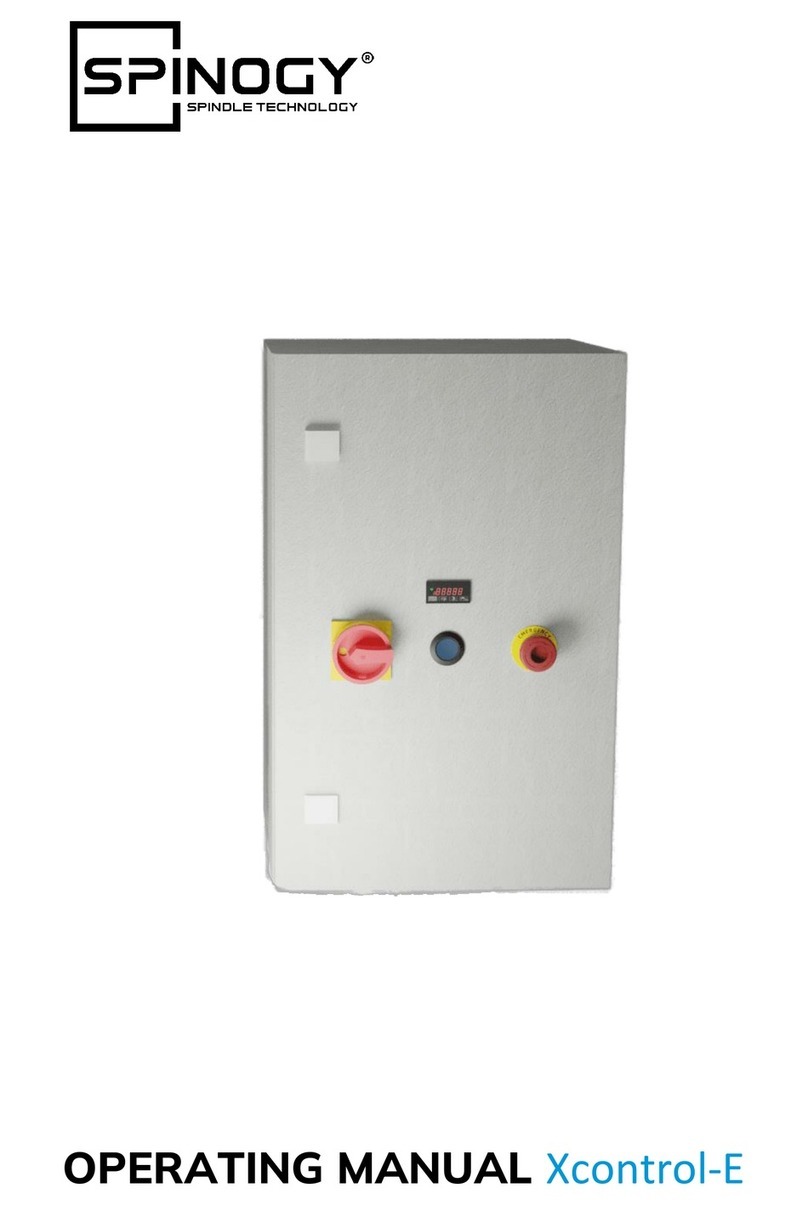
CGG P02 User manual

General characteristics
P02 - PTRM Series pendant stations
for small hoist applications
P03 Series pendant stations
for small hoist applications
Single row PL Series pendant stations
for control circuits
Double row PLB Series pendant stations
for control circuits
PL - PLB Series - Pendant stations
for control circuits - Enclosures pendant
stations single products and Accessories
PL - PLB Series pendant stations for
control circuits, Configuration and Symbols
PL - PLB Series pendant stations
for control circuits, Assembly
DC16 Series pendant stations
for small hoist applications
DC30 Series pendant stations
for direct switching power circuits
Pendant stations for control circuits
and power circuits - Schemes
TLP light Series - Pendant stations
General and electricals characteristics
11
Table of contents
TECHNO-LIFTING EQUIPMENT
Pendant stations for small hoist application for control circuits,
in both single or double row version for control circuits and direct switching
power circuits, for tail lift control.
Pendant stations
Table of contents
pag. 12
pag. 13
pag. 14
pag. 16
pag. 17
pag. 18
pag. 20
pag. 22
pag. 24
pag. 25
pag. 27
pag. 28
pag. 31
P02 - PTRM - P03 - PL - PLB - DC16 - DC30 - TLP Series

P02 - PTRM - P03 - PL - PLB - DC16 - DC30 - TLP Series
Characteristics
12
Pendant stations
Small hoist application
For auxiliaries circuits
Direct command
Bower circuit
Push button station for tail lifts
GENERAL CHARACTERISTICS
Giovenzana International Company, leader in lifting equipment control, made a wide range
of standard products for all installation requirements with actual specification and safety guidelines.
The Lift Equipments products serie are classified as: Giovenzana International Company, made a wide
range of standard products for all installation requirements with actual specification and safety guidelines.
The Lift Equipment products serie are classified as: IEC 947-5-1, EN60947-5-1, UL508 and job:
IEC 204-1, EN60204-1, EN ISO 13850 comply with achieved according to the needs and requirements
operator are classified in 5 Product Family:
All operators are colored or symbology in laser engraving comply with EN60204-1 e FEM 9.941
CERTIFICATIONS:
The pendant stations P02, P03, PL e PLB Series are Certificated cuL.

208 - 8.18"
268 - 10.55"
2.28" 80 - 3.15"
2.36"
60
58
Ø 11
Ø 9
Ø7
Ø 14
Pendant stations
TECHNO-LIFTING EQUIPMENT
13
n° 1 emergency stop EN ISO 13850
mushroom Ø 30
turn to release
230
For single speed motor control
Arranged execution for
capacitor 45X90 Ø Max
n° 1 two way
and off switch
with spring return
16A - 250V ac 1/2 HP
PTRM
230
250
250
250
230
For single speed motor control
For two-speeds motor control
208 - 8.18"
268 - 10.55"
2.28" 2.36"
60
58
1.37"
35
1.37"
35
Ø 11
Ø 9
Ø7
Ø 14
208 - 8.18"
268 - 10.55"
2.28" 80 - 3.15"
2.36"
60
58
1.37"
35
Ø 11
Ø 9
Ø7
Ø 14
PO2
CODE
WEIGHT gr
n° 2 push buttons with 1 NO contact
n° 2 push buttons with 2 NO contact
n° 2 push buttons with 1NC+1NO contact
DESCRIPTION
ENGRAVING
DIMENSIONS
2 directions
mechanically interlocked
n° 2 push buttons with NO contacts
n° 2 push-buttons with
1NC+1NO contacts blocks
For 1kW single-phase motor control
P02.1
P02.2
P02.4
P02.D2
P02.CD
PTRM
CODE
WEIGHT gr
ENGRAVING
DESCRIPTION DIMENSIONS
230
For single speed motor control
n° 1 emergency stop
EN ISO 13850
mushroom Ø 30
turn to release
n° 1 two way and
off switch with
spring return
16A - 250V ac 1/2 HP
P02.RM
P02-PTRM Series pendant stations for small hoist applications
IP65
Code P02K, Enclosures in kit for contact blocks and operators, see codes to page 19
for assembly instructions see page 15

Pendant stations
14
P03 Series pendant stations for small hoist applications
IP65
P03.1
P03.2
P03.3
n° 2 push buttons with 1 NO contact
n° 2 push buttons with 2 NO contacts
n° 2 push buttons with 3 NO contacts
n° 2 push buttons with 2 NO+1NC contacts
440
450
460
PO3CD 460
For single speed motor control
9065
270
340
PO3
CODE
WEIGHT gr
ENGRAVING
DESCRIPTION DIMENSIONS
n° 1 emergency stop EN ISO 13850
mushroom Ø 30
turn to release with:
n° 1 emergency stop EN ISO 13850
mushroom Ø 30
turn to release with:
11
12
P03D2
n° 2 push buttons with 2 NO contacts
460
For double-speeds motor control
n° 1 emergency stop EN ISO 13850
mushroom Ø 30
turn to release with:
11
12
13 23
14 24
P03CH
n° 2 push buttons with 1 NO contact
460
For single-speed motor control
n° 1 key switch
0-1 90° switching with:
n° 1 push buttons with 1 NO contact
13
14
11
12
21
22
33
34
For 1kW single-phase
motor control
9065
270
340
9065
270
340
2 directions
mechanically interlocked
Code P03K, Enclosures in kit for contact blocks and operators, see codes to page 19
for assembly instructions see page 15

15
TECHNO-LIFTING EQUIPMENT
Pendant stations
P02-P03 Series pendant stations for small hoist applications
Mounting drawing
P02 SERIES
P03 SERIES
P02 Pendant station
P03 Pendant station

Single row IP65
PL Series pendant stations for control circuits
Pendant stations
16
8+2
10+2
5
7
8
10
12
345
495
530
640
710
PL05
PL07
PL08
PL10
PL12
288
358
393
463
533
CODE
WEIGHT gr
N° PUSH BUTTONS
4+1
4+1
DESCRIPTION
Per la configurazione grafica
e simbologia dei tasti vedi pag. 20-21
560
PL05
6+1
6+1
For single-speed motor control
4 mechanically interlocked between pairs
+ n° 1 emergency stop EN ISO 13850
mushroom Ø 30 turn to release
For two-speeds motor control
4 mechanically interlocked between pairs
+ n° 1 emergency stop EN ISO 13850
mushroom Ø 30 turn to release
6+2
6+2
PL10
PL12
990
1.140
740
For single-speed motor control
For two-speeds motor control
6 mechanically interlocked between pairs
+ n° 1 emergency stop EN ISO 13850
mushroom Ø 30 turn to release
6 mechanically interlocked between pairs
+ n° 1 emergency stop EN ISO 13850
mushroom Ø 30 turn to release
2
4
6
N° of 2 speeds
movements
2
4
6
N° of 2 speeds
movements
860
890
920
770
800
830
830
PL08
PL08D2
PL08D4
PL08D6
For single-speed motor control
For two-speeds motor control
6 mechanically interlocked between pairs
+ 1 start/allarm
+ 1 emergency stop EN ISO 13850
mushroom Ø 30 turn to release
6 mechanically interlocked between pairs
+ 1 start/allarm
+ 1 emergency stop EN ISO 13850
mushroom Ø 30 turn to release
For single-speed motor control
For single-speed motor control
10 mechanically interlocked between pairs
+ 1 start/allarm
+ 1 emergency stop EN ISO 13850
mushroom Ø 30 turn to release
8 mechanically interlocked between pairs
+ 1 start/allarm
+ 1 emergency stop EN ISO 13850
mushroom Ø 30 turn to release
PL07
PL07D2
PL07D4
PL07D6
DIMENSIONS
N° PUSH BUTTONS
CODE Amm Bmm
Push buttons colours:
Black and White
Start/Alarm green
Emergency Red
590
620
2
4
N° of 2 speeds
movements
PL05D2
PL05D4
For the push buttons designation and symbols please see pag. 20-21

17
TECHNO-LIFTING EQUIPMENT
8+2
10+2
12+2
8
10
12
4
6
8
10
12
14
345
399
453
547
601
655
PLB04
PLB06
PLB08
PLB10
PLB12
PLB14
185
239
293
347
401
455
Pendant stations
PLB Series pendant stations for control circuits
Double row IP65
560
CODE
WEIGHT gr
N° PUSH BUTTONS
PLB06
2+2
2+2
For single-speed motor control
DESCRIPTION
For two-speeds motor control
4 Mechanically interlocked between pairs
+ 1 Start/Allarm
+ N° 1 Emergency stop EN ISO 13850
mushroom Ø 30 turn to release
A
B
108 65
Ø 8---24
For the push buttons designation
and symbols please see pag. 20-21
N° of 2 speeds
movements
560
PLB04
590
2PLB04D2
4+2
4+2
For single-speed motor control
2 Mechanically interlocked between pairs
+ 1 Start/Allarm
+ N° 1 Emergency stop EN ISO 13850
mushroom Ø 30 turn to release
For two-speeds motor control
2 Mechanically interlocked between pairs
+ 1 Start/Allarm
+ N° 1 Emergency stop EN ISO 13850
mushroom Ø 30 turn to release
6+2
6+2
PLB10
PLB12
PLB14
1.150
1.270
1.390
For single-speed motor control
N° mechanically
interlocked
between pairs
+ 1 Start/Allarm
+ N° 1 Emergency stop
EN ISO 13850
mushroom Ø 30 turn to release
690
720
2
4
N° of 2 speeds
movements
PLB06D2
PLB06D4
4 Mechanically interlocked between pairs
+ 1 Start/Allarm
+ N° 1 Emergency stop EN ISO 13850
mushroom Ø 30 turn to release
870
900
1.030
2
4
6
N° of 2 speeds
movements
840
PLB08
PLB08D2
PLB08D4
PLB08D6
For single-speed motor control
For two-speeds motor control
6 Mechanically interlocked between pairs
+ 1 Start/Allarm
+ N° 1 Emergency stop EN ISO 13850
mushroom Ø 30 turn to release
6 Mechanically interlocked between pairs
+ 1 Start/Allarm
+ N° 1 Emergency stop EN ISO 13850
mushroom Ø 30 turn to release
DIMENSIONS
N° PUSH BUTTONS
CODE Amm Bmm
Push buttons colours:
Black and White
Start/Alarm Green
Emergency Red
For the push buttons designation and symbols please see pag. 20-21

18
Pendant stations
PL-PLB Series pendant stations for control circuits
IP65 Enclosures
PL - SINGLE ROW
WEIGH gr
DESCRIPTION
Pendant station
with 5 holes
Pendant station
with 7 holes
Pendant station
with 8 holes
Pendant station
with 10 holes
Pendant station
with 12 holes
410
540
600
700
800
CABLE ENTRY Ø
7...18
9...21
MIN. PACK QTY.
1
1
1
1
1
CODE
PL05K
PL07K
PLO8K
PL10K
PL12K
PLB - DOUBLE ROWS
Pendant station
with 4 holes
Pendant station
with 6 holes
Pendant station
with 8 holes
Pendant station
with 10 holes
Pendant station
with 12 holes
Pendant station
with 14 holes
410
510
610
710
810
910
WEIGH gr
DESCRIPTION
9...21
12...24
CABLE ENTRY Ø
PLB04K
PLB06K
PLBO8K
PLB10K
PLB12K
PLB14K
CODE
1
1
1
1
1
1
MIN. PACK QTY.
DIMENSIONS
5
7
8
10
12
N° FORI
345
495
530
640
710
A
288
358
393
463
533
B
A
B
108 65
Ø 8---24
DIMENSIONS
4
6
8
10
12
14
CABLE ENTRY Ø
345
399
453
547
601
655
A
185
239
293
347
401
455
B
With kit Enclosures are include:
Assembly:
For assembly instruction see pag. 22 - 23
Not includied:
This components must be purchased separated.
See pag. 19
Pendant stations (box, screws, gasket)
Cable sleeve
Cable clamp
Sunspension ring
Push button interlock
Contact block
Push buttons

19
TECHNO-LIFTING EQUIPMENT
P02 - PTRM
For cable Ø 7...14
P03 - PL05
For cable Ø 7...18
PL07...PL12
PLB04-PLB06
For cable Ø 9...21
PLB08-PLB14
For cable Ø 12...24
Pendant stations
For control and direct switching power circuits
Accessories
CONTACT BLOCKS
1 NC
1 NO
PLOO4001
PLOO4002
LAMP HOLDERS
BA9s PLOO4007
LENS CAP
1
3
2
45PLOO800.
MULTI-SPEED
CONTACT BLOCKS
PLOO4010
A 2 VEL. NO+NO
1NO+1NO
KEY SWITCH
0-1
1-0-2
PLOO6001
PLOO6002
ROTARY SWITCH
0-1
1-0-2
PLOO7001
PLOO7002
PUSH BUTTON COUPLING PLATE INTERLOCK
CABLE CLAMP LEVER CABLE SLEEVE
PLO12001
MUSHROOM OPERATOR Ø 30
TURN TO RELEASE EN ISO 13850
WITH VISION
STANDARD
PLO13001
PLO13002
2 HOLES
3 HOLES
PLOO3001
PLOO3002
TOP
BOTTOM
PLO11001
PLO11002
MUSHROOM OPERATOR
Ø 40
PLO13003
PLOO5034
PLOO5035
PLOO5036
PLOO5037
PLOO5038
PLOO50...
CODE
COLOUR
*
* See pag. 21
With engraving
12906011
12906006
12906004
12906005
CODEVERSION

PL05 PL05D2 PL05D4
PL07 PL08 PL08D2 PL08D4 PL08D6 PL10 PL12
STOP
UP
LIFT
DOWN
LIFT
STOP
UP
1-2 SPEED LIFT
DOWN
1-2 SPEED LIFT
STOP
UP
1-2 SPEED LIFT
DOWN
1-2 SPEED LIFT
STOP
UP
LIFT
DOWN
LIFT
FORWARD
O/H CRANE
REVERSE
O/H CRANE
LEFT
HOIST
RIGHT
HOIST
START
STOP
ALARM
DOWN
LIFT
FORWARD
O/H CRANE
REVERSE
O/H CRANE
LEFT
HOIST
RIGHT
HOIST
UP
LIFT
STOP
ALARM
DOWN
LIFT
UP
LIFT
FORWARD
O/H CRANE
REVERSE
O/H CRANE
LEFT
HOIST
RIGHT
HOIST
START
STOP
ALARM
DOWN
1-2 SPEED LIFT
UP
1-2 SPEED LIFT
FORWARD
1-2 SPEED O/H CRANE
REVERSE
1-2 SPEED O/H CRANE
LEFT
HOIST
RIGHT
HOIST
START
STOP
ALARM
DOWN
1-2 SPEED LIFT
UP
1-2 SPEED LIFT
FORWARD
1-2 SPEED O/H CRANE
REVERSE
1-2 SPEED O/H CRANE
LEFT
1-2 SPEED HOIST
RIGHT
1-2 SPEED HOIST
START
STOP
ALARM
DOWN
LIFT
UP
LIFT
FORWARD
O/H CRANE
REVERSE
O/H CRANE
FORWARD FAST
O/H CRANE
O/H CRANE
LEFT
HOIST
RIGHT
HOIST
LEFT
HOIST
RIGHT
HOIST
START
STOP
ALARM
DOWN
LIFT
UP
LIFT
UP FAST
LIFT
DOWN FAST
LIFT
FORWARD
O/H CRANE
REVERSE
O/H CRANE
FORWARD FAST
O/H CRANE
REVERSE FAST
REVERSE FAST
O/H CRANE
START
PLB08
START STOP
UP
LIFT
DOWN
LIFT
FORWARD
O/H CRANE
REVERSE
O/H CRANE
LEFT
HOIST
RIGHT
HOIST
PLB08D2
START STOP
UP
LIFT
DOWN
LIFT
LEFT
HOIST
RIGHT
HOIST
PLB06
START STOP
UP
LIFT
DOWN
LIFT
FORWARD
O/H CRANE
REVERSE
O/H CRANE
PLB04
START STOP
UP DOWN
PLB04D2
START STOP
UP DOWN
LIFT LIFT
1-2 SPEED LIFT 1-2 SPEED LIFT
PLB06D2
START STOP
UP
LIFT
DOWN
LIFT
FORWARD
1-2 SPEED O/H CRANE
REVERSE
1-2 SPEED O/H CRANE
PLB06D4
START STOP
UP
1-2 SPEED
DOWN
1-2 SPEED
FORWARD
1-2 SPEED O/H CRANE
REVERSE
1-2 SPEED O/H CRANE
PLB08D6
START
ALARM
STOP
UP
1-2 SPEED
DOWN
1-2 SPEED
FORWARD
1-2 SPEED O/H CRANE
REVERSE
1-2 SPEED O/H CRANE
LEFT
1-2 SPEED O/H CRANE
RIGHT
1-2 SPEED O/H CRANE
PLB08D4
START
ALARM
STOP
UP
1-2 SPEED LIFT
DOWN
1-2 SPEED LIFT
FORWARD
1-2 SPEED O/H CRANE
REVERSE
1-2 SPEED O/H CRANE
LEFT
HOIST
RIGHT
HOIST
PLB14
START
ALARM
STOP
UP FAST
LIFT
DOWN FAST
LIFT
UP
LIFT
DOWN
LIFT
FORWARD
O/H CRANE
REVERSE
O/H CRANE
FORWARD FAST
O/H CRANE O/H CRANE
REVERSE FAST
LEFT
HOIST
RIGHT
HOIST
LEFT FAST
O/H CRANE O/H CRANE
RIGHT FAST
PLB12
START
ALARM
STOP
UP
LIFT
DOWN
LIFT
UP FAST
LIFT
DOWN FAST
LIFT
FORWARD
O/H CRANE
REVERSE
O/H CRANE
FORWARD FAST
O/H CRANE O/H CRANE
REVERSE FAST
LEFT
HOIST
RIGHT
HOIST
PLB10
START
ALARM
STOP
UP
LIFT
DOWN
LIFT
FORWARD
O/H CRANE
REVERSE
O/H CRANE
FORWARD FAST
SPEED O/H CRANE SPEED O/H CRANE
REVERSE FAST
LEFT
HOIST
RIGHT
HOIST
FORWARD
1-2 SPEED O/H CRANE
REVERSE
1-2 SPEED O/H CRANE
RIGHT
HOIST
RIGHT
HOIST
LEFT
HOIST
LEFT
HOIST
RIGHT
1-2 SPEED HOIST
LEFT
1-2 SPEED HOIST
ALARM ALARM
PL SERIES
STANDARD VERSIONS
PLB SERIES
STANDARD VERSIONS
20
Pendant stations
PL-PLB Series for control and direct switching power circuit
Composition

UP DOWN FORWARD REVERSE LEFT RIGHT SPIN LEFT SPIN RIGHT GREEN
START
GREEN START
ALARM
PLOO5004
PLOO5005
PLOO5006
PLOO5007
PLOO5019
PLOO5020
PLOO5021
PLOO5022
PLOO5012
PLOO5013
PLOO5014
PLOO5015
PLOO5027
PLOO5028
PLOO5029
PLOO5030
PLOO5023
PLOO5024
PLOO5025
PLOO5026
PLOO5008
PLOO5009
PLOO5010
PLOO5011
PLOO5031
PLOO5032
PLOO5033
PLOO5016
PLOO5017
PLOO5018
ALARM
WHITE
RED
BLUE
BLACK
GREEN
PLOO5001 PLOO5002
PLOO5003 PLOO5034
PLOO5035 PLOO5036
PLOO5037 PLOO5038
21
TECHNO-LIFTING EQUIPMENT
Pendant stations
P02-P03-PL-PLB Series for auxiliares power circuits
Engravings push button
UOptional engravings can be made to order according to special customer specification
(min. quantity applies)
PUSH BUTTONS WITH SIMBOLS
FEM 9.941 Standard

18
11
10
09 01
14 15
05 08
04
02
03
0706
17
13 12
16
22
QTY.N° REF. NO. DESCRICTION
Pendant stations
PL Series for auxiliary controls and direct switching power circuits
Assembly
PL SERIES STANDARD VERSIONS
1
1
··
MT.··
··
··
··
··
··
··
··
··
··
··
··
1
··
··
··
··
1
··
··
··
1
ASSEMBLY INSTRUCTION FOR
1
a
- 2
a
SPEED CONTACT BLOCKS
PL004010 PL004003 1aspeed
PL004004 2aspeeds
PL - P02 - P03 Single row
Note: For execution "empty enclosures in kit",
the parts "yellow underline" 07, 09, 10 and 11
will must be order separatly.
PL00100.
PL00200.
11606022
11901028
PL003001
PL003002
PL004001
PL004002
PL004010
PL004007
11607007
PL00700.
PL00600.
PL00800.
PL0050..
PL013001
PL011002
PL011001
11705100
PL012001
12904014
12906006
12906004
12906005
12003009
01
02
03
04
05
06
07
08
09
10
11
12
13
14
15
16
17
18
SINGLE ROW PENDANT STATION COVER….PUSH BUTTONS
DOUBLE ROW PENDANT STATION BASE….PUSH BUTTONS
SELF TAPPING STAINLESS STEEL INOX SCREW 4X30
RUBBER GASKET Ø 2,5
2-HOLES CONTACT BLOCKS SUPPORT
3-HOLES CONTACT BLOCKS SUPPORT
1 NC CONTACT BLOCK
1 NO CONTACT BLOCK
2 SPEEDS 1NO+1NO CONTACT BLOCK
LAMP HOLDER
SELF TAPPING SCREW 3,9X13
ROTARY SWITCH
KEY SWITCH
PILOT LIGHT
ENGRAVED PUSH BUTTONS
MUSHROOM OPERATOR TURN TO RELEASE WITH VISION
BOTTOM MECHANICAL INTERLOCK
TOP MECHANICAL INTERLOCK
M. 22 ZAMA LOCK NUTS
CABLE CLAMP LEVER
COMPLETE CABLE CLAMP
PL05 CABLE SLEEVE
PL07 - PL08 CABLE SLEEVE
PL10 - PL12 CABLE SLEEVE
SUNSPENSION RING

01
02
03
04
05
06
07
08
09
10
11
12
13
14
15
16
17
23
TECHNO-LIFTING EQUIPMENT
Pendant stations
PLB Series for auxiliary controls and direct switching power circuits
Assembly
17
11
10
09 01
15
14
08
07
03
02
04
06
05
12
13
16
PLB SERIES STANDARD VERSIONS
PLB Double row standard versions
Note - For execution" empty
enclosures in kit", the parts
"yellow underline"
07, 09, 10 and 11
will must be order
separatly.
DOUBLE ROW PENDANT STATION COVER….PUSH BUTTONS
DOUBLE ROW PENDANT STATION BASE….PUSH BUTTONS
SELF TAPPING STAINLESS STEEL INOX SCREW 4X30
RUBBER GASKET Ø 2
2 - HOLES CONTACT BLOCKS SUPPORT
SUNSPENSION RING
1 NC CONTACT BLOCK
1 NO CONTACT BLOCK
2 SPEEDS 1NO + 1NO CONTACT BLOCK
LAMP HOLDER
SELF TAPPING SCREW 3,9X13
ROTARY SWITCH
KEY SWITCH
PILOT LIGHT
ENGRAVED PUSH BUTTONS
MUSHROOM OPERATOR TURN TO RELEASE WITH VISION
BOTTOM MECHANICAL INTERLOCK
TOP MECHANICAL INTERLOCK
M. 22 ZAMA LOCK NUTS
CABLE CLAMP LEVER
COMPLETE CABLE CLAMP
PLB04 - 06 - 08 CABLE SLEEVE
PLB10 - 12 - 14 CABLE SLEEVE
1
1
··
MT.··
··
1
··
··
··
··
··
··
··
··
··
1
··
··
··
··
1+1
··
··
1170807.
1171004.
11606022
11901035
PL003001
12001021
PL004001
PL004002
PL004010
PL004007
11607007
PL00700..
PL00600..
PL00800..
PL0050....
PL013001
PL011002
PL011001
11705100
PL012001
12904008-09
12906004
12906005
N° QTY.REF. NO. DESCRICTION

24
Pendant stations
DC16 Series pendant station for power circuits
IP65 Direct switching
GENERAL CHARACTERISTICS
Protection rating according to IEC/EN 60947-5-1
Double insulated ABS
Enclosures IP65 IEC/EN60529
Contact blocks IP20 with screw connection
2 Directions mechanically interlocked
Push buttons with laserable engraving
Cable entry with M25 cable clamp
Rated insulation voltage Ui 500V (Ui 690V)
Rated thermal current Ith 16A
Rated operating power: 400V ac -1kW
470
WEIGHT gr
ENGRAVING
DIMENSIONS
490
CODE
DC16
DC16.I
FOR SINGLE PHASE 1-SPEED
POWER CIRCUITS
N° 2 push buttons with 2NO+1NC
DESCRIPTION
n° 1 Emergency stop
mushroom Ø 30
turn to release
with 2NC + 1NO with:
11
12
21
22
33
34
FOR SINGLE PHASE 1-SPEED
POWER CIRCUITS
N° 2 push buttons with 2NO+1NC
n° 1 Emergency stop
mushroom Ø 30
turn to release
2NC contact blocks with:
11
12
21
22
2 directions
mechanically interlocked
SCHEME OF DIRECT
SWITCHES FOR MONOPHASE
POWER 1KW
PS Push button up
PD Push button down
IStroke end switch up
MPower
CCondensator
EF Electro-brake
L1
11 23 33
12
PS
PD
24 34
41 53 63
645442
IE F
CYZ
M
V X W
U
L2

WEIGHT gr
DIMENSIONS
FOR SINGLE-THREE PHASES
1-SPEED POWER CIRCUIT
DESCRIPTION CODE
ENGRAVING
25
TECHNO-LIFTING EQUIPMENT
Pendant stations
DC30 Series pendant station for power circuits
IP65 Direct switching
GENERAL CHARACTERISTICS
600
600
600
n°1 Emergency stop
mushroom Ø 30
turn to release
with:
n° 2 push buttons
with
3NO+1NC
n°1 Emergency stop
mushroom Ø 30
turn to release
with:
n° 2 push buttons
with
4NO
n°1 Emergency stop
mushroom Ø 30
turn to release
with:
n° 2 push buttons
with
3NO+1NC
FOR SINGLE-THREE PHASES
1-SPEED POWER CIRCUIT
FOR SINGLE-THREE PHASES
1-SPEED POWER CIRCUIT
2 directions
mechanically interlocked
DC30
DC30.RG
DC30.GE
Protection rating according to IEC/EN 60947-5-1
Double insulated ABS
Enclosures IP65 IEC/EN60529
Contact blocks - slow open double
interruction - snap action
2 Directions mechanically interlocked
Push buttons with laserable engraving
Cable entry with M25 cable clamp
Rated insulation voltage Ui 500V
Rated thermal current Ith 25A
Rated operating power: 1phase - 2poles 230...400V ac - 2,2kW 230....400V kW 2,2
3phase -3poles 230....400V kW 4
11 12
21 22
31 32
11 12
21 22
31 32
11 12
23 24

PLOO5004
PL005019
Pendant stations
DC30 Series for power circuit
IP65 Direct switching - DC16-DC30 Accessories
26
CONTACT BLOCKS RUBBER KEY
FOR SINGLE SPEED - REVERSING MOTORS
TWO-SPEEDS REVERSING MOTORS
3NO+1NC
4NO
4NO
(2NO+2NC progressive)
DC30
DC30.GE
DC30.RG
DC30D2
30205085
30205087
30205086
650
WEIGTH gr
DIMENSIONS
n°1 Emergency stop
Mushroom Ø 30
turn to release
with:
n° 2 push buttons
with
2NO+2NC
FOR TWO SPEEDS MOTOR POWER
CIRCUIT
DESCRIPTION
2 directions
mechanically interlocked
CODE
DC30D2
ENGRAVING
11 12
21 22
31 32
DC16 SERIES ACCESSORIES
DC16-DC30 SERIES ACCESSORIES
DC30 SERIES ACCESSORIES
CONTACK BLOCK
SCREW CONNECTION
PUSH BUTTON
EMERGENCY STOP MUSHROOM
OPERATOR Ø30 TURN TO RELEASE
Up
Down
Black
White
PPFN1R3NX
11901044
11901046
6
mm
3,5
6
mm
NC
NO
PLOO4001
PLOO4002
0
2
NC
1
0 1,5
43
NO
CODE
CODE COLOUR
FOR
FOR CODE

13 23 33 11 21 43 53 63
64 54 44 22 12 34 24 14
27
TECHNO-LIFTING EQUIPMENT
POWER CIRCUITS
EXPLODED VIEW
DC16 - DC30 Series
For single speed, 2 reversing motor.
Contact block 3NO+1NC
For single speed, 2 reversing motor.
Contact block 4NO
AUXILIARIES CIRCUIT
MOTORE
LINEA
6454442212342414
11332313 63534321
MOTORE
LINEA
L1 L2 L3
U V W
64544422
12342414
11332313 63534321
MOTORE
LINEA
63534321
11332313
6454442212342414
L1
13 23
14
53 63
12 22 34 44
11 21 33 43
W2
V2
U2
W1
M
V1
U1
0 12
0 12
54 64
24
L2 L3
For double speed, 2 reversing motor.
Contact blocks
Pendant stations
For auxiliary power circuit
Schemes
13
14
1 SPEED
13
14
23
24
SNAP ACTION
13
14
23
24
2 SPEEDS
11
12
EMERGENCY
MONO-PHASE THREE-PHASE
DROWINGS EXAMPLES
LINE
LINE
LINE
POWER
POWER
POWER

28
Pendant stations
TLP Light Series
IP65
GENERAL CHARACTERISTIC
DESCRIPTION
CODE
WEIGHT gr
ENGRAVING
SCHEMS DIMENSIONS
TLP1B.AL
TLP1.EPP
TLP1.VPP
TLP1.ESR
120
120
120
120
Allarm
mushroom
operator Ø40
momentary
with 1 contact
block NC
Emergency
EN ISO 13850
emergency stop Ø40
Push-pull
with 1 contact
block NC
Emergency
EN ISO 13850
emergency stop Ø40
Push-pull
with vision
with 1 contact
block NC
Emergency
EN ISO 13850
emergency stop Ø40
Release
with 1 contact
block NC
52
48 12.5
70
80
64
M20
34
52
48 12.5
70
80
64
M20
34
52
48 12.5
70
80
64
M20
34
52
48 12.5
70
80
64
M20
34
Lifting platform and tails lift application
In conformity to IEC/EN 60947-5-1, UNI EN 1570
Box in thermoplastic - Shock and heat resistance
IP65 Double insulation IEC/EN60529
Contact blocks IP20 with spring connection
Two directions mechanically interlocked
Push buttons laser engraving
Pendant or solid fixing
Skin stop cable gland M20

TECHNO-LIFTING EQUIPMENT
Pendant stations
TLP Light Series
IP65
DESCRIPTION
CODE
WEIGHT gr
ENGRAVING
SCHEMI DIMENSIONS
TLP3.D
TLP2
TLP3.B
TLP3.C
255
200
255
255
n°1 knob selector
switch
with 1NO
contact x button
n° 2 push buttons
up and down
with 1NO
contact x button
n° 2 push
buttons
up and down
n°1 Emergency
stop Ø30
twist to release
with 1NC
contact x button
n° 2 push buttons
up and down
with 1NO
contact x button
n°1 key switch
with 1NO
contact x button
n° 2 push buttons
up and down
with 1NO
contact x button
52
48 12.5
30
Ø 10
70
150 16
134
M20
52
48 12.5
Ø 10
70
115 16
99
M20
52
48 12.5
Ø 10
70
150 16
134
M20
31.5
52
48 12.5
35
Ø 10
20.5
70
150 16
134
M20
29

Pendant stations
TLP Light Series
IP65
DESCRIPTION
CODE
WEIGHT gr
ENGRAVING
SCHEMS DIMENSIONS
TLP4.A
TLP4.B
TLP4.C
314
314
314
n°1 Emergency
stop Ø30
twist to release
with 1NO
for contact block
n°3 push buttons
up-common-down
with 1NO
for contact block
n°1 key switch
with 1NO
for contact block
n°1 Emergency
stop Ø30
twist to release
with 1NC
for contact block
n°2 push buttons
up and down
with 1NO
for contact block
n°4 push buttons
with 1NO
for contact block
52
48 12.5
31.5
Ø 10
70
185 16
169
M20
31.5
Ø 10
20.5
169
M20
52
48 12.5
70
185 16
52
48 12.5
Ø 10
70
185 16
169
M20
30
SPRING CLAMP TERMINALS
ACCESSORIES
DIMENSIONS
PCWO1
PCW10
CODE
10
10
WEIGHT gr
6
mm
0 3,5
DESCRIPTION
0 1,5 6
mm
SCHEME
2
NC
1
43
NO
38 10
21
27
This manual suits for next models
7
Popular Control System manuals by other brands
EUTRAC
EUTRAC NetComposer Technical manual
Ingeteam
Ingeteam INGECON EMS Manager Installation and operation manual
Pentair
Pentair SPACOMMAND CP3800 Series Installation and user guide
Heidolph
Heidolph Intelligent evaporation Hei-VAC Control operating instructions
Autotrol
Autotrol 255 Series Installation, operation and maintenance manual

SIMDID
SIMDID DH728 Product instruction manual


