Norac UC7 User manual

Nitro(4000and5000Series)and
NewHollandFrontMountBoom
UC7BoomHeightControlSystem
InstallationManual

Copyright2019byNORACSystemsInternationalInc.
ReorderP/N:UC7‐BC‐NT04‐INSTRevC(Nitro(4000&5000Series)andNewHollandFrontMountBoom)
NOTICE:NORACSystemsInternationalInc.reservestherighttoimproveproductsandtheirspecificationswithoutnoticeandwithouttherequirementtoupdate
productssoldpreviously.Everyefforthasbeenmadetoensuretheaccuracyoftheinformationcontainedinthismanual.Thetechnicalinformationinthismanual
wasreviewedatthetimeofapprovalforpublication.

WWW.NORAC.CA
PRECISIONDEFINED
Contents
1
Introduction..........................................................................................................................1
2
TechnicalSpecifications........................................................................................................2
3
PartsOverview......................................................................................................................3
4
Pre‐InstallationChecklist.......................................................................................................8
5
HydraulicInstallation.............................................................................................................9
6
UltrasonicSensorInstallation..............................................................................................12
7
ElectronicInstallation..........................................................................................................16
8
SoftwareSetup....................................................................................................................21
9
CableSchematics.................................................................................................................22
10
AppendixA:PartsforOlderSprayers..................................................................................28

WWW.NORAC.CA
PRECISIONDEFINED
Page1
Visitwww.solutions.norac.caformoresystem
installationandtroubleshootinginfo.
1Introduction
CongratulationsonyourpurchaseoftheNORACBoomHeightControlSystem.Thissystemismanufactured
withtopqualitycomponentsandisengineeredusingthelatesttechnologytoprovideoperatingreliability
unmatchedforyearstocome.
Whenproperlyusedthesystemcanprovideprotectionfromsprayerboomdamage,improvesprayerefficiency,
andensurechemicalsareappliedcorrectly.
Pleasetakethetimetoreadthismanualcompletelybeforeattemptingtoinstallthesystem.Athorough
understandingofthismanualwillensurethatyoureceivethemaximumbenefitfromthesystem.
Yourinputcanhelpmakeusbetter!Ifyoufindissuesorhavesuggestionsregardingthepartslistorthe
installationprocedure,pleasedon’thesitatetocontactus.
Everyefforthasbeenmadetoensuretheaccuracyoftheinformationcontainedinthismanual.Allparts
suppliedareselectedtospeciallyfitthesprayertofacilitateacompleteinstallation.However,NORACcannot
guaranteeallpartsfitasintendedduetothevariationsofthesprayerbythemanufacturer.
Pleasereadthismanualinitsentiretybeforeattemptinginstallation.
Donotusehighspeedpowertools/drillswheninstallinghardware.
TheuseofdielectricgreaseisnotrecommendedonanyNORACelectricalconnections.
ToensureallstainlesssteelhardwaredoesnotgallorseizeapplyalightcoatingofthesuppliedPermatex
Anti‐seizegreasetoallthreadedpartsuponinstallation.PermatexAnti‐seizelubricantispreferred,butother
similaranti‐seizeproductsmaybeused.

WWW.NORAC.CA
PRECISIONDEFINED
Page2
Visitwww.solutions.norac.caformoresystem
installationandtroubleshootinginfo.
2TechnicalSpecifications
CANICES‐3(A)/NMB‐3(A)
ThisClassAdigitalapparatuscomplieswithCanadianICES‐003.
PursuanttoEMCDirective–Article9,thisproductisnotintendedforresidentialuse.
Table1:SystemSpecifications
SupplyVoltage(rated) 12VDC
SupplyCurrent(rated) 10A
HydraulicPressure(maximum) 3300psi
BaudRate 250kbps
OperatingTemperatureRange 0°Cto80°C

WWW.NORAC.CA
PRECISIONDEFINED
Page3
Visitwww.solutions.norac.caformoresystem
installationandtroubleshootinginfo.
3PartsOverview
3.1. ElectronicInstallationOverview
Figure1:ElectronicInstallationOverview
NOTE:ItemsshowninBLUEareincludedinthedisplaypackageandmaynotbeexactlyasshown.

WWW.NORAC.CA
PRECISIONDEFINED
Page4
Visitwww.solutions.norac.caformoresystem
installationandtroubleshootinginfo.
3.2. HydraulicPlumbingSchematic
Figure2:HydraulicPlumbingSchematic

WWW.NORAC.CA
PRECISIONDEFINED
Page5
Visitwww.solutions.norac.caformoresystem
installationandtroubleshootinginfo.
3.3. ListofParts
ItemPartNumberNameQuantity
B0544706‐01KITCABLETIEBLACK10PCS21IN150PCS7.5IN1
B1044729MOUNTINGBRACKETNITROUNIVERSALSPRINGBREAKAWAY4
B1144743MOUNTINGBRACKETMAINLIFTSENSORUC4PLUS1
B1244701‐01KITACCESSPANELCAB1
C0243220‐03CABLENETWORK14AWG3M2
C0543220‐10CABLENETWORK14AWG10M4
C1050130‐01CABLEVALVE4‐PINDTTO2‐PINDT2
C1150120‐01CABLETEMPERATUREPROBE1
C1250130‐07CABLEVALVE4‐PINDTTO2‐PINMP150TEE(372"[9450mm])WBOOM
DISCONNECT1
C2050140‐09CABLEINTERFACEMP1501
C3043250‐07CABLEBATTERYJDFUSED1
C3143250‐21CABLEBATTERYAMPFUSED(PIN2POWER)1
E0150000HCM1MODULE1
E0750300ULTRASONICMAXSENSOR5
E1043760NETWORKCOUPLER3‐WAY2
E1143765NETWORKCOUPLER8‐WAY1
E1243764NETWORKCOUPLER2‐WAY1
E2043764TNETWORKCOUPLER2‐WAYWITHTERMINATOR2
H0144863‐56HOSEASSEMBLY122R2‐0680INL6FORX458FORX4
H1044865‐40HYDRAULICSFITTINGKIT‐NT41
M02UC7‐BC‐NT04‐INSTMANUALINSTALLATIONUC7NITRO(4000&5000SERIES)ANDNEWHOLLAND
FRONTMOUNTBOOM1
M05106706MOUNTINGCLIPHCM12
M06106907BOLTHEXSSA2‐70M8‐1.25X254
M07102126WASHERLOCKSPRINGSS5/16IN4
P01106705NETWORK4PINCAVITYPLUG2
P03105882NETWORK6PINPLUG4
V0150902VALVEASSEM2STATIONCCPROPDT1

WWW.NORAC.CA
PRECISIONDEFINED
Page6
Visitwww.solutions.norac.caformoresystem
installationandtroubleshootinginfo.
3.3.1. HydraulicFittingKitDetails(P/N:44865‐40)
ItemPartNumberNameQuantityPicture
F01104369PLUG‐6MBP2
F0244917MALEADAPTER‐6MB‐6MOR4
F04104886MALEADAPTER‐8MB‐8MOR2
F05104884MALETOFEMALEADAPTER‐6MOR8FORX2
F06105184.018"INLINEORIFICE‐O‐RINGGROOVEONFACE2
F07106156MALETOFEMALEADAPTER‐8MOR6FOR2
F0844948ORIFICEINSERT.067"2
F09101827PLUG‐8MBP2
F11104885TEEADAPTER‐8FORXR8MORT2
F1244928ORIFICEINSERT.047INONEWAY2
F13104592O‐RINGHYD3/8INFLATFACE2
F1410651990DEGREEADAPTER‐8MOR8FORX904
Notallfittingsareusedforthisinstallation.
6 M B - 6 M OR X 90
SIZE IN
1/16TH'S
GENDER: MALE
OR FEMALE
90° ANGLE
SWIVEL
TYPE
GENDER
SIZE
TYPE:
B - ORB
J - JIC
OR - FLAT
FACE
P - PIPE
Fitting Name
Example:

WWW.NORAC.CA
PRECISIONDEFINED
Page7
Visitwww.solutions.norac.caformoresystem
installationandtroubleshootinginfo.
3.3.2. AlternateCabling
Some sprayers may require different cabling depending on the connectors used near the valve block. Please
refer to the table below for ordering alternate cabling from NORAC. A complete list of alternate cabling can
be found in the UC7™ Generic Cable Ordering Guide (P/N: UC7-BC-CABLE-GUIDE) which is available at
www.norac.ca.
ItemPart
NumberNameConnectorPicture
C1250130‐07*CABLEVALVE4‐PINDTTO2‐PINMP150TEE
(372"[9450mm])WBOOMDISCONNECTMetripack150
C2050140‐09*CABLEINTERFACEMP150Metripack150
C1250130‐08CABLEVALVE4‐PINDTTO2‐PINGPTEE
(372"[9450mm])WBOOMDISCONNECTWeatherpack
C2050130‐10CABLEINTERFACEGPREVERSEPOLARITYWeatherpack
*Cables50130‐07and50140‐09areincludedwiththiskit.

WWW.NORAC.CA
PRECISIONDEFINED
Page8
Visitwww.solutions.norac.caformoresystem
installationandtroubleshootinginfo.
4Pre‐InstallationChecklist
Thepre‐installchecklistisnecessarytochecktheexistingsprayerfunctionalitybeforetheinstallation.
1. Unfoldthesprayeroveraflat,unobstructedarea(i.e.nopowerlines…etc.).
2. Ensureallboom‐foldoperationsarefunctional(placeacheckmarkinboxesbelow).
3. Bringenginetofield‐operationalRPMandrecordbelow.
4. Recordthetime(seconds)ittakesforafullstrokeforallboomfunctions.Toensurerepeatable
measurements,taketheaverageof3trials.
5. NotallsprayerswillhavethefunctionslistedbelowinFigure3.
Ensuretheboomhassufficienttravelsoitdoesnotcontactthegroundduringthesetests.
Figure3:Pre‐InstallBoomSpeeds

WWW.NORAC.CA
PRECISIONDEFINED
Page9
Visitwww.solutions.norac.caformoresystem
installationandtroubleshootinginfo.
5HydraulicInstallation
Ensureallpressurehasbeenbledfromthesystembeforedisconnectinganylinesorfittings.Hydraulic
pressurewillexistonthewingtiltcircuitsunlessthewingsarebeingsupportedbyothermeans.Thehydraulic
installationmaybeperformedwiththewingsintransportposition,restingonthegroundorwiththetilt
cylindersfullyextended.
ComponentfailureduetooilcontaminationisnotcoveredundertheNORACsystemwarranty.Itis
recommendedthataqualifiedtechnicianperformthehydraulicinstallation.
5.1. ValveBlockAssembly
1. Onacleansurfaceremovetheplasticplugsfromtheblock.
2. Installthe6MB‐6MOR(F02)fittingsintothe“P”and“T”ports.Tightento18ft‐lbs(24Nm).
3. Insertthetwoorifices(F12)intothe“B”portswiththenotchfacingout.
4. Installthe6MB‐6MOR(F02)fittingsintothe“B”ports.Tightento18ft‐lbs(24Nm).
5. Installthe6MBP(F01)plugsintothe“A”ports.Tightento18ft‐lbs(24Nm).
Figure4:NORACValveBlockDetails

WWW.NORAC.CA
PRECISIONDEFINED
Page10
Visitwww.solutions.norac.caformoresystem
installationandtroubleshootinginfo.
5.2. ValveBlockMounting
NOTE:Ifthesprayerismodelyear2009orolder,avalvemountingplatecanbeorderedfromNORAC.See
Section10.1fordetails.
1. Modelyear2009andnewersprayershaveafactoryinstalledvalvemountingplate(Figure6).
2. AsuitablemountinglocationforthevalveblockisillustratedinFigure5.Mounttheblockwiththepressure
andtankportsfacingthesprayercabusingM06andM07.
3. Anadditionalholemayneedtobedrilledintheplatetoensurepropermounting.
Figure5:ValveBlockMountingLocation
Figure6:ValveBlockMountingonFactoryInstalledPlate

WWW.NORAC.CA
PRECISIONDEFINED
Page11
Visitwww.solutions.norac.caformoresystem
installationandtroubleshootinginfo.
5.3. HydraulicPlumbing
Ifthesprayervalveblockhasaserialnumber21.12732orlower,refertoSection10.2foradditionalfittings
thatmaybeneeded.
Fromthispointonintheinstallationtheboomswillbeinoperativeuntilthehydraulicsarefullyinstalled.
1. AftertheNORACvalveblockismounted,thehydraulichosesandfittingscanbeplumbed.Theplumbing
forthehydrauliccircuitisshownschematicallyinFigure2.
2. Theraiselinesmustbeconnectedtothe“B”portsoftheNORACvalveblock.Insertthe8FORXR‐8MORT
teefittings(F11)betweentheNitrovalveblockandtheexistingraiselines.
3. Installan8MOR‐8FORX90fitting(F14)ontotheopenportsonF11.Connectthestraightendofhoses(H01)
toF14.Connectthe45endofhosesH01tothe“B”portsoftheNORACblock.
4. RemovetheexistingplugsontheendoftheNitrovalveblockforboththepressureandtanklines.Insert
the8MB‐8MORfittings(F04)intobothports.
5. Installan8MOR‐8FORX90fitting(F14)ontoF04.ConnectthestraightendofhosesH01toF14.Connect
the45endofH01tothepressureandtankportsontheNORACvalveblock.
6. EnsuretherearenootherorificespresentinthecircuitbetweentheNORACvalveblockandtheboom
cylinders.
Thefollowingstepsareonlyforsprayerswithaccumulatorsonthetiltcylinders.
1. Removethe8MB‐8MORfittingfromthewingaccumulators.
2. Installa6MOR‐8FORXfitting(F05)intothewingaccumulator.
3. Attachan8MOR‐6FORfitting(F07)ontofittingF05withtheinlineorifice(F06)betweenthetwofittings.
Theinlineorificeistheorificewithagrooveononesideandano‐ringontheotherside.EnsurethatF06
hastheo‐ring(F13)installed.
Startupthesprayerandtestthesprayer’sfunctionality.Unfoldtheboomsandraise/lowereachboomand
themainsection.Ensurethattherearenoleaks.

WWW.NORAC.CA
PRECISIONDEFINED
Page12
Visitwww.solutions.norac.caformoresystem
installationandtroubleshootinginfo.
6UltrasonicSensorInstallation
6.1. UltrasonicSensorSerialNumberArrangement
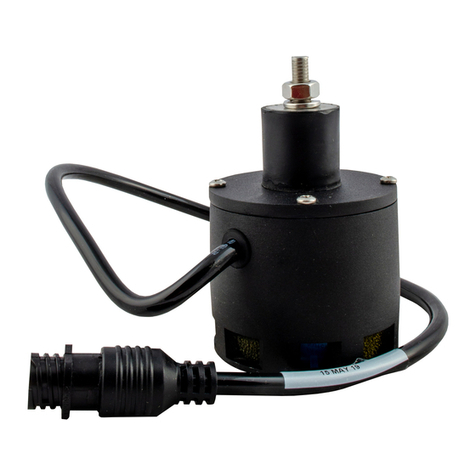
WheninstallingtheMAXSensors™(E07),startwiththesmallestserialnumberontheleft‐handsideandproceed
tothelargestserialnumberontheright‐handside.
Eachsensorhasaserialnumberstampedonthesensorhousing.
ApplyalightcoatingofthesuppliedPermatexAnti‐seizegreasetoallthreadedpartsuponinstallation.
Figure7:SensorSerialNumberArrangement

WWW.NORAC.CA
PRECISIONDEFINED
Page13
Visitwww.solutions.norac.caformoresystem
installationandtroubleshootinginfo.
6.2. BracketAssembly
1. AssemblethebreakawaysensorbracketasillustratedinFigure8.
Figure8:BreakawayBracketAssembly
2. Applyasmallamountofgreasetotherotatingsurfacesofthebracket.
Figure9:SensorBracketMounting
FRONT

WWW.NORAC.CA
PRECISIONDEFINED
Page14
Visitwww.solutions.norac.caformoresystem
installationandtroubleshootinginfo.
6.3. UltrasonicSensorMountingGuidelines
Thefollowingguidelineswillensureoptimalsensorperformanceandpreventsensormeasurementerror.These
rulesshouldbefollowedforboththewingsensorsandthemainlift(middle)sensor.
1. Initslowestposition,thesensormustbe9inches(230mm)ormorefromtheground(A).
2. Thecenterlineoftheacousticconeshouldbeapproximatelyverticalatnormaloperatingheights(A).
3. Thebottomofthesensormustbeatleast9inches(230mm)infrontofthespraynozzlesandboom
structure(B).(Thisdoesnotapplyforthemainliftsensor)
4. Thebottomofthesensormustbeatleast9inches(230mm)abovethespraynozzles(C).
5. Ensuretherearenootherobstructionswithina12inch(300mm)diametercircleprojecteddirectlybelow
thesensor(D).
Figure10:SensorMountingGuidelines
Figure11:SensorReadingOffBoom
Aproblemcanariseifasensorisnotmountedcorrectly.Itispossibleforthesensortoreadoffoftheboom
insteadoftheground.Thismayonlybecomeapparentoncethecontrolsystemisswitchedfromsoiltocrop
mode.
Alsobecarefulthatthesensorbracketdoesnotcollidewithanyotherpartoftheboomwhentheboomis
foldedtotransportposition.Ifpossible,mountthesensorbracketswhiletheboomsarefoldedtoensure
theywillnotcauseinterference.

WWW.NORAC.CA
PRECISIONDEFINED
Page15
Visitwww.solutions.norac.caformoresystem
installationandtroubleshootinginfo.
6.4. WingSensorInstallation
1. Thesensorbracketshouldbeorientedforward(aheadoftheboom).
2. Typically,thebestmountinglocationfortheouterwingsensorbracketswillbejustinsidetheboom
breakaways.
3. Mounttheinnerwingsensorsapproximatelyhalfwaybetweenthechassisandtheouterwingsensors.
4. Mountthesensorintothesensorbracket.Runthesensorcablethroughthebrackettube.
6.5. MainLiftSensorInstallation
Figure12:MainLiftBracketAssembly
1. Themainliftbracketshouldpositionthesensorapproximatelyinthecenterofthesprayer,forwardofthe
boomasshowninFigure13.
2. MounttheMAXsensortothemainliftbracket.Runthesensorcablealongthemainliftbrackettube.
Ensurethebracketdoesnotcollidewithanyotherpartofthesprayerthroughoutthefullrangeofmainlift
motion.
Figure13:MainLiftBracketMounting
MainLiftSensor

WWW.NORAC.CA
PRECISIONDEFINED
Page16
Visitwww.solutions.norac.caformoresystem
installationandtroubleshootinginfo.
7ElectronicInstallation
7.1. HCM1Installation
1. Verifythevalvecoilconnectorsareorientedvertically(Figure14).Looseningthelargeplasticnutwillallow
theconnectortoberotated.
Figure14:AlignCoils
Figure15:HCM1Connections
Figure16:HCM1Label
2. Laythelongerbranchofthevalvecables(C10)acrossthecoilswithone4‐pinconnectoroneachside.Do
notconnectthecablesatthistime.
OutputNumberNormalFunction
1,2LeftUpandDown
3,4RightUpandDown
5,6MainUpandDown
7,8RollCWandCCW

WWW.NORAC.CA
PRECISIONDEFINED
Page17
Visitwww.solutions.norac.caformoresystem
installationandtroubleshootinginfo.
Figure17:CablesUnderMountingClips(SideView)
Figure18:CablesLaidAcrossValveCoils(TopView)
3. PlacetheHCM1(E01)betweenthevalvecoils.Orientthe6‐pinDeutsch(CANbus)connectorstowardsthe
“P”and“T”portswiththelargelabelandLEDsfacingup.
4. SlidethemountingclipsovertheconnectorsoftheHCM1andthevalvecoilconnectors.Thismayrequire
flexingtheplasticbracketslightly.Ensuretheclipispushedovertheconnectorsfarenoughtoallowthe
clipstoengagebehindthevalveconnectors.
5. Connectthevalvecables(C10)tothevalvecoilsandtheHCM1.Thecableconnectedtotheleftconnector
(1,2)shouldbeconnectedtothecoilclosesttothe“P”and“T”ports.Thecableconnectedtotheright
connectorontheHCM1(3,4)shouldbeconnectedtothecoilfurthestfromthe“P”and“T”ports.
6. ConnectcableC12tothemainliftconnector(5,6)ontheHCM1.RoutecableC12underthesprayerand
teethecableintotheexistingmainliftconnections.The2‐pinDeutschconnectoractsasaboom
disconnect.
Figure19:HCM1andClipInstallation
7. Connectthetemperatureprobe(C11)totheHCM1(temp/9connector).Connectthetemperatureprobe
totheholelabelled“TP”onthevalveblockusingthesupplied3/8”x1/2”(9.5mmx25mm)bolt(Figure
20).
8. Insert4‐pinplugs(P01)intoanyunusedconnectorsontheHCM1.
Other manuals for UC7
4
Table of contents
Other Norac Control System manuals

Norac
Norac UC5 Topcon X30 User manual

Norac
Norac UC4.5 User manual

Norac
Norac UC4+ User manual

Norac
Norac UC5 Rogator 600 User manual

Norac
Norac UC5 MAX User manual

Norac
Norac UC4.5 User manual

Norac
Norac UC4.5 User manual

Norac
Norac Rogator 700 Series User manual

Norac
Norac UC5 Topcon X30 User manual

Norac
Norac UC4.5 User manual

Norac
Norac UC5 Topcon X30 User manual

Norac
Norac UC4 Total Control User manual

Norac
Norac UC4 Total Control User manual

Norac
Norac UC7 User manual

Norac
Norac UC4+ Apache 1010 2005+ User manual

Norac
Norac UC7 User manual

Norac
Norac UC4+ User manual
Norac
Norac Active Roll Control UC5 Series User manual

Norac
Norac U5 User manual
Norac
Norac UC4+ User manual