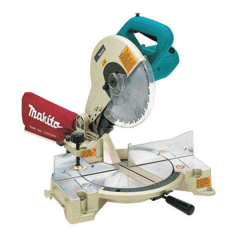
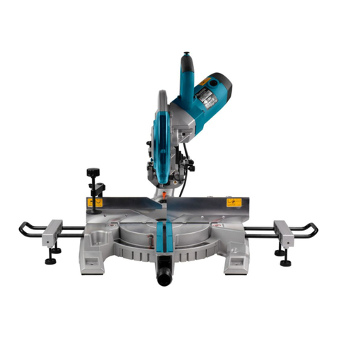
Makita LS1219 User manual

LS1219
LS1219L
EN Slide Compound Miter Saw INSTRUCTION MANUAL 15
SL Drsna sestavljena zajeralna
žaga NAVODILA ZA UPORABO 31
SQ Sharrë për prerje me kënd për
prole me rrëshqitje MANUALI I PËRDORIMIT 47
BG Настолен циркуляр с
плъзгащ се водач
РЪКОВОДСТВО ЗА
ЕКСПЛОАТАЦИЯ 65
HR Potezno-nagibna pila PRIRUČNIK S UPUTAMA 85
МК Потезна комбинирана
аголна пила УПАТСТВО ЗА УПОТРЕБА 101
SR Клизна комбинована угаона
тестера УПУТСТВО ЗА УПОТРЕБУ 120
RO Ferăstrău glisant pentru tăieri
oblice combinate MANUAL DE INSTRUCŢIUNI 138
UK Пересувна комбінована
торцювальна пила
ІНСТРУКЦІЯ З
ЕКСПЛУАТАЦІЇ 155
RU Торцовочная пила
консольного типа
РУКОВОДСТВО ПО
ЭКСПЛУАТАЦИИ 174

Fig.1
10 11
12
14
15
3
2
4
5
8
79
13
6
1
16
17
18
19
20 21
Fig.2
2

78
5
6
1
2
34
9
10
11
15
13
12
14
Fig.3
1
2
Fig.4
1
3
2
4
Fig.5
3

1
3
2
Fig.6
1
Fig.7
1
Fig.8
3
1
2
Fig.9
1
Fig.10
1
23
4
6
5
Fig.11
4

1
Fig.12
1
Fig.13
1
32
Fig.14
1
2
Fig.15
1
3
2
4
Fig.16
1
Fig.17
5

1
Fig.18
1
2
Fig.19
1
Fig.20
1
Fig.21
1
Fig.22
3
2
1
Fig.23
1
2
3
Fig.24
6

1
Fig.25
1
Fig.26
A
B
Fig.27
1
Fig.28
3
12
Fig.29
7

3
1
2
Fig.30
2
3
1
4
5
Fig.31
1
2
Fig.32
1 2 345
6
Fig.33
3
12
Fig.34
8

1
2
Fig.35
1
Fig.36
12
Fig.37
1
2
4
3
2
1
3
4
Fig.38
2
3
1
Fig.39
1
2
3
4
Fig.40
9

1
23
Fig.41
2
1
Fig.42
1
Fig.43
1
Fig.44
Fig.45
10

1
2
3
Fig.46
123
Fig.47
2
31
4
Fig.48
12
3
4
Fig.49
1
4
2
3
Fig.50
2
1
Fig.51
11

32
5
1
4
Fig.52
11
23 3
45 54
67
Fig.53
1
Fig.54
1
2
3
4
Fig.55
2
3
4
1
Fig.56
12
34
Fig.57
Fig.58
2
1
3
2
Fig.59
12

1
Fig.60
2
1
Fig.61
1
2
3
Fig.62
Fig.63
1
2
Fig.64
13

45
1
3
2
Fig.65
1
4
2
3
5
Fig.66
1
2
Fig.67
1
Fig.68
1
Fig.69
14

15 ENGLISH
ENGLISH (Original instructions)
SPECIFICATIONS
Model: LS1219 LS1219L
Blade diameter 305 mm
Hole diameter European countries 30 mm
Countries other than Europe 25.4 mm
Max. kerf thickness of the saw blade 3.2 mm
Max. miter angle Right 60°, Left 60°
Max. bevel angle Right 48°, Left 48°
No load speed (RPM) 3,200 min-1
Laser type -Red Laser 650 nm, Maximum
output
1.6mW ( Laser Class 2M )
Dimensions (L x W x H) 898 mm x 664 mm x 725 mm
Net weight 29.3 kg 29.5 kg
Safety class /II
Cutting capacities (H x W)
Miter angle Bevel angle
45° (left) 0° 45° (right)
0° -61 mm x 382 mm
71 mm x 363mm 92 mm x 382 mm
107 mm x 363 mm 44 mm x 382 mm
54 mm x 363 mm
Thickness of wood
facing on guide
fence for increased
height of cut
20 mm 78 mm × 325 mm 115 mm × 325mm 61 mm × 325 mm
38 mm 80 mm × 292 mm 120 mm × 292 mm -
45° (right and left) -61 mm x 268 mm
71 mm x 255 mm 92 mm x 268 mm
107 mm x 255 mm 44 mm x 268 mm
54 mm x 255 mm
Thickness of wood
facing on guide
fence for increased
height of cut
15 mm -115 mm × 227 mm -
25 mm 120 mm × 212 mm
60° (right and left) - - 92 mm x 185 mm
107 mm x 178 mm -
Thickness of wood
facing on guide
fence for increased
height of cut
15 mm 115 mm × 155 mm
25 mm 120 mm × 140 mm
Cutting capacities for special cuttings
Type of cutting Cutting capacity
Crown molding 45° type
(with crown molding stopper used) 203 mm
Base board
(with horizontal vise used) 171 mm
• Duetoourcontinuingprogramofresearchanddevelopment,thespecicationshereinaresubjecttochange
without notice.
• Specicationsmaydifferfromcountrytocountry.
• WeightaccordingtoEPTA-Procedure01/2014
Symbols
The following show the symbols used for the equip-
ment. Be sure that you understand their meaning before
use.
Read instruction manual.
DOUBLEINSULATION

16 ENGLISH
Toavoidinjuryfromyingdebris,keep
holding the saw head down, after making
cuts, until the blade has come to a com-
plete stop.
Whenperformingslidecut,rstpullcar-
riage fully and press down handle, then
push carriage toward the guide fence.
Donotplacehandorngersclosetothe
blade.
Never look into the laser beam. Direct laser
beammayinjureyoureyes.
Only for EU countries
Do not dispose of electric equipment
together with household waste material! In
observance of the European Directive, on
Waste Electric and Electronic Equipment
and its implementation in accordance with
national law, electric equipment that have
reached the end of their life must be col-
lected separately and returned to an envi-
ronmentally compatible recycling facility.
Intended use
The tool is intended for accurate straight and miter
cutting in wood. With appropriate saw blades, aluminum
can also be sawed.
Power supply
The tool should be connected only to a power supply of
the same voltage as indicated on the nameplate, and
canonlybeoperatedonsingle-phaseACsupply.They
are double-insulated and can, therefore, also be used
from sockets without earth wire.
Noise
ThetypicalA-weightednoiseleveldeterminedaccord-
ing to EN62841:
Model LS1219
Sound pressure level (LpA):91dB(A)
Sound power level (LWA):100dB(A)
Uncertainty(K):3dB(A)
Model LS1219L
Sound pressure level (LpA):91dB(A)
Sound power level (LWA):100dB(A)
Uncertainty(K):3dB(A)
WARNING: Wear ear protection.
Vibration
The vibration total value (tri-axial vector sum) deter-
mined according to EN62841:
Model LS1219
Vibration emission (ah) : 2.5 m/s2or less
Uncertainty (K) : 1.5 m/s2
Model LS1219L
Vibration emission (ah) : 2.5 m/s2or less
Uncertainty (K) : 1.5 m/s2
NOTE:
The declared vibration emission value has been
measured in accordance with the standard test method
and may be used for comparing one tool with another.
NOTE:
The declared vibration emission value may
also be used in a preliminary assessment of exposure.
WARNING:
The vibration emission during actual
use of the power tool can differ from the declared emission
value depending on the ways in which the tool is used.
WARNING: Be sure to identify safety measures
to protect the operator that are based on an estima-
tion of exposure in the actual conditions of use (taking
account of all parts of the operating cycle such as
the times when the tool is switched off and when it is
running idle in addition to the trigger time).
EC Declaration of Conformity
For European countries only
TheECdeclarationofconformityisincludedasAnnexA
to this instruction manual.
SAFETY WARNINGS
General power tool safety warnings
WARNING: Read all safety warnings, instruc-
tions, illustrations and specications provided
with this power tool. Failure to follow all instructions
listedbelowmayresultinelectricshock,reand/or
seriousinjury.
Save all warnings and instruc-
tions for future reference.
The term "power tool" in the warnings refers to your
mains-operated (corded) power tool or battery-operated
(cordless) power tool.
Safety instructions for mitre saws
1. Mitre saws are intended to cut wood or wood-
like products, they cannot be used with abra-
sive cut-off wheels for cutting ferrous material
such as bars, rods, studs, etc.Abrasivedust
causes moving parts such as the lower guard to
jam.Sparksfromabrasivecuttingwillburnthe
lower guard, the kerf insert and other plastic parts.
2.
Use clamps to support the workpiece whenever
possible. If supporting the workpiece by hand,
you must always keep your hand at least 100
mm from either side of the saw blade. Do not
use this saw to cut pieces that are too small to
be securely clamped or held by hand. If your
hand is placed too close to the saw blade, there is
anincreasedriskofinjuryfrombladecontact.
3. The workpiece must be stationary and
clamped or held against both the fence and the
table. Do not feed the workpiece into the blade
or cut "freehand" in any way. Unrestrained
or moving workpieces could be thrown at high
speeds,causinginjury.

17 ENGLISH
4. Push the saw through the workpiece. Do not
pull the saw through the workpiece. To make
a cut, raise the saw head and pull it out over
the workpiece without cutting, start the motor,
press the saw head down and push the saw
through the workpiece. Cutting on the pull stroke
is likely to cause the saw blade to climb on top
of the workpiece and violently throw the blade
assembly towards the operator.
5.
Never cross your hand over the intended line of
cutting either in front or behind the saw blade.
Supporting the workpiece "cross handed" i.e. hold-
ing the workpiece to the right of the saw blade with
your left hand or vice versa is very dangerous.
►Fig.1
6. Do not reach behind the fence with either hand
closer than 100 mm from either side of the saw
blade, to remove wood scraps, or for any other
reason while the blade is spinning. The proxim-
ity of the spinning saw blade to your hand may not
beobviousandyoumaybeseriouslyinjured.
7. Inspect your workpiece before cutting. If the
workpiece is bowed or warped, clamp it with
the outside bowed face toward the fence.
Always make certain that there is no gap
between the workpiece, fence and table along
the line of the cut. Bent or warped workpieces
can twist or shift and may cause binding on the
spinning saw blade while cutting. There should be
nonailsorforeignobjectsintheworkpiece.
8. Do not use the saw until the table is clear of all
tools, wood scraps, etc., except for the work-
piece. Small debris or loose pieces of wood or
otherobjectsthatcontacttherevolvingbladecan
be thrown with high speed.
9. Cut only one workpiece at a time. Stacked multi-
ple workpieces cannot be adequately clamped or
braced and may bind on the blade or shift during
cutting.
10. Ensure the mitre saw is mounted or placed on
a level, rm work surface before use. Alevel
andrmworksurfacereducestheriskofthemitre
saw becoming unstable.
11. Plan your work. Every time you change the
bevel or mitre angle setting, make sure the
adjustable fence is set correctly to support the
workpiece and will not interfere with the blade
or the guarding system. Without turning the tool
"ON" and with no workpiece on the table, move
the saw blade through a complete simulated cut to
assure there will be no interference or danger of
cutting the fence.
12. Provide adequate support such as table exten-
sions, saw horses, etc. for a workpiece that is
wider or longer than the table top. Workpieces
longer or wider than the mitre saw table can tip
if not securely supported. If the cut-off piece or
workpiece tips, it can lift the lower guard or be
thrown by the spinning blade.
13. Do not use another person as a substitute for
a table extension or as additional support.
Unstable support for the workpiece can cause the
blade to bind or the workpiece to shift during the
cutting operation pulling you and the helper into
the spinning blade.
14. The cut-off piece must not be jammed or
pressed by any means against the spinning
saw blade.Ifconned,i.e.usinglengthstops,the
cut-off piece could get wedged against the blade
and thrown violently.
15. Always use a clamp or a xture designed to
properly support round material such as rods
or tubing. Rods have a tendency to roll while
being cut, causing the blade to "bite" and pull the
work with your hand into the blade.
16. Let the blade reach full speed before contact-
ing the workpiece. This will reduce the risk of the
workpiece being thrown.
17. If the workpiece or blade becomes jammed,
turn the mitre saw off. Wait for all moving
parts to stop and disconnect the plug from
the power source and/or remove the battery
pack. Then work to free the jammed material.
Continuedsawingwithajammedworkpiececould
cause loss of control or damage to the mitre saw.
18. After nishing the cut, release the switch,
hold the saw head down and wait for the blade
to stop before removing the cut-off piece.
Reaching with your hand near the coasting blade
is dangerous.
19. Hold the handle rmly when making an incom-
plete cut or when releasing the switch before
the saw head is completely in the down posi-
tion. The braking action of the saw may cause
the saw head to be suddenly pulled downward,
causingariskofinjury.
20. Only use the saw blade with the diameter that
is marked on the tool or specied in the man-
ual. Use of an incorrectly sized blade may affect
the proper guarding of the blade or guard opera-
tionwhichcouldresultinseriouspersonalinjury.
21. Only use the saw blades that are marked with
a speed equal or higher than the speed marked
on the tool.
22. Do not use the saw to cut other than wood,
aluminum or similar materials.
23. (For European countries only)
Always use the blade which conforms to
EN847-1.
Additional instructions
1. Make workshop kid proof with padlocks.
2. Never stand on the tool.Seriousinjurycould
occur if the tool is tipped or if the cutting tool is
unintentionally contacted.
3. Never leave the tool running unattended. Turn
the power off. Do not leave tool until it comes
to a complete stop.
4. Do not operate saw without guards in place.
Check blade guard for proper closing before
each use. Do not operate saw if blade guard
does not move freely and close instantly.
Never clamp or tie the blade guard into the
open position.
5. Keep hands out of path of saw blade. Avoid
contact with any coasting blade. It can still
cause severe injury.
6. To reduce the risk of injury, return carriage
to the full rear position after each crosscut
operation.

18 ENGLISH
7. Always secure all moving portions before
carrying the tool.
8. Stopper pin which locks the cutter head down
is for carrying and storage purposes only and
not for any cutting operations.
9. Check the blade carefully for cracks or dam-
age before operation. Replace cracked or dam-
aged blade immediately. Gum and wood pitch
hardened on blades slows saw and increases
potential for kickback. Keep blade clean by
rst removing it from tool, then cleaning it with
gum and pitch remover, hot water or kerosene.
Never use gasoline to clean blade.
10. While making a slide cut, KICKBACK can
occur. KICKBACK occurs when the blade
binds in the workpiece during a cutting oper-
ation and the saw blade is driven rapidly
towards the operator. Loss of control and seri-
ous personal injury can result. If blade begins
to bind during a cutting operation, do not con-
tinue to cut and release switch immediately.
11. Use only anges specied for this tool.
12. Be careful not to damage the arbor, anges
(especially the installing surface) or bolt.
Damage to these parts could result in blade
breakage.
13. Make sure that the turn base is properly
secured so it will not move during operation.
Use the holes in the base to fasten the saw to a
stable work platform or bench. NEVER use tool
where operator positioning would be awkward.
14. Make sure the shaft lock is released before the
switch is turned on.
15. Be sure that the blade does not contact the
turn base in the lowest position.
16. Hold the handle rmly. Be aware that the saw
moves up or down slightly during start-up and
stopping.
17. Make sure the blade is not contacting the
workpiece before the switch is turned on.
18. Before using the tool on an actual workpiece,
let it run for a while. Watch for vibration or
wobbling that could indicate poor installation
or a poorly balanced blade.
19. Stop operation immediately if you notice any-
thing abnormal.
20. Do not attempt to lock the trigger in the "ON"
position.
21. Always use accessories recommended in this
manual. Use of improper accessories such as
abrasive wheels may cause an injury.
22. Some material contains chemicals which may
be toxic. Take caution to prevent dust inhala-
tion and skin contact. Follow material supplier
safety data.
Additional safety rules for the laser
1. LASER RADIATION, DO NOT STARE INTO THE
BEAM OR VIEW DIRECTLY WITH OPTICAL
INSTRUMENTS, CLASS 2M LASER PRODUCT.
SAVE THESE INSTRUCTIONS.
WARNING: DO NOT let comfort or familiarity
with product (gained from repeated use) replace
strict adherence to safety rules for the subject
product. MISUSE or failure to follow the safety
rules stated in this instruction manual may cause
serious personal injury.
PARTS DESCRIPTION
►Fig.2
1Slide pole 2Stopper pin (for carriage
sliding) 3Vertical vise 4Releasing button (for
right side bevel angle)
5Holder 6Turn base 7Pointer (for miter angle) 8Miter angle scale
9Kerf board 10 Blade case 11 Adjustingscrew(for
laser line) 12 Rangeadjustmentscrew
(for laser line)
13 Blade guard 14 Knob (for bevel angle) 15 Hex wrench 16 Adjustingscrew(for
lower limit position)
17 Adjustingbolt(formaxi-
mum cutting capacity) 18 Stopper arm 19 Lock lever (for turn base) 20 Releasing lever (for turn
base)
21 Grip (for turn base) ------
►Fig.3
1Switch trigger 2Lock-off button 3Hole for padlock 4Switch (for laser line)
5Hose (for dust
extraction) 6Stopper pin (for carriage
elevation) 7Guide fence (lower
fence) 8Guide fence (upper
fence)
9Dust bag 10 0°adjustingbolt(for
bevel angle) 11 Bevel angle scale 12 Releasing lever (for 48°
bevel angle)
13 Latch lever (for bevel
angle) 14 Pointer (for bevel angle) 15 45°adjustingbolt(for
bevel angle) - -

19 ENGLISH
INSTALLATION
Installing the grip
Screw the threaded shaft of the grip into the turn base.
►Fig.4: 1. Grip 2. Turn base
Installing the dust extraction hose
Connect the dust extraction hose to the tool as
illustrated.
Makesurethattheelbowandthesleevetproperlyto
the ports of the tool.
►Fig.5: 1. Dust extraction hose 2. Elbow 3. Sleeve
4. Port
Bench mounting
When the tool is shipped, the handle is locked in the
lowered position by the stopper pin. While lowering the
handle slightly, pull the stopper pin and rotate it 90°.
►Fig.6: 1. Locked position 2. Unlocked position
3. Stopper pin
This tool should be bolted with four bolts to a level and
stable surface using the bolt holes provided in the tool's
base.Thiswillhelppreventtippingandpossibleinjury.
►Fig.7: 1. Bolt
WARNING: Ensure that the tool will not move
on the supporting surface. Movement of the miter
saw on the supporting surface while cutting may
resultinlossofcontrolandseriouspersonalinjury.
FUNCTIONAL
DESCRIPTION
WARNING: Always be sure that the tool is
switched off and unplugged before adjusting or
checking function on the tool. Failure to switch off
and unplug the tool may result in serious personal
injuryfromaccidentalstart-up.
Blade guard
►Fig.8: 1. Blade guard
When lowering the handle, the blade guard rises auto-
matically. The guard is spring loaded so it returns to
its original position when the cut is completed and the
handle is raised.
WARNING: Never defeat or remove the blade
guard or the spring which attaches to the guard.
Anexposedbladeasaresultofdefeatedguarding
mayresultinseriouspersonalinjuryduringoperation.
In the interest of your personal safety, always maintain
thebladeguardingoodcondition.Anyirregularopera-
tion of the blade guard should be corrected immediately.
Check to assure spring loaded return action of guard.
WARNING: Never use the tool if the blade
guard or spring are damaged, faulty or removed.
Operation of the tool with a damaged, faulty or
removedguardmayresultinseriouspersonalinjury.
If the see-through blade guard becomes dirty, or saw-
dust adheres to it in such a way that the blade and/or
workpiece is no longer easily visible, unplug the saw and
clean the guard carefully with a damp cloth. Do not use
solvents or any petroleum-based cleaners on the plastic
guard because this may cause damage to the guard.
If the blade guard is especially dirty and vision through
the guard is impaired, unplug the tool and use the sup-
plied wrench to loosen the hex bolt holding the center
cover. Loosen the hex bolt by turning it counterclock-
wise and raise the blade guard and center cover. With
the blade guard so positioned, cleaning can be more
completelyandefcientlyaccomplished.Whencleaning
is complete, reverse procedure above and secure bolt.
Do not remove spring holding blade guard. If guard
becomes discolored through age or UV light exposure,
contact a Makita service center for a new guard. DO
NOTDEFEATORREMOVEGUARD.
►Fig.9: 1. Center cover 2. Hex wrench 3. Blade
guard
Kerf boards
This tool is provided with the kerf boards in the turn
base to minimize tearing on the exit side of a cut. The
kerfboardsarefactoryadjustedsothatthesawblade
doesnotcontactthekerfboards.Beforeuse,adjustthe
kerf boards as follows:
►Fig.10: 1. Kerf board
►Fig.11: 1. Left bevel cut 2. Straight cut 3. Right
bevel cut 4. Saw blade 5. Blade teeth
6. Kerf board

20 ENGLISH
First, unplug the tool. Loosen all the screws (2 each
on left and right) securing the kerf boards until the kerf
boards can still be easily moved by hand. Lower the
handle fully, then pull and turn the stopper pin to lock
the handle in the lowered position. Release the stopper
pin on the sliding pole and pull the carriage toward you
fully.Adjustthekerfboardssothatthekerfboardsjust
contact the sides of the blade teeth. Tighten the front
screws(donottightenrmly).Pushthecarriagetoward
theguidefencefullyandadjustthekerfboardssothat
thekerfboardsjustcontactthesidesofbladeteeth.
Tightentherearscrews(donottightenrmly).
Afteradjustingthekerfboards,releasethestopper
pin and raise the handle. Then tighten all the screws
securely.
NOTICE: After setting the bevel angle ensure
that the kerf boards are adjusted properly. Correct
adjustmentofthekerfboardswillhelpprovideproper
support of the workpiece minimizing workpiece tear
out.
Maintaining maximum cutting
capacity
Thistoolisfactoryadjustedtoprovidethemaximum
cutting capacity for a 305 mm saw blade.
When installing a new blade, always check the lower
limitpositionofthebladeandifnecessary,adjustitas
follows:
First, unplug the tool. Turn the stopper lever to engaged
position.
►Fig.12: 1. Stopper lever
Push the carriage toward the guide fence fully and
lower the handle completely.
Adjustthebladepositionbyturningtheadjustingbolt
with the hex wrench. The periphery of the blade should
extend slightly below the top surface of the turn base
and also comes to the point where the front face of the
guide fence meets the top surface of the turn base.
►Fig.13: 1.Adjustingbolt
►Fig.14: 1. Top surface of turn base 2. Periphery of
blade 3. Guide fence
With the tool unplugged, rotate the blade by hand while
holding the handle all the way down to be sure that
the blade does not contact any part of the lower base.
Re-adjustslightly,ifnecessary.
Afteradjustment,alwaysreturnthestopperlevertothe
original position.
WARNING: After installing a new blade and
with the tool unplugged, always be sure that the
blade does not contact any part of the lower base
when the handle is lowered completely. If a blade
makes contact with the base it may cause kickback
andresultinseriouspersonalinjury.
Stopper arm
The lower limit position of the blade can be easily
adjustedwiththestopperarm.Toadjustit,turnthe
stopper arm in the direction of the arrow as shown in the
gure.Turntheadjustingscrewsothatthebladestops
at the desired position when lowering the handle fully.
►Fig.15: 1. Stopper arm 2.Adjustingscrew
Adjusting the miter angle
CAUTION: After changing the miter angle,
always secure the turn base by tightening the grip
rmly.
NOTICE: When turning the turn base, be sure to
raise the handle fully.
►Fig.16: 1. Lock lever 2. Grip 3. Releasing lever
4. Pointer
Rotate the grip counterclockwise to unlock the turn
base. Turn the grip while holding down the lock lever to
movetheturnbase.Alignthepointerwithyourdesired
angle on the scale then tighten the grip.
NOTE: If you depress the releasing lever, you can
move the turn base without holding down the lock
lever. Tighten the grip at your desired position.
This miter saw employs positive stop function. You can
set 0°, 15°, 22.5°, 31.6°, 45°, and 60° right/left miter
angle quickly. To use this function, move the turn base
close to your desired positive stop angle while holding
down the lock lever. Then release the lock lever and
move the turn base forward until the turn base is locked.
Adjusting the bevel angle
NOTICE: Always remove the upper guide fences
and vertical vise before adjusting the bevel angle.
NOTICE: When changing bevel angles, be sure
to position the kerf boards appropriately as
explained in the "Kerf boards" section.
NOTICE: When tilting the saw blade, be sure to
raise the handle fully.
NOTICE: Do not tighten the knob too hard. Doing
so may cause malfunction of the locking mecha-
nism of the bevel angle.
1. Turn the knob on the slide pole counterclockwise.
►Fig.17: 1. Knob
2. Pull and turn the latch lever to the position as
illustrated.
►Fig.18: 1. Latch lever
3. Match the pointer with your desired angle on the
scale by moving the carriage then tighten the knob.
►Fig.19: 1. Bevel angle scale 2. Pointer
To tilt the carriage to the right, tilt the carriage to the left
slightly and then tilt it to the right while pressing down
the releasing button.
►Fig.20: 1. Releasing button
If you perform a bevel cut greater than 45°, move the
carriage while sliding the releasing lever toward the
front of the tool. You can perform up to 48° bevel cut.
►Fig.21: 1. Releasing lever
This miter saw employs positive stop function. You can
set 22.5° and 33.9° angle to both right and left quickly.
Set the latch lever in the position as illustrated and tilt
the carriage. To change the angle, pull the latch lever
and tilt the carriage.
►Fig.22: 1. Latch lever
Other manuals for LS1219
5
This manual suits for next models
1
Table of contents
Languages:
Other Makita Saw manuals

Makita
Makita DLS211 User manual

Makita
Makita 5008MG User manual

Makita
Makita DLS713 User manual

Makita
Makita 5008MGJ User manual

Makita
Makita LH1040 User manual

Makita
Makita LF1000 User manual

Makita
Makita GSH05 User manual

Makita
Makita DLS714 User manual

Makita
Makita 2107F User manual

Makita
Makita DPC6430 Instruction Manual

Makita
Makita BLS820SFK Quick start guide

Makita
Makita DSS610Z User manual

Makita
Makita 5008MG User manual

Makita
Makita EK7650H User guide

Makita
Makita 5704R Manual

Makita
Makita LS800D User manual

Makita
Makita LS0815F User manual

Makita
Makita 5377MG Quick start guide

Makita
Makita JR100D User manual

Makita
Makita LS0714F User manual