manuals.online logo
Brands
  1. Home
  2. •
  3. Brands
  4. •
  5. Challenger
  6. •
  7. Farm Equipment
  8. •
  9. Challenger 648 D User manual

Challenger 648 D User manual

This manual suits for next models

3

Other Challenger Farm Equipment manuals

Challenger RG900B User manual

Challenger

Challenger RG900B User manual

Challenger TG8400C User manual

Challenger

Challenger TG8400C User manual

Challenger RG900C User manual

Challenger

Challenger RG900C User manual

Challenger 660B User manual

Challenger

Challenger 660B User manual

Challenger TG8400B User manual

Challenger

Challenger TG8400B User manual

Popular Farm Equipment manuals by other brands

Schaffert Rebounder Mounting instructions

Schaffert

Schaffert Rebounder Mounting instructions

Stocks AG Fan Jet Pro Plus 65 Original Operating Manual and parts list

Stocks AG

Stocks AG Fan Jet Pro Plus 65 Original Operating Manual and parts list

Cumberland Integra Feed-Link Installation and operation manual

Cumberland

Cumberland Integra Feed-Link Installation and operation manual

BROWN BDHP-1250 Owner's/operator's manual

BROWN

BROWN BDHP-1250 Owner's/operator's manual

Molon BCS operating instructions

Molon

Molon BCS operating instructions

Vaderstad Rapid Series instructions

Vaderstad

Vaderstad Rapid Series instructions

HighLine BM1400 operating manual

HighLine

HighLine BM1400 operating manual

GSi PNEG-2314 installation manual

GSi

GSi PNEG-2314 installation manual

Checchi & Magli TEXDRIVE owner's manual

Checchi & Magli

Checchi & Magli TEXDRIVE owner's manual

Amazone Cenius 4003-2TX operating manual

Amazone

Amazone Cenius 4003-2TX operating manual

MASSEY FERGUSON MF 9313S Operator's manual

MASSEY FERGUSON

MASSEY FERGUSON MF 9313S Operator's manual

Cima BLITZ Maintenance Instruction

Cima

Cima BLITZ Maintenance Instruction

Amazone CombiDisc 3000 Original operating manual

Amazone

Amazone CombiDisc 3000 Original operating manual

HE-VA Disc-Roller XL Contour Operating instructions/spare parts list

HE-VA

HE-VA Disc-Roller XL Contour Operating instructions/spare parts list

AGT AGT-SSFM product manual

AGT

AGT AGT-SSFM product manual

Milestone 72-84 manual

Milestone

Milestone 72-84 manual

KUHN Hector 3000 Complementary instructions

KUHN

KUHN Hector 3000 Complementary instructions

Krone X-Disc 6200 operating instructions

Krone

Krone X-Disc 6200 operating instructions

manuals.online logo
manuals.online logoBrands
  • About & Mission
  • Contact us
  • Privacy Policy
  • Terms and Conditions

Copyright 2025 Manuals.Online. All Rights Reserved.

648 D
from serial no. 553900084
652 D
from serial no. 564000301
ORIGINAL
OPERATOR'S
MANUAL
TABLE OF CONTENTS
1. General Information
2. Operation
3. Controls and Instruments
4. Field Operations
5. Lubrication and Maintenance
6. Adjustments
7. Systems
8. Troubleshooting
9. Off-Season Storage
10. Optional Equipment
11. Technical Specifications
12. Alphabetical Index
Find manuals at http://best-manuals.com/search?&s=CHAl-LA327318013.PDF
CONTENTS
Section-page
1
1. GENERAL INFORMATION
Customer information . . . . . . . . . . . . . . . . . . . . . . . . . . . . . . . . . . . . . . . . . . . . . . . . . . . . . . . . . . . 1-1
Appropriate use . . . . . . . . . . . . . . . . . . . . . . . . . . . . . . . . . . . . . . . . . . . . . . . . . . . . . . . . . . . . . . . . 1-3
Combine identification . . . . . . . . . . . . . . . . . . . . . . . . . . . . . . . . . . . . . . . . . . . . . . . . . . . . . . . . . . .1-4
Ecology: information for the prevention of environmental pollution . . . . . . . . . . . . . . . . . . . . . . . .1-9
Safety . . . . . . . . . . . . . . . . . . . . . . . . . . . . . . . . . . . . . . . . . . . . . . . . . . . . . . . . . . . . . . . . . . . . . . . 1-10
Emergency exit . . . . . . . . . . . . . . . . . . . . . . . . . . . . . . . . . . . . . . . . . . . . . . . . . . . . . . . . . . . . . . .1-33
Safety devices . . . . . . . . . . . . . . . . . . . . . . . . . . . . . . . . . . . . . . . . . . . . . . . . . . . . . . . . . . . . . . . .1-34
Machine lifting . . . . . . . . . . . . . . . . . . . . . . . . . . . . . . . . . . . . . . . . . . . . . . . . . . . . . . . . . . . . . . . .1-44
Towing the combine . . . . . . . . . . . . . . . . . . . . . . . . . . . . . . . . . . . . . . . . . . . . . . . . . . . . . . . . . . .1-45
Fire resistance inside the cab . . . . . . . . . . . . . . . . . . . . . . . . . . . . . . . . . . . . . . . . . . . . . . . . . . . .1-45
Noise level in the cab . . . . . . . . . . . . . . . . . . . . . . . . . . . . . . . . . . . . . . . . . . . . . . . . . . . . . . . . . . .1-46
Ambient noise in motion Directive 2009/63/EC . . . . . . . . . . . . . . . . . . . . . . . . . . . . . . . . . . . . . . .1-46
Vibrations in the cab . . . . . . . . . . . . . . . . . . . . . . . . . . . . . . . . . . . . . . . . . . . . . . . . . . . . . . . . . . .1-46
Statutory regulations . . . . . . . . . . . . . . . . . . . . . . . . . . . . . . . . . . . . . . . . . . . . . . . . . . . . . . . . . . . 1-47
Hydraulic systems: hoses . . . . . . . . . . . . . . . . . . . . . . . . . . . . . . . . . . . . . . . . . . . . . . . . . . . . . . . 1-47
Scrapping and disposal . . . . . . . . . . . . . . . . . . . . . . . . . . . . . . . . . . . . . . . . . . . . . . . . . . . . . . . . . 1-48
Electromagnetic emissions . . . . . . . . . . . . . . . . . . . . . . . . . . . . . . . . . . . . . . . . . . . . . . . . . . . . . . 1-48
Notes for road transport . . . . . . . . . . . . . . . . . . . . . . . . . . . . . . . . . . . . . . . . . . . . . . . . . . . . . . . .1-49
Weight distribution . . . . . . . . . . . . . . . . . . . . . . . . . . . . . . . . . . . . . . . . . . . . . . . . . . . . . . . . . . . . .1-51
2. OPERATION
Crop processing . . . . . . . . . . . . . . . . . . . . . . . . . . . . . . . . . . . . . . . . . . . . . . . . . . . . . . . . . . . . . . . 2-1
3. CONTROLS AND INSTRUMENTS
Steering column . . . . . . . . . . . . . . . . . . . . . . . . . . . . . . . . . . . . . . . . . . . . . . . . . . . . . . . . . . . . . . . . 3-1
Service and parking brakes . . . . . . . . . . . . . . . . . . . . . . . . . . . . . . . . . . . . . . . . . . . . . . . . . . . . . . .3-3
Multifunction lever . . . . . . . . . . . . . . . . . . . . . . . . . . . . . . . . . . . . . . . . . . . . . . . . . . . . . . . . . . . . . . 3-4
Gearshift lever and reversing lever . . . . . . . . . . . . . . . . . . . . . . . . . . . . . . . . . . . . . . . . . . . . . . . . .3-6
Control panel (models 648 D and 652 D) . . . . . . . . . . . . . . . . . . . . . . . . . . . . . . . . . . . . . . . . . . . .3-7
Computer . . . . . . . . . . . . . . . . . . . . . . . . . . . . . . . . . . . . . . . . . . . . . . . . . . . . . . . . . . . . . . . . . . . . 3-11
Cab . . . . . . . . . . . . . . . . . . . . . . . . . . . . . . . . . . . . . . . . . . . . . . . . . . . . . . . . . . . . . . . . . . . . . . . .3-39
Access to combine components . . . . . . . . . . . . . . . . . . . . . . . . . . . . . . . . . . . . . . . . . . . . . . . . . .3-50
Starting the engine . . . . . . . . . . . . . . . . . . . . . . . . . . . . . . . . . . . . . . . . . . . . . . . . . . . . . . . . . . . .3-54
Stopping the engine . . . . . . . . . . . . . . . . . . . . . . . . . . . . . . . . . . . . . . . . . . . . . . . . . . . . . . . . . . . 3-55
Operations to be carried out before road transport . . . . . . . . . . . . . . . . . . . . . . . . . . . . . . . . . . .3-56
Before using the combine . . . . . . . . . . . . . . . . . . . . . . . . . . . . . . . . . . . . . . . . . . . . . . . . . . . . . . .3-58
4. FIELD OPERATIONS
General Information . . . . . . . . . . . . . . . . . . . . . . . . . . . . . . . . . . . . . . . . . . . . . . . . . . . . . . . . . . . . . 4-1
Starting and Stopping the Combine . . . . . . . . . . . . . . . . . . . . . . . . . . . . . . . . . . . . . . . . . . . . . . . . 4-2
Cutting table . . . . . . . . . . . . . . . . . . . . . . . . . . . . . . . . . . . . . . . . . . . . . . . . . . . . . . . . . . . . . . . . . . 4-4
Main Crop Elevator . . . . . . . . . . . . . . . . . . . . . . . . . . . . . . . . . . . . . . . . . . . . . . . . . . . . . . . . . . . . . 4-9
Cylinder Housing . . . . . . . . . . . . . . . . . . . . . . . . . . . . . . . . . . . . . . . . . . . . . . . . . . . . . . . . . . . . . . 4-13
Concave . . . . . . . . . . . . . . . . . . . . . . . . . . . . . . . . . . . . . . . . . . . . . . . . . . . . . . . . . . . . . . . . . . . . .4-14
Rear beater . . . . . . . . . . . . . . . . . . . . . . . . . . . . . . . . . . . . . . . . . . . . . . . . . . . . . . . . . . . . . . . . . .4-19
Multi Crop Separator . . . . . . . . . . . . . . . . . . . . . . . . . . . . . . . . . . . . . . . . . . . . . . . . . . . . . . . . . . . 4-20
Straw walkers . . . . . . . . . . . . . . . . . . . . . . . . . . . . . . . . . . . . . . . . . . . . . . . . . . . . . . . . . . . . . . . .4-23
Main Grain Pan . . . . . . . . . . . . . . . . . . . . . . . . . . . . . . . . . . . . . . . . . . . . . . . . . . . . . . . . . . . . . . .4-24
Fanning mill . . . . . . . . . . . . . . . . . . . . . . . . . . . . . . . . . . . . . . . . . . . . . . . . . . . . . . . . . . . . . . . . . .4-27
Top sieve . . . . . . . . . . . . . . . . . . . . . . . . . . . . . . . . . . . . . . . . . . . . . . . . . . . . . . . . . . . . . . . . . . . . 4-28
Bottom sieve . . . . . . . . . . . . . . . . . . . . . . . . . . . . . . . . . . . . . . . . . . . . . . . . . . . . . . . . . . . . . . . . . 4-29
Returns . . . . . . . . . . . . . . . . . . . . . . . . . . . . . . . . . . . . . . . . . . . . . . . . . . . . . . . . . . . . . . . . . . . . .4-30
Grain tank . . . . . . . . . . . . . . . . . . . . . . . . . . . . . . . . . . . . . . . . . . . . . . . . . . . . . . . . . . . . . . . . . . .4-31
Find manuals at http://best-manuals.com/search?&s=CHAl-LA327318013.PDF
CONTENTS
Section-page
2
5. LUBRICATION AND MAINTENANCE
General information . . . . . . . . . . . . . . . . . . . . . . . . . . . . . . . . . . . . . . . . . . . . . . . . . . . . . . . . . . . . . 5-1
Preliminary Service Inspection . . . . . . . . . . . . . . . . . . . . . . . . . . . . . . . . . . . . . . . . . . . . . . . . . . . .5-2
Scheduled Service Inspection . . . . . . . . . . . . . . . . . . . . . . . . . . . . . . . . . . . . . . . . . . . . . . . . . . . . . 5-3
Where and When to Carry Out Service Inspection . . . . . . . . . . . . . . . . . . . . . . . . . . . . . . . . . . . . . 5-4
Periodical maintenance operations . . . . . . . . . . . . . . . . . . . . . . . . . . . . . . . . . . . . . . . . . . . . . . . .5-39
Capacities and specifications 648 D . . . . . . . . . . . . . . . . . . . . . . . . . . . . . . . . . . . . . . . . . . . . . . .5-42
Capacities and specifications 652 D . . . . . . . . . . . . . . . . . . . . . . . . . . . . . . . . . . . . . . . . . . . . . . .5-43
6. ADJUSTMENTS
Belt and chain adjustment . . . . . . . . . . . . . . . . . . . . . . . . . . . . . . . . . . . . . . . . . . . . . . . . . . . . . . . .6-1
Belts and chains (left-hand side) . . . . . . . . . . . . . . . . . . . . . . . . . . . . . . . . . . . . . . . . . . . . . . . . . . .6-2
Belts and chains (right-hand side) . . . . . . . . . . . . . . . . . . . . . . . . . . . . . . . . . . . . . . . . . . . . . . . . . 6-11
Reverse drive system . . . . . . . . . . . . . . . . . . . . . . . . . . . . . . . . . . . . . . . . . . . . . . . . . . . . . . . . . .6-17
Slip clutches . . . . . . . . . . . . . . . . . . . . . . . . . . . . . . . . . . . . . . . . . . . . . . . . . . . . . . . . . . . . . . . . . 6-19
Unloading tube . . . . . . . . . . . . . . . . . . . . . . . . . . . . . . . . . . . . . . . . . . . . . . . . . . . . . . . . . . . . . . .6-20
Tyres . . . . . . . . . . . . . . . . . . . . . . . . . . . . . . . . . . . . . . . . . . . . . . . . . . . . . . . . . . . . . . . . . . . . . . . 6-21
Brakes . . . . . . . . . . . . . . . . . . . . . . . . . . . . . . . . . . . . . . . . . . . . . . . . . . . . . . . . . . . . . . . . . . . . . . 6-25
Rear axle . . . . . . . . . . . . . . . . . . . . . . . . . . . . . . . . . . . . . . . . . . . . . . . . . . . . . . . . . . . . . . . . . . . .6-27
Battery . . . . . . . . . . . . . . . . . . . . . . . . . . . . . . . . . . . . . . . . . . . . . . . . . . . . . . . . . . . . . . . . . . . . . .6-31
7. SYSTEMS
Engine supply system . . . . . . . . . . . . . . . . . . . . . . . . . . . . . . . . . . . . . . . . . . . . . . . . . . . . . . . . . . . 7-2
Engine air intake and exhaust system . . . . . . . . . . . . . . . . . . . . . . . . . . . . . . . . . . . . . . . . . . . . . . . 7-5
Engine cooling system . . . . . . . . . . . . . . . . . . . . . . . . . . . . . . . . . . . . . . . . . . . . . . . . . . . . . . . . . . . 7-6
Engine lubrication system . . . . . . . . . . . . . . . . . . . . . . . . . . . . . . . . . . . . . . . . . . . . . . . . . . . . . . . . 7-8
SCR system . . . . . . . . . . . . . . . . . . . . . . . . . . . . . . . . . . . . . . . . . . . . . . . . . . . . . . . . . . . . . . . . . . . 7-9
Hydraulics system . . . . . . . . . . . . . . . . . . . . . . . . . . . . . . . . . . . . . . . . . . . . . . . . . . . . . . . . . . . . . 7-11
Hydrostatic transmission system . . . . . . . . . . . . . . . . . . . . . . . . . . . . . . . . . . . . . . . . . . . . . . . . . 7-17
Electrical system . . . . . . . . . . . . . . . . . . . . . . . . . . . . . . . . . . . . . . . . . . . . . . . . . . . . . . . . . . . . . .7-19
8. TROUBLESHOOTING
Feeding . . . . . . . . . . . . . . . . . . . . . . . . . . . . . . . . . . . . . . . . . . . . . . . . . . . . . . . . . . . . . . . . . . . . . . 8-1
Threshing . . . . . . . . . . . . . . . . . . . . . . . . . . . . . . . . . . . . . . . . . . . . . . . . . . . . . . . . . . . . . . . . . . . . . 8-1
Separation and cleaning . . . . . . . . . . . . . . . . . . . . . . . . . . . . . . . . . . . . . . . . . . . . . . . . . . . . . . . . . 8-3
Hydrostatic Transmission . . . . . . . . . . . . . . . . . . . . . . . . . . . . . . . . . . . . . . . . . . . . . . . . . . . . . . . . 8-5
Engine . . . . . . . . . . . . . . . . . . . . . . . . . . . . . . . . . . . . . . . . . . . . . . . . . . . . . . . . . . . . . . . . . . . . . . .8-6
Hydraulics system . . . . . . . . . . . . . . . . . . . . . . . . . . . . . . . . . . . . . . . . . . . . . . . . . . . . . . . . . . . . . 8-16
Levelling Hydraulics System . . . . . . . . . . . . . . . . . . . . . . . . . . . . . . . . . . . . . . . . . . . . . . . . . . . . .8-16
Electrical System . . . . . . . . . . . . . . . . . . . . . . . . . . . . . . . . . . . . . . . . . . . . . . . . . . . . . . . . . . . . . .8-17
Air conditioning circuit . . . . . . . . . . . . . . . . . . . . . . . . . . . . . . . . . . . . . . . . . . . . . . . . . . . . . . . . . .8-17
Straw Chopper . . . . . . . . . . . . . . . . . . . . . . . . . . . . . . . . . . . . . . . . . . . . . . . . . . . . . . . . . . . . . . .8-19
9. OFF-SEASON
9. STORAGE
10. OPTIONAL EQUIPMENT
11. TECHNICAL SPECIFICATIONS
Wheels and tyres . . . . . . . . . . . . . . . . . . . . . . . . . . . . . . . . . . . . . . . . . . . . . . . . . . . . . . . . . . . . . .11-1
Combine dimensions . . . . . . . . . . . . . . . . . . . . . . . . . . . . . . . . . . . . . . . . . . . . . . . . . . . . . . . . . . .11-3
Clearance between unloading auger and table . . . . . . . . . . . . . . . . . . . . . . . . . . . . . . . . . . . . . . .11-7
Technical specifications - 648 D and 652 D . . . . . . . . . . . . . . . . . . . . . . . . . . . . . . . . . . . . . . . . .11-8
12. ALPHABETICAL INDEX
Find manuals at http://best-manuals.com/search?&s=CHAl-LA327318013.PDF
Operator's Manual Combines CHALLENGER 648 C-652 C- EN - LA327318013 - 10/2013 1-1
1. GENERAL INFORMATION
1.1 CUSTOMER INFORMATION
INTRODUCTION
Your new self-propelled combine is manufactured
for harvesting seed and cereal crops, for threshing,
separating, cleaning and conveying the grain into
the tank and depositing the straw on the ground.
This Operator's Manual should be used as a
practical reference guide: It contains all the
necessary practical information for the operation,
adjustment and maintenance of your new machine.
Your combine was designed and built to ensure
optimum performance, comfort and
ease-of-operation in a wide variety of crops and
conditions.
The combine has been thoroughly inspected prior
to delivery both at the factory and by your Dealer,
to ensure you receive it in perfect condition.
To keep the combine in perfect condition and to
ensure trouble-free performance, the periodical
maintenance operations listed in this manual
should be carried out at the recommended
intervals.
Before operating and/or driving the combine,
read this Operator's Manual carefully, paying
particular attention to the section on safety
rules.
Always keep this manual on hand for further
reference.
The terms "left" and "right" are always used with
reference to the machine travelling direction.
Should you require further information about the
machine, please do not hesitate to contact your
authorised Dealer.
Your Dealer provides specially trained personnel,
genuine quality spare parts and the required tools
to solve any problems that may arise.
NOTE:
• This combine has been designed and built in
compliance with the Machine Directive
2006/42/EC. 
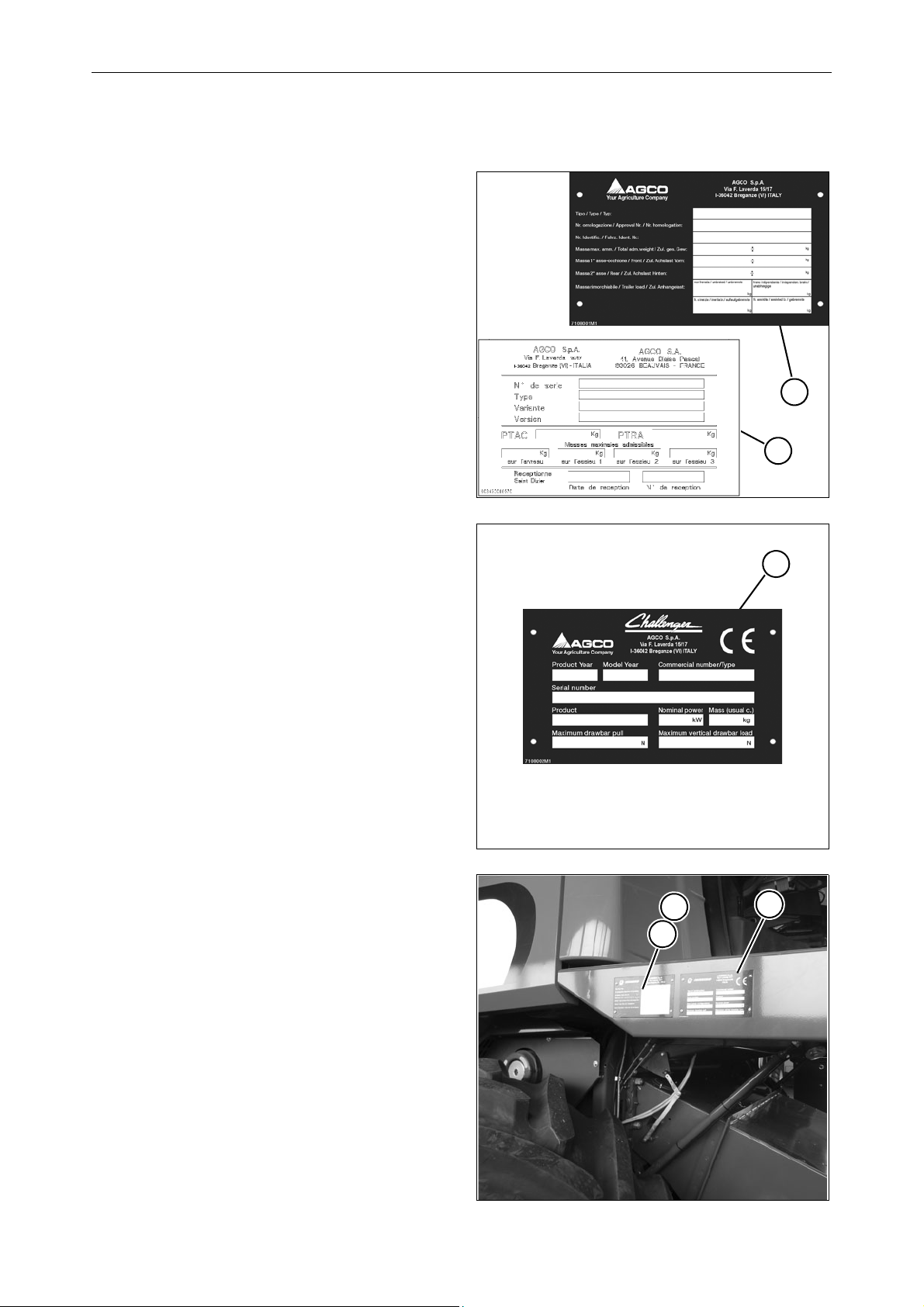
An EC Declaration of Conformity is supplied
with the machine (see facsimile on page 1-8).
• This manual is published for worldwide
distribution, and the availability of equipment
shown as standard or optional varies
according to the territory in which the combine
is to be used. 
Specifications may differ from those contained
in this Operator's Manual according to the
customer's requirements.
• In order to provide a better view of features or
adjustments, certain illustrations in this manual
may show an assembly with standard guards,
or the guards required by law in different
countries, open or removed. However, a
machine should never be operated in this
condition. For your own safety, always
ensure all safety guards are closed and
correctly fitted before operating the
machine.
• This Operator's Manual, along with the the
PTO shaft, must always be kept in the empty
compartment under the passenger seat for
storage and convenient reference.
Company policy
In accordance with the Company's policy of
continuous improvements to its products, the
Company reserves the right to modify and improve
its products whenever necessary and to the
required extent, without any obligation to apply
such modifications to previously sold products. The
information contained in this Manual refers to the
current situation at the time it was written. All the
data given may vary.
Find manuals at http://best-manuals.com/search?&s=CHAl-LA327318013.PDF
GENERAL INFORMATION
1-2 Operator's Manual Combines CHALLENGER 648 C-652 C- EN - LA327318013 - 10/2013
OPTIONAL EQUIPMENT
Your machine was designed to operate in a wide
variety of crops and conditions. However, in certain
cases it may be necessary to fit additional
accessories to improve machine performance or
adapt the machine to harvesting special crops. A
list of available accessories is provided in the
section "Optional Equipment".
SPARE PARTS AND ACCESSORIES
The genuine spare parts and accessories have
been specifically designed for this type of machine.
Only genuine parts supplied by your authorised
Dealer can guarantee correct operation and
optimum performance.
Never use non-genuine spare parts or accessories:
Some accessories (e.g. PTO shafts, straw
choppers, tables) require an EC certification, which
can be provided only by the manufacturer or his
qualified and recognised sub-suppliers.
Non-genuine spare parts have not been tested and
are not authorised by the manufacturer. The fitting
and/or use of such equipment may have a
damaging effect on the design features of the
machine and jeopardise operational safety.
The manufacturer disclaims all liability in the
event of loss or damage arising as a result of
non-genuine parts, accessories or equipment
being used.
It is expressly prohibited to make any modification
to the combine without the prior written
authorisation by the manufacturer.
When ordering spare parts and/or optional
equipment, always quote combine model and serial
number (see section “Combine Identification”).
WARRANTY
Your combine is warranted in compliance with the
regulations in force in your country and the
agreements made with your Dealer.
However, the warranty becomes void in the
following situations:
a.) If the machine has been used inappropriately.
b.) If adjustments and maintenance have not been
carried out according to the instructions in this
manual.
c.) If the failures are caused by the use of
non-genuine spare parts or accessories.
d.) If damage is the result of carelessness,
negligence, inappropriate use of the machine
or operational errors.
If the safety devices are removed and/or
non-genuine spare parts are used, the
warranty becomes void automatically and the
manufacturer disclaims any liability.
The warranty applies only to repair or free
replacement of parts proving defective after a
careful inspection by the manufacturer (excluding
wear parts and tyres), as described in the Combine
Service Record Book. In the event that warranted
parts are replaced or repaired, warranty terms are
not extended. The customer can assert his
warranty rights only insofar as the warranty
conditions contained in the Service Record Book
have been observed.
LUBRICANTS
Your Dealer can provide a wide range of special
lubricants, produced according to the specific
technical specifications of the combine.
For these combines we recommend the use of the
lubricants listed on page 5-42 and on page 5-43.
Only use genuine AGCO parts.
Find manuals at http://best-manuals.com/search?&s=CHAl-LA327318013.PDF
GENERAL INFORMATION
Operator's Manual Combines CHALLENGER 648 C-652 C- EN - LA327318013 - 10/2013 1-3
1.2 APPROPRIATE USE
C series combines are designed as self-propelled units with a diesel engine.
The machines are manufactured exclusively for usual agricultural purposes, i.e. for harvesting cereal, seed,
rice, maize, soya, etc. by cutting or picking-up the crop, threshing and separating the grains from the ears,
delivering the grains in the grain tank and unloading them into the grain wagon.
Machine performance may be limited by various factors such as harvesting speed, weather conditions,
ground characteristics and the type and degree of ripeness of the crop.
When operating the machine, make sure the cab doors are shut. The operator and instructor, if present, must
remain seated in their respective seats with their seatbelts fastened (the operator should not drive the
machine when standing).
The machines may be operated only by skilled personnel, who are thoroughly familiar with all the machine's
functions and harvesting techniques.
Machine stability is ensured on the following inclinations, on condition that the ground is firm and the tyres
offer sufficient grip:
• 30% (18 °) longitudinally (uphill and downhill).
•30%(18°)crosswise.
Forbidden uses
Do not use the machine for tasks or purposes other than those specified in this Manual, on the safety decals
or on other safety information provided with the machine. The following pages contain recommendations on
correct and incorrect use of the machine when travelling on public roads, during field operations and
maintenance.
Many machine functions related to safety are managed by the software.
Do not try to modify or replace the software. You risk damaging the settings and the operating logic of the
machine.
Such tampering could lead to unpredictable and abnormal behaviour, making it unsafe for the operator(s)
and the machine.
Only your Dealer is authorised to intervene on the machine software.
The machine's maximum speed on the road is limited and controlled by the software. Do not try to change it.
648 D and 652 D models
The above combine models are designed for working on level ground to ensure even distribution of the crop
inside the machine. These models HAVE NOT been developed for working on sloping ground.
TABLE TYPES (please see the specific Operator's Manual)
The above-mentioned combines may use 4.80, 5.40, 6.00, 7.00 or 7.60 m cutting tables.
NOTE: In this manual, the term “table/s” signifies both the cutting table and the maize header when used
generically. The term “cutting table” refers to the assembly consisting of reel, cutting bar, table auger, etc.
used to harvest cereal, rice, soya, etc. The term “maize header” refers to the equipment formed by stalk
grippers, stripping blades, conveyor chains, etc. used for maize harvesting.
Find manuals at http://best-manuals.com/search?&s=CHAl-LA327318013.PDF
GENERAL INFORMATION
1-4 Operator's Manual Combines CHALLENGER 648 C-652 C- EN - LA327318013 - 10/2013
1.3 COMBINE IDENTIFICATION
The combine and its main components are
identified by serial numbers and/or production
codes.
The position of the different identification data is
described below.
NOTE: Always quote the combine serial number
when contacting your Dealer for spare parts or
assistance.
Combine approval and safety plates
Fig. 1 – Fig. 3
The manufacturer's type plate, statutory for all
countries (1), or (2) for France only, is positioned on
the outer right-hand side of the operator platform
and shows the following information:
• Combine type.
• Approval number.
• Combine serial number.
• Total maximum permitted weight.
• Weight (on both axles).
• Towing weight.
For further details, please refer to the type approval
certificate.
The safety plate (3) is located next to the approval
plate, and guarantees that the combine was built in
compliance with Machinery Directive 2006/42/EC
as well as Directive 2004/108/EC.
This plate shows the following information:
• Manufacturing year.
• Year of use.
•Model.
• Combine serial number.
• Crop type.
•Totalweight(normal configuration).
• Nominal engine power.
• Maximum towing weight.
• Maximum vertical load on the trailer hitch.
In certain countries (e.g. Russia) these two plates
are positioned next to an additional decal/plate
corresponding to the approval for that specific
country.
Fig. 1
Fig. 2
Fig. 3
1
2
3
1
23
Find manuals at http://best-manuals.com/search?&s=CHAl-LA327318013.PDF
GENERAL INFORMATION
Operator's Manual Combines CHALLENGER 648 C-652 C- EN - LA327318013 - 10/2013 1-5
Combine identification
Fig. 4
Combine type and serial number appear on the
plate and are also punched into the rear right-hand
side of the frame (1).











Engine Identification
Fig. 5
The engine is identified by the type plate (1) in the
middle of the cylinder block.
The following information appears on the plate (1):
• Engine manufacturer
•Enginetype
• Engine power and rated speed
• Engine serial number
• Valve clearance
• Customer reference code
• Idling speed
• Compliance with Directive 97/68/EC
• Name of the engine assembler.
The engine serial number is always also stamped
on the cylinder block.
Cutting table identification
Fig. 6
The cutting table can be identified by a metal plate
affixed on the left-hand side.
Fig. 4
Fig. 5
1
1
Fig. 6
Find manuals at http://best-manuals.com/search?&s=CHAl-LA327318013.PDF
GENERAL INFORMATION
1-6 Operator's Manual Combines CHALLENGER 648 C-652 C- EN - LA327318013 - 10/2013
Operator seat identification
Fig. 7
The identification plate is located on the seat
support and can be reached by moving the seat
fully forwards.
Hydrostatic pump identification
Fig. 8
Identification of the hydrostatic pump is facilitated
by means of a plate located on the pump body front
part.
Hydrostatic motor identification
Fig. 9
Identification of the hydrostatic motor is facilitated
by means of a plate located on the motor body
lower part.
Fig. 7
Fig. 8
Fig. 9
Find manuals at http://best-manuals.com/search?&s=CHAl-LA327318013.PDF