Dion F63 User manual
Instructions d’installation / Installation instructions : F6313T955
Ensemble Adaptateur F63 / Adapter Kit F63: K27760 for ClaasTM harvesters
14 avril 2014 1
Instructions d’Assemblage
Étape 1: Réception
Voir le manuel d’opérateur pour la réception du cueilleur à maïs et l’enlèvement de la
palette de transport. Il est important de retirer la patte de levage temporaire avant le
démarrage.
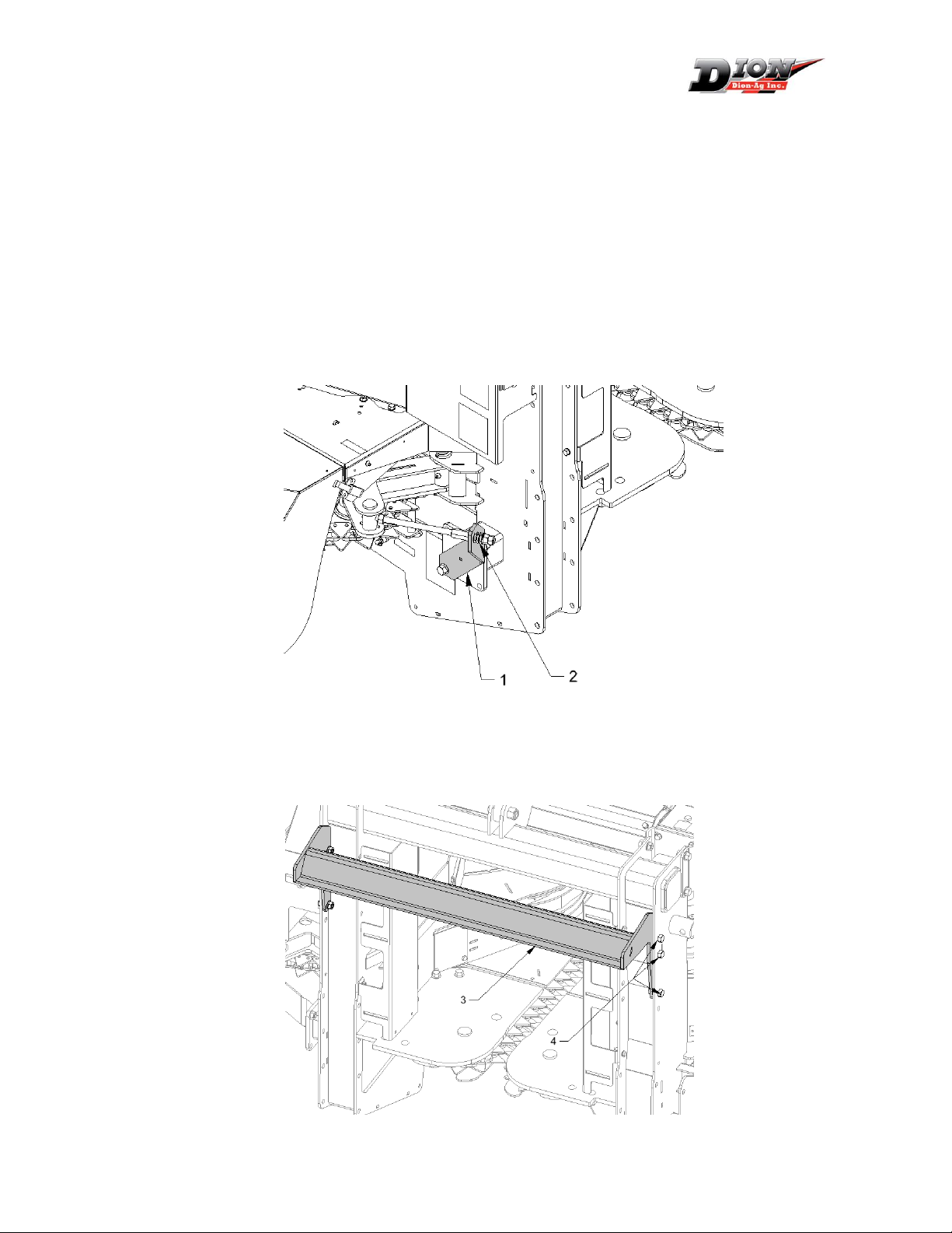
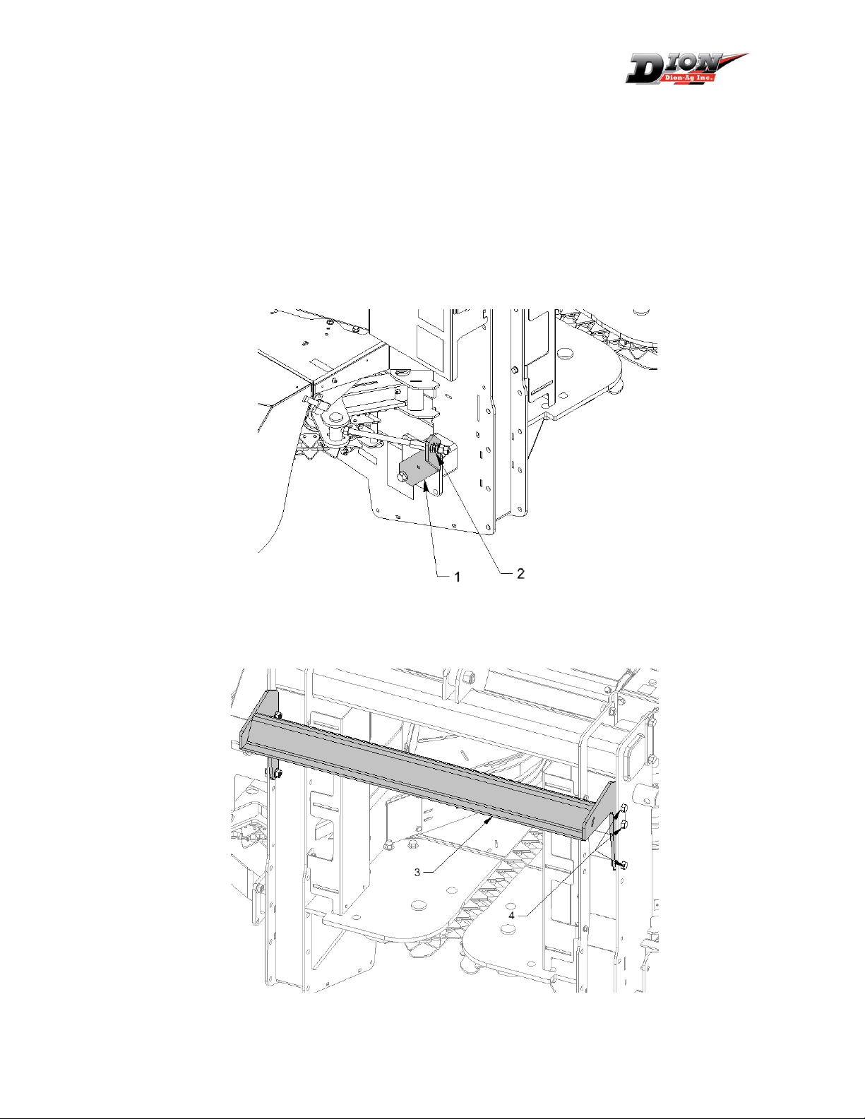
Étape 2 : Préparation
Retirez le support de tendeur (1) et désassembler le ressort (2) de la tige du tendeur en
enlevant les deux écrous ou la goupille fendue (modèle 2013+).
Étape 3 : Installation du lien supérieur
Installez le support supérieur (3) dans les trous indiqués avec 6 boulons à bride ½’’ x 1’’
(4).

Instructions d’installation / Installation instructions : F6313T955
Ensemble Adaptateur F63 / Adapter Kit F63: K27760 for ClaasTM harvesters
14 avril 2014 2
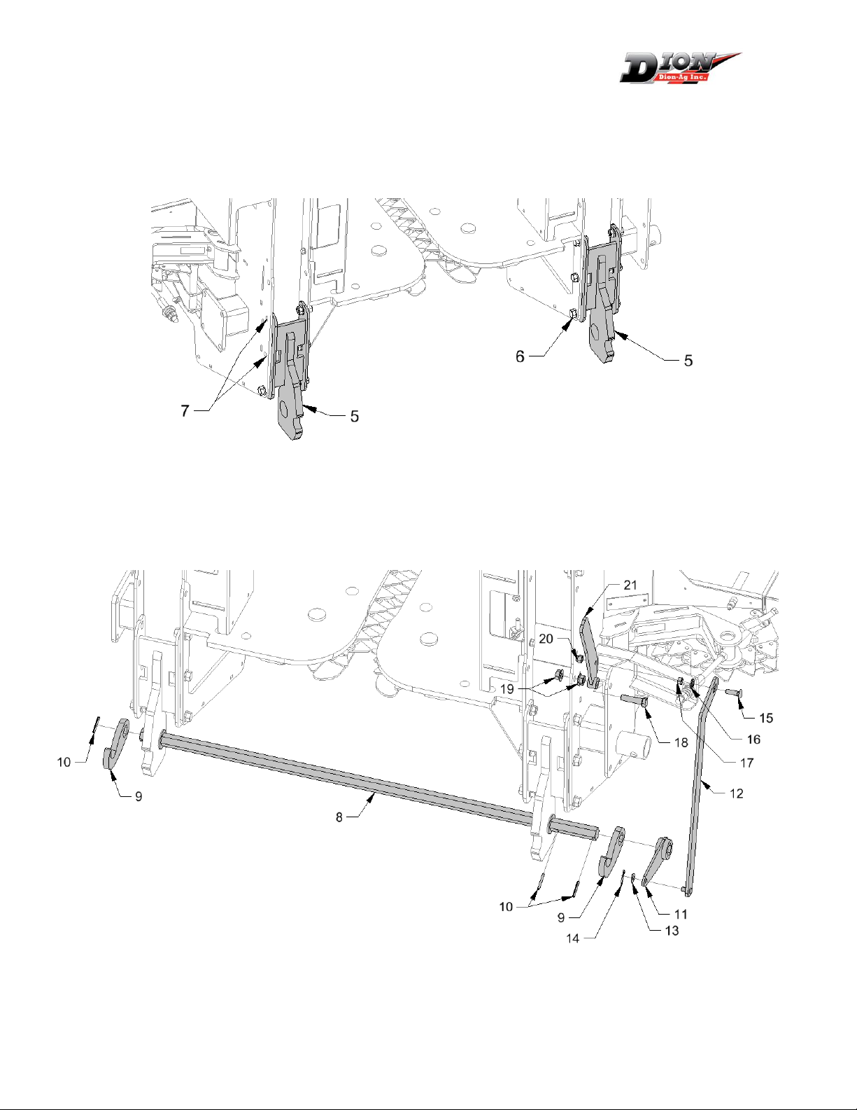
Étape 4 : Installation du module inférieur
Installez les deux modules inférieurs à la position la plus basse à l’aide de boulons à
bride 1/2" x 1". Ne pas installer de boulons à la position (7). Ne pas serrer les boulons
immédiatement.
Glissez l’arbre hexagonal (8) et les crochets (9) et le levier court (11). Barrez en place
avec les goupilles à ressort (10).
Installez la poignée (21) en serrant le boulon 1/2" x 2" (18) avec les deux écrous (19).
Laissez assez de jeu pour que la poignée pivote aisément.

Instructions d’installation / Installation instructions : F6313T955
Ensemble Adaptateur F63 / Adapter Kit F63: K27760 for ClaasTM harvesters
14 avril 2014 3
Serrez le boulon à voiture 3/8" x 1-1/4" (15) sur le
grand levier (12) à l’aide d’une rondelle d’arrêt (16)
et l’écrou hexagonal (17). Utilisez une position
dans le centre de la fente d’ajustement pour
l’instant.
Installez le grand levier (12) au petit (11) avec la
rondelle plate 3/8" (13) et la goupille fendue (14).
Reliez à la poignée (21) à l’aide de l’écrou plastique
(20). Ajustez sans serrer pour laisser le levier
pivoter aisément.
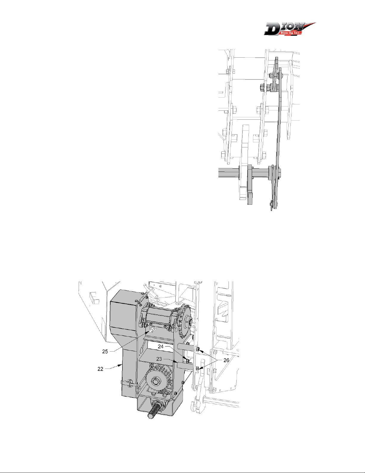
Étape 5 : Installation du module d’entraînement
À l’aide d’un palan, soulevez le module d’entraînement (22) et installez sur le châssis à
l’aide de 4 boulons 1/2" x 1-1/2" (24).
Insérez les espaceurs (23) et installez les boulons 1/2" x 5" (26).
Réinstallez la tige du tendeur de chaîne (25) en suivant les instructions dans le manuel
d’opérateur. Il est important de régler la tension selon les instructions du manuel pour
éviter l’usure prématurée de la chaîne.
Instructions d’installation / Installation instructions : F6313T955
Ensemble Adaptateur F63 / Adapter Kit F63: K27760 for ClaasTM harvesters
14 avril 2014 4
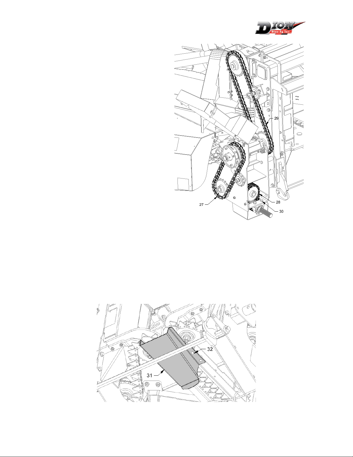
Étape 6 : Installation des chaînes
d’entraînement
Installez les trois chaînes
d’entraînement tel qu’indiqué.
Ajustez les tendeurs pour obtenir un
jeu total d’environ 1/4" sur le côté
mou.
En cas de besoin, l’arbre d’entrée
peut être déplacé pour tendre la
chaîne triple (28) en desserrant les 4
boulons des roulements (30).
Étape 7 : Installation optionnelle
Fournir au client le dalot (31) SANS L’INSTALLER. Le dalot est utilisé seulement pour les
conditions de récolte sèche pour réduire les pertes d’épis possible. Il sert à éviter les
pertes entre le nez et les rouleaux d’alimentation de la fourragère. Il doit être retiré
dans les conditions normales pour éviter les bourrages. Pour l’installer, utiliser les
boulons qui retiennent les guides de sortie sous la chaîne (32). Laisser les guides en
place lorsque le dalot est installé.
Instructions d’installation / Installation instructions : F6313T955
Ensemble Adaptateur F63 / Adapter Kit F63: K27760 for ClaasTM harvesters
14 avril 2014 5
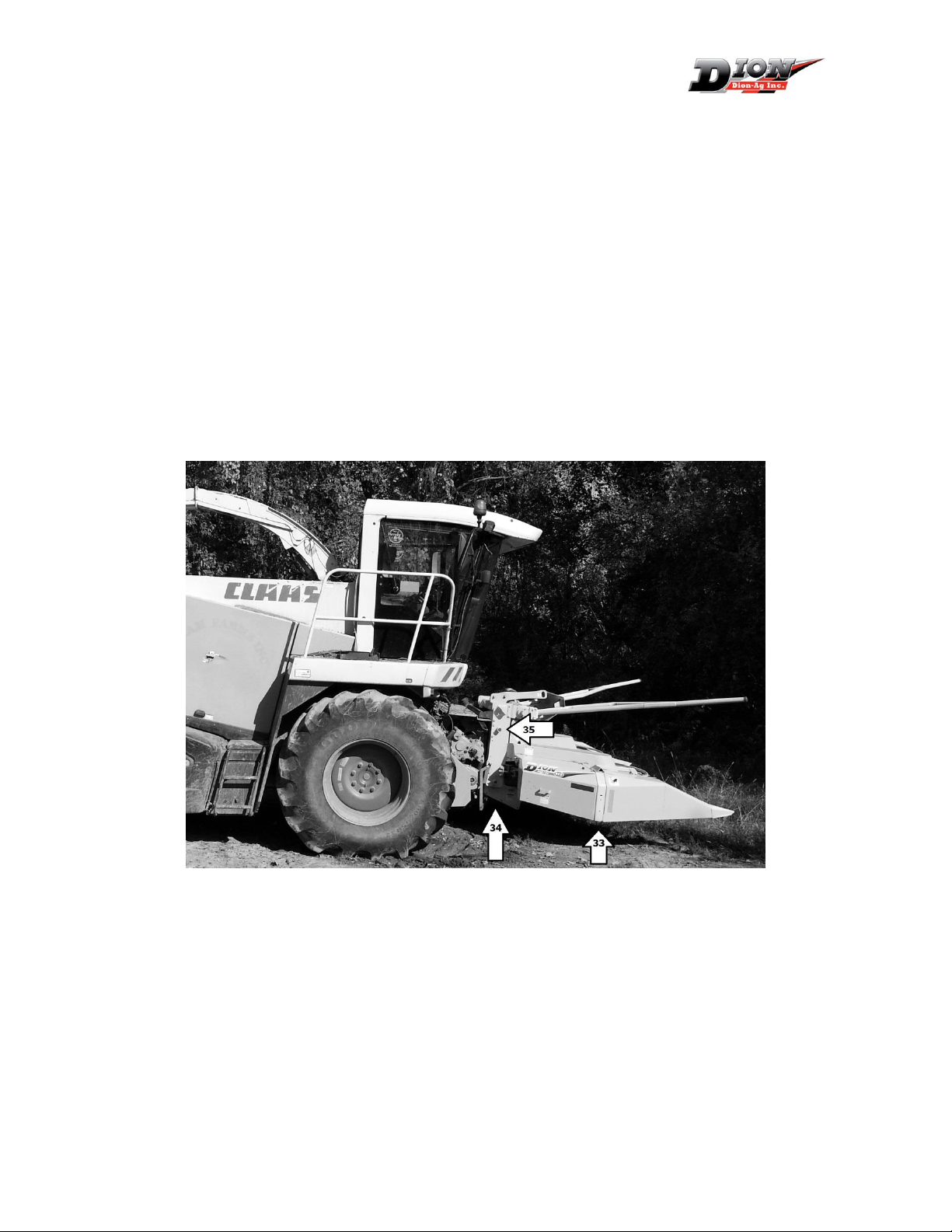
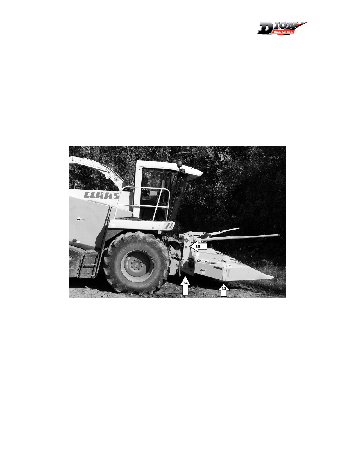
Étape 8 : Installation sur la fourragère
Pour faciliter l’installation du nez sur la fourragère, soulever le nez par le crochet de
relevage et déposer des blocs d’environ 4’’ à 6’’ (10 à 15cm) d’épais sous les patins (33).
Les blocs fournissent un meilleur angle d’inclinaison pour l’accrochage.
Soulever l’arrière du nez à l’aide du vérin (34) inclus en le plaçant en position
entreposage (35).
Soulever le nez avec la fourragère verrouillez les crochets de sureté.
Vérifiez l’emboîtement des crochets du bas et ajustez la position des supports inférieurs
au besoin
Ajustez l’ajustement du levier de barrure (21).
Installez l’arbre de transmission fourni pour l’entraînement et fermer le garde de
protection sur la fourragère.
Étape 12 : Opération
Se référer au manuel d’opérateur pour la mise en marche et les ajustements nécessaires
dans les premières heures d’opération.
Ajuster la suspension tel que recommandé par les instructions du manufacturier de la
fourragère.
Suivre un programme d’entretien rigoureux pour assurer une durabilité de la machine.
Instructions d’installation / Installation instructions : F6313T955
Ensemble Adaptateur F63 / Adapter Kit F63: K27760 for ClaasTM harvesters
14 avril 2014 6
Installation Instructions
Step 1: Reception
See the operator’s manual for instructions on receiving and removing the skid from the
header. Remove the temporary lifting arm before operating the header.
Step 2: Preparation
Remove the tightener temporary support (1) and disassemble the spring (2).
Step 3: Top link Installation
Install the top link (3) in shown position with 6 flange bolts ½’’ x 1’’ (4).
Instructions d’installation / Installation instructions : F6313T955
Ensemble Adaptateur F63 / Adapter Kit F63: K27760 for ClaasTM harvesters
14 avril 2014 7
Step 4: Installation of the lower links
Install the two lower links in the lowest position on the header frame using 1/2" x 1"
flange bolts. Do not install bolts in position (7), Do not tighten immediately.
Slide the hexagonal shaft (8), the cook (9) & short lever (11). Lock in place with the
spring pins (10).
Install the lock handle (21) by tightening the 1/2" x 2" hexagonal bolt (18) with two
flange nuts (19). Leave enough play to allow the handle to rotate smoothly.
Instructions d’installation / Installation instructions : F6313T955
Ensemble Adaptateur F63 / Adapter Kit F63: K27760 for ClaasTM harvesters
14 avril 2014 8
Tighten the carriage bolt 3/8" x 1-1/4" (15) on the
long lever arm (12) with a lock washer (16) and the
hexagonal nut (17). Use a centre position in the
adjustment slot for now.
Fit the long lever (12) to the short one (1) using a
3/8" flat washer (13) and the cotter pin (14).
Fasten to the handle (21) using a plastic lock nut
(20). Adjust to allow the handle to pivot freely.
Step5: Drive module Installation
Using a winch, lift the drive module (22) and install on the frame using four 1/2" x 1-1/2" bolts
24).
Insert the spacers (23) and fasten with 1/2" x 5" bolts (26).
Reinstall the header chain binder (25) following the instructions in the operator’s
manual. Setting proper chain tension is critical to prevent excessive or premature
chain wear.

Instructions d’installation / Installation instructions : F6313T955
Ensemble Adaptateur F63 / Adapter Kit F63: K27760 for ClaasTM harvesters
14 avril 2014 9
Step 6: Drive chain installation
Install the three drive chains as shown.
Adjust the two binders to obtain a
total play of 1/4" on the slack side.
If required, the input shaft can be slid
sidways to tighten the triple chain
(28) by loosening the 4 bearing bolts
(30).
Step 7: Optional Installation
Give the crop channel (31) to the client/operator WITHOUT INSTALLING IT. The
channel is used only for dry conditions to reduce ear losses. It prevents losses between
the header and the feedrolls in these tough conditions. It must be removed to operate
in normal conditions to avoid the risk of plugging. To install, use the bolts holding the
two guides below the rear idler sprockets (32). Lthe guides in place even when the
channel is installed.
Instructions d’installation / Installation instructions : F6313T955
Ensemble Adaptateur F63 / Adapter Kit F63: K27760 for ClaasTM harvesters
14 avril 2014 10
Step 8: Installation on the harvester
To facilitate the header pick-up, set the header on 4’’ à 6’’ (10 - 15cm) thick blocks under
the front shoes (33). The blocks will give a better inclination angle for direct pickup with
the harvester.
Set the rear of the header on the provided lift jack in the storage position (34).
Pick up the header and lock the safety hooks. Remove the lift jack and set in transport
position (35).
Drop the head and readjust the lower links (5) position if the hook points are not
aligning properly. Same with the lock handle (21)
Install the drive shaft provided and close all guards before operating.
Step 12: Operation
Refer to the operator’s manual for the start-up and run-in procedure.
Adjust the harvester suspension as recommended by the harvester manufacturer.
Follow a strict maintenance program to ensure the machine durability.
Refer to the operator’s manual for storage and end of season procedure.
This manual suits for next models
1
Table of contents
Languages:
Other Dion Farm Equipment manuals


Popular Farm Equipment manuals by other brands


Grammer
Grammer MAXIMO Evolution Dynamic operating instructions

HAYGAIN
HAYGAIN HG ONE user manual

GREAT PLAINS
GREAT PLAINS 3N-4010F Series Operator's manual

Fratelli Camisa
Fratelli Camisa TP 280 ECO Instruction manual for use and maintenance

AGI
AGI Westeel EasyFlow2 100 Series Assembly & installation manual

Amazone
Amazone Ceus 3000-TX Original operating manual