Chalmit 503 Owner's manual
I-503I-01.doc Issue 10 14th July 2016 1
IOM –503 - HIGH WATTAGE FLOODLIGHT (IND)
Issue
10
INSTALLATION, OPERATION AND MAINTENANCE INSTRUCTIONS
503 - High Wattage Floodlight Luminaires
Industrial
Important:
Please read these instructions carefully before installing or maintaining this equipment.
Good electrical practices should be followed at all times and this data should be used
as a guide only.
600W SON/T Version

I-503I-01.doc Issue 10 14th July 2016 2
IOM –503 - HIGH WATTAGE FLOODLIGHT (IND)

I-503I-01.doc Issue 10 14th July 2016 3
IOM –503 - HIGH WATTAGE FLOODLIGHT (IND)
0.0 Specification
Type Of Protection
N/A
Standards
EN 60598-1
Area Classification
Non- Hazardous
Ambient
see table 1
Ingress Protection
IP66/67 to EN 60529
CE Mark
The CE marking of this product applies to "The Electrical Equipment (Safety) Regulations
2006", "The Electromagnetic Compatibility Regulations 2004", the “Waste Electrical and
Electronic Equipment Regulations 2006”. [This legislation is the equivalent in UK law of EU
directives 2014/35/EU, 2014/30/EU, 2012/19/EU respectively].
M Poutney Technical Manager
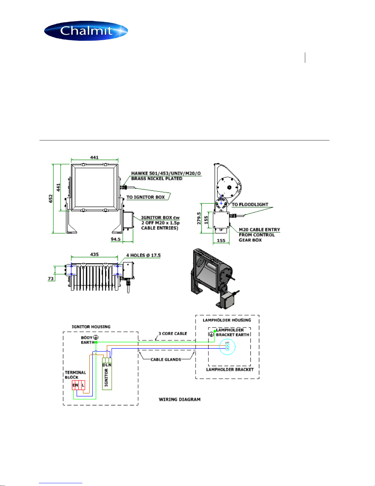
1.0 Introduction - 503 High Wattage Floodlight
The 503 series of Industrial floodlights are designed for area lighting applications. The maximum ambient
temperature is as shown. The unit is used in conjunction with a control gear box.
Note: Lamp ranges and ambient temperature ratings are as indicated in TABLE 0.
2.0 Storage
Luminaires and control gear boxes are to be stored in cool dry conditions preventing ingress of moisture and
condensation.
Any specific instructions concerning emergency luminaires must be complied with.
3.0 Installation and Safety
3.1 General
There are no health hazards associated with this product whilst in normal use. However, care should be
exercised during the following operations. Installation should be carried out in accordance with good electrical
procedure and local code of practices.
In the UK the requirements of the 'Health and Safety at Work Act' must be met.
Handling and electrical work associated with this product to be in accordance with the ‘Manual Handling
Operations Regulations' and 'Electricity at Work Regulations, 1989'. Your attention is drawn to the paragraphs (i)
'Electrical Supplies', (ii) 'Electrical Fault Finding and Replacement' and (iii) 'Inspection and Maintenance'. The
luminaires are Class 1 and should be effectively earthed.
The luminaires are quite heavy and suitable means of handling on installation must be provided.
The information in this leaflet is correct at the time of publication. The company reserves the right to make
specification changes as required.
3.2 Special conditions for Installation.
Special conditions for safe use
1 The method of cable entry shall be such as to retain the ingress protection properties of the luminaire. In
particular, if conduit entry is used, a stopper gland shall be inserted in the conduit.
2 High pressure sodium lamps shall be used only in conjunction with ballasts which limit the power input to a
lamp to its rated value, when operating at the rated supply voltage. The ignitor circuit shall not produce a
pulse voltage in excess of 4.5kV peak.
Note: Unless authoritative information to the contrary is available from the manufacturer of a
particular lamp, it must be assumed that the use of a lamp with an internal ignitor will infringe
this requirement.

I-503I-01.doc Issue 10 14th July 2016 4
IOM –503 - HIGH WATTAGE FLOODLIGHT (IND)
3.3Tools
3mm and 5mm flat blade screwdriver.
14mm and 15mm A/F spanners.
Suitable spanners for installing cable glands.
Pliers, knife, wire strippers/cutters.
3.4Electrical Supplies
The discharge lamp luminaires are supplied from separate control gear boxes. The installation and operating
instructions for these boxes are dealt with in a separate leaflet.
The supply voltage and frequency should be specified for the control gear box when ordering. Running at over
the rated supply voltage will reduce life and at greater than +10% will compromise the fitting. A maximum voltage
variation of +/-6% on the nominal is expected. (The safety limit for operation is +10%). Luminaires should not be
operated continuously at more than +6%/-10% of the rated supply voltage of the control gear or tapping. The
user must determine the actual underlying site supply and purchase or adjust accordingly. Care is needed in
connecting to the nominal 230V UK public supply.
In some cases, the control gear boxes have multi-tap control gear which can be set to a range of 50 and 60Hz
cycle voltages. The tappings are shown on the control gear and the limits are shown on the rating plate. If, the
equipment is located in a high or low voltage section of the system, an appropriate voltage tap should be selected
to obtain the best lamp performance, but care must be taken to log or mark the equipment so that the tappings
can be reset if the equipment is re-located. If in doubt, tappings should be set on the high side.
In the case of the HPS lamp the ignitor is fitted in a box attached onto the foot mounting bracket, care should be
taken to ensure the lid orientation is correct to align gasket and sealing edge on body. In this case, a control gear
box without an ignitor is ordered to supply the luminaire. A calculation can then be made to cover the voltage
drop between the control gear box and the luminaire. 10V maximum drop is desirable for HPS. The lamp power
will be reduced. In all cases, the calculation is made on the lamp current, not the corrected circuit current.
The HPS circuit uses a SIP (superimposed pulse) ignitor. This means there are only two connections to the
choke and the tap selection is obvious.
When the construction site supply is different to that of the service location, the tappings should be re-set. If not,
advice on the effect of these temporary supplies should be sought from the Technical Department.
3.5Lamps
When fitting lamps, a check should be made that the lamp steady assembly does not become solid before the
access cover has been fully bolted down. There may be some variation in length on the 1000W SON/T lamps
available.
Chalmit recommends Philips 1000W lamps 390mm long. In the later models, the length variation is catered for by
a lamp steady using a spacer. This spacer can be put either on the stem or inside the steady cup to allow for a
2mm shift in the steady spring compression range. The assembly is available for retrofit for older models.
Care must be taken to fit the correct lamp in order that it will operate properly, maintain the operating conditions
and obtain the design photometric performance.
HPS lamps should be replaced shortly after they do not light. One indication of the end of life for HPS
lamps is "cycling", where the lamp goes out and then re-ignites after a minute or so interval. If discharge
luminaires are burnt continuously, they should be switched off occasionally. This allows old lamps to fail to re-
ignite, reducing the possibility of them becoming diodes with detrimental effects to the control gear.
The above information is current at the time of preparation. The development of lamps and control gear is
ongoing and detailed advice on the lamp performance can be obtained from the lamp supplier.
Note: HPS circuits should not be energised without the lamp fitted.
HPS lamps with internal ignitors must not be used.
3.6 Mounting
Luminaires should be installed where access for maintenance is practical and in accordance with any lighting
design information provided for the installation. This will usually consist of aiming points and aiming angles. The
foot mounting brackets should be secured with lock washers or self-locking nuts and bolts.

I-503I-01.doc Issue 10 14th July 2016 5
IOM –503 - HIGH WATTAGE FLOODLIGHT (IND)
3.7Cabling and Cable Glands
3.7.1 Cables
The temperature conditions at the supply cable point are such that 70°C cable can be used in all the luminaires.
The cable between the luminaire and the ignitor/junction box is a high temperature rated cable and is able to
withstand the starting impulse. The Chalmit cable supplied/fitted meets the requirements of the application and
when fitted into the cable glands supplied ensure the IP rating.
3.7.2 Cable Glands
Cable glands and sealing plugs when installed must maintain the ingress protection of the enclosure. Rubber
sealing washers and steel compression washers are provided with the unit. The user must ensure that the
assembly fulfils the above requirement.
Cable entries suitable for M20 cable glands are standard.
3.8 Cabling and Fitting Lamps
Access for lamping is via the end plate at the opposite end to the cable gland.
3.9Inspection and Maintenance
Visual inspection should be carried out at suitable intervals, frequently if conditions are severe. The time
between lamp changes could be very infrequent and this is too long a period without inspection.
3.10 Routine Examination
The equipment must be de-energised before opening. Individual organisations will have their own procedures.
What follows are guidelines based on Chalmit’s own experience:-
1 Ensure that the lamp is lit when energised and that the lampglass is not damaged.
2 When de-energised and left to cool, there should be no significant sign of internal moisture. If there are
signs of water ingress, the luminaire should be opened up, dried out, and any likely ingress points
eliminated by re-gasketting. With the type of construction used in the 503, anything other than slight
condensation should be very rare.
3 Check the cable gland for tightness and nip up if necessary.
4 Check any external earthing connections.
5 Check the access cover and lamp housing screws for tightness and nip up if necessary. Torque 16Nm.
If the covers are removed it is good practice to replace the gasket.
6 Check the silicone sealant used to secure the lampglass. If it has become seriously discoloured or very
soft, the luminaire will need to be returned to Chalmit for re-glazing. The material used for glazing has a
long life and in normal applications would not be expected to deteriorate. Direct contamination with
hydrocarbon oils could cause degradation.
7 Check that the lamp glass retaining clamps are in place and secure. (The purpose of these clamps is to
reduce the load on the lamp glass caused by internal pressure build up from the high temperature of the
light sources).
8 Clean the lamp glass.
9 When re-lamping, the incoming and lampholder terminals should be checked for signs of overheating and
the terminals tightened up.
10 After checking terminals within Ignitor box on leg, care should be taken to ensure the lid orientation is correct
to align gasket and sealing edge on body. To assist alignment an “I” is stamped across the lid and the body.
The lid should be fitted so that the “I” aligns.
3.11 Electrical Fault Finding and Replacement
Similarly, a bad contact at the lamp cap will usually result in discoloration as a sign of overheating. Any fault
finding must be done by a competent electrician and, if carried out with the luminaire in place, under a permit to
work. With HPS the ignitor can become faulty. If the lamp is fitted, the choke has continuity and the connections
are good and correct, they should produce an "attempt to start" flicker effect on the lamp and a buzzing sound
from the ignitor. It will be unusual to have no other parts available to perform a substitution fault finding routine
and this is the normal procedure. Before re-assembling, all connections should be re-checked and any damaged
cable replaced. The supply must be isolated.
I-503I-01.doc Issue 10 14th July 2016 6
IOM –503 - HIGH WATTAGE FLOODLIGHT (IND)
4.0 Overhaul
The unit is largely made of materials, which are very corrosion resistant. Overhaul consists of cleaning and
replacement of gaskets where necessary. All the spares required are available from Chalmit. Please state the
model number and lamp type. No unauthorised modifications should be made.
5.0 Fuse Ratings
The following remarks concern HID lamp circuits at the input side of the control gear box. The output side of the
control gear box carries the lamp current, not the circuit current. The lamp current is shown in Table 1. This
value should be used for any calculations of voltage drop between the control box and luminaire. Where the
ignitor for HPS is contained in the control gear box, the cable also carries the starting pulse. The choke acts as a
current limiter, therefore there is no means of protecting against a line to neutral fault on the electrical circuit
beyond the choke. Extra care must therefore be taken to ensure sound cable installations. The fuse ratings for
HID lamp circuits need to take into account three components of circuit current. Current inrush to PFC
capacitors, which can be up to 25 x the rated capacitor current and last 1-2 millisecs; lamp starting current
including steady capacitor current, which together may decline from up to 200% of normal at 10 seconds after
switch-on to normal after 4 minutes; rectification effects caused by asymmetrical cathode heating for a few
seconds after starting, this effect is random and very variable.
With the availability of MCB's with a wide range of characteristics, the individual engineer can make a better
judgement of what is required. Use MCB's suitable for inrush currents to reduce ratings. The normal capacitor
current will probably be the determining factor, 0.076A per µF at 240V, 50Hz (adjust for other volts by
multiplication, x 6/5 for 60Hz). For HBC fuses use 1.5 x normal capacitor current. All calculations must satisfy
wiring regulations.
Note: Starting and running currents for 240V, 50Hz. are as indicated in TABLE 1.
6.0 Disposal of Material
The unit is mostly made from incombustible materials. The ignitor contains electronic components and synthetic
resins. All electrical components and the body parts may give off noxious fumes if incinerated. Take care to
render these fumes harmless or avoid inhalation. Any local regulations concerning disposal must be complied
with. Any disposal must satisfy the requirements of the WEEE directive [2012/19/EU] and therefore must not be
treated as commercial waste. The unit is mainly made from incombustible materials. The control gear contains
plastic, resin and electronic components. All electrical components may give off noxious fumes if incinerated.
6.1 Lamps
Incandescent lamps and discharge lamps in modest quantities are not "special waste". The outer envelope
should be broken in the container to avoid injury.
This applies to the UK, there may be other regulations on disposal operating in other countries.
Note: Do not incinerate lamps.
To comply with the Waste Electrical and Electronic Equipment directive 2012/19/EU the
apparatus cannot be classified as commercial waste and as such must be disposed of or
recycled in such a manner as to reduce the environmental impact.

I-503I-01.doc Issue 10 14th July 2016 7
IOM –503 - HIGH WATTAGE FLOODLIGHT (IND)
Tables 0/1
Table 0
Lamp Ranges and Ambient Temperature Ratings
Refer to Section :
1.0
Lamp
Ambient Rating
600W SON/T
T amb -30°C to +60ºC
1000W SON/T
T amb -30°C to +40ºC
1000W MBI
T amb -30°C to +40ºC
2000W MBI
T amb -30°C to +40ºC
Table 1
Starting and Running Currents
Refer to Section :
5.0
Lamp
Lamp A
Start A
Run A
Capacitance
µF
600W SON/T
6.06
5.6
3.1
60
1000W SON/T
10.6
6.9
5.0
100
1000W MBI
8.6
6.9
5.0
100
2000W MBI
10.3
15.8
9.9
100
2000W MBI
Cross Phase
9.6
8.9
5.6
30
I-503I-01.doc Issue 10 14th July 2016 8
IOM –503 - HIGH WATTAGE FLOODLIGHT (IND)
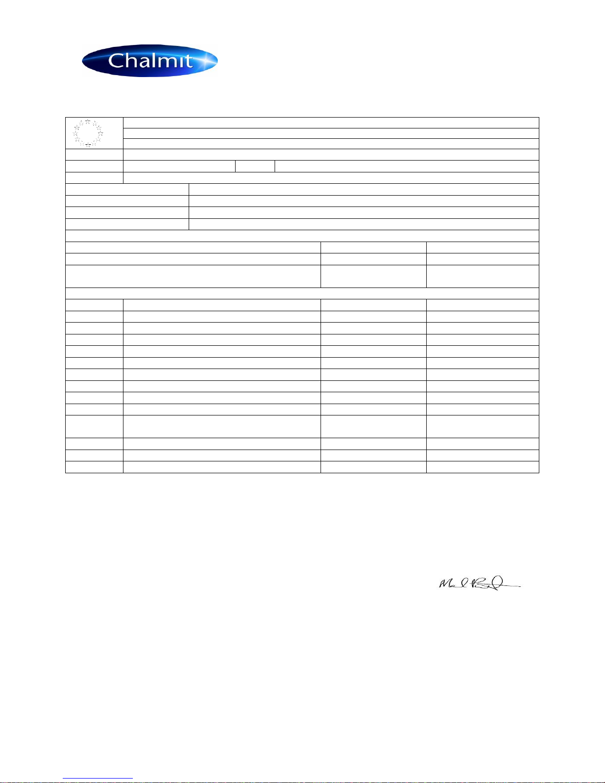
EU-Declaration of conformity
UE-Déclaration de conformité
EU-Konformitätserklärung
Manufacturer
Chalmit
Address
388 Hillington Road, Glasgow. G52 4BL Scotland UK
Product
503 Floodlight Industrial
Catalogue
503I/***/**/** Example: 503I/600/HS/IG
Area Classification
Non- Hazardous
Ingress Protection
IP66/67
Ambient
-30°C to +**°C (see Table 0)
Terms of the directive:
Standard & Date Certified to
Standards Date Declared to
Prescription de la directive:
Standard & date certifiée à
Normes date Déclaré
Bestimmungen der Richtlinie:
Standard & Datum
Zertifiziert nach
Standards Datum erklärt
2014/30/EU
Electromagnetic compatibility
EN 55015 : 2013
2014/30/UE
Compatibilité électromagnétique
EN 61547 : 2009
2014/30/EU
Elektromagnetische Verträglichkeit
EN 61000-3-2 : 2014
2014/35/EU
Low voltage equipment
EN 60598-1 : 2015
2014/35/UE
Équipements électriques à bas voltage
EN 60529 : 1992
2014/35/EU
Niederspannungsgeräte / -systeme
EN 60598-2-5 : 2015
2012/19/EU
Waste of electrical and electronic equipment
2012/19/UE
Déchets d'équipements électriques et électroniques
2012/19/EU
Entsorgung der elektrischen und elektronischen Geräte
/ Systeme
2011/65/EU
RoHS II Directive
On behalf of the Chalmit, I declare that, on the date the equipment accompanied by this declaration is placed on the market, the equipment
conforms to all technical and regulatory requirements of the above listed directives.
En tant que représentant du fabricant Chalmit, je déclare qu'à la date où les équipements accompagnant cette déclaration sont mis sur le
marché, ceux-ci sont conformes à toutes les dispositions réglementaires et techniques des directives énumérées ci-dessus.
Hiermit bestätige ich, im Namen von Chalmit, dass am Tag der Lieferung des Produkts/der Produkte zusammen mit dieser Erklärung das
Gerät/die Geräte alle technischen und regulativen Anforderungen der oben aufgeführten Direktiven erfüllt.
Name and Date
Mark Poutney
14/07/2016
Technical Manager
Nom et Date
Directeur technique
Name und Datum
Technischer Leiter
Quality Management System Acreditation:
ISO 9001
Système de Management Qualité Accréditation:
Qualitätsmanagementsystem Akkreditierung:
Environmental Management System.
ISO 14001
Système de gestion de l'environnement.
by/par/durch
Umwelt kontroll system.
Loyd's Register
Certificate No./Certificat N°/Zertifikat Nr.
LRQ 4005876
Other Chalmit Floodlight manuals


Popular Floodlight manuals by other brands

Century
Century UTY-309540 instruction manual

Robe
Robe ColorWash 1200E AT Service manual

Philips
Philips BVP158 LED24/WW NW CW PSU 20W SWB CN Mounting instructions

Equinox Systems
Equinox Systems Cabaret Colour user manual

Megaray
Megaray MR175mk2 Operator and organizational maintenance manual

Advanced
Advanced Arianna Petrarca installation instructions


Deco
Deco D206-LED installation instructions

Cooper Lighting
Cooper Lighting Quartz Flood IMI-179 installation instructions
Red Arrow
Red Arrow FLSMD50Y-1 installation instructions

RECA
RECA Pocket R600 operating instructions

NORTHCLIFFE
NORTHCLIFFE BOREAS C Installation instruction

Eterna
Eterna FL124B installation instructions