manuals.online logo
Brands
  1. Home
  2. •
  3. Brands
  4. •
  5. Chamberlain
  6. •
  7. Gate Opener
  8. •
  9. Chamberlain Elite RSW12V User manual

Chamberlain Elite RSW12V User manual

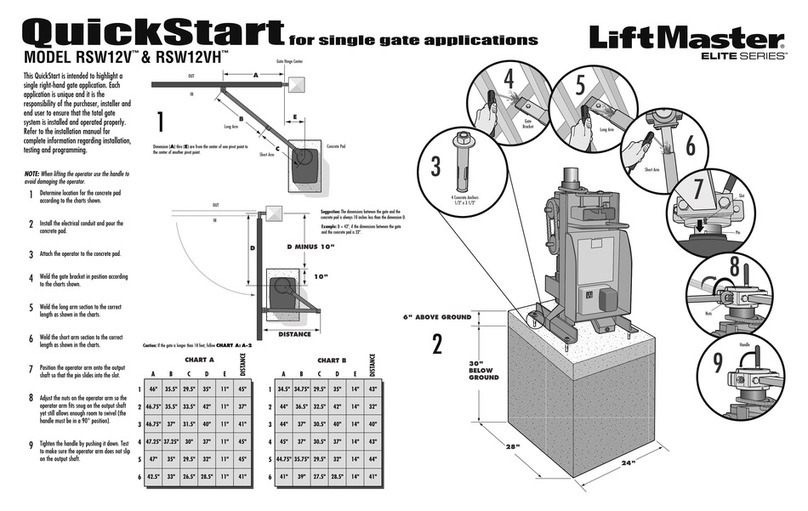
QuickStartforsinglegateapplications
1
2
3
4
5
6
34.5"
44"
44"
45"
44.75"
41"
34.75"
36.5"
37"
37"
35.75"
39"
29.5"
32.5"
30.5"
30.5"
29.5"
27.5"
35"
42"
40"
37"
32"
28.5"
14"
14"
14"
14"
14"
14"
43"
32"
40"
43"
44"
41"
ABCDE
1
2
3
4
5
6
46"
46.75"
46.75"
47.25"
47"
42.5"
35.5"
35.5"
37"
37.25"
35"
33"
29.5"
33.5"
31.5"
30"
29.5"
26.5"
35"
42"
40"
37"
32"
28.5"
11"
11"
11"
11"
11"
11"
45"
37"
41"
45"
45"
41"
ABCDE
DISTANCE
DISTANCE
This QuickStart is intended to highlight a
single right-hand gate application. Each
application is unique and it is the
responsibility of the purchaser, installer and
end user to ensure that the total gate
system is installed and operated properly.
Refer to the installation manual for
complete information regarding installation,
testing and programming.
MODEL RSW12V
™
& RSW12VH
™
Determine location for the concrete pad
according to the charts shown.
Install the electrical conduit and pour the
concrete pad.
Attach the operator to the concrete pad.
Weld the gate bracket in position according
to the charts shown.
Weld the long arm section to the correct
length as shown in the charts.
Weld the short arm section to the correct
length as shown in the charts.
Position the operator arm onto the output
shaft so that the pin slides into the slot.
Adjust the nuts on the operator arm so the
operator arm fits snug on the output shaft
yet still allows enough room to swivel (the
handle must be in a 90° position).
Tighten the handle by pushing it down. Test
to make sure the operator arm does not slip
on the output shaft.
1
2
3
4
5
6
72
4
6
8
9
7
3
8
111
5
9
4 Concrete Anchors
1/2" x 3 1/2"
Gate Hinge Center
A
B
C
E
OUT
IN
Short Arm
Long Arm
Concrete Pad
OUT
IN
DD MINUS 10"
10"
DISTANCE
Dimension (A) thru (E) are from the center of one pivot point to
the center of another pivot point.
Caution: If the gate is longer than 18 feet, follow CHART A: A-2.
Suggestion: The dimensions between the gate and the
concrete pad is always 10 inches less than the dimension D.
Example: D = 42", if the dimensions between the gate
and the concrete pad is 32".
CHART A CHART B
6" ABOVE GROUND
30"
BELOW
GROUND
28"
24"
Gate
Bracket Long Arm
Short Arm
Pin
Slot
Nuts
Handle
CLOSE
EDGE
OPEN EDGE/
PHOTO
OPEN
PHOTO
CLOSE
PHOTO
CONTROL
INPUTS
FORCE TIMER TO
CLOSE
OFF MAX
OPEN
SINGLE BUTTON
RESET
STOP
SHADOW
INTERRUPT
CHGR
OVLD
CTRL PWR
CTRL
LOOP
INPUTS
GATE 2
ACCESSORY
POWER
ALARM
GATE 1
MAGR
SOL
GR
WH
YL
BL
RD
BR
GR
WH
YL
BL
RD
BR
12 V
GATE 2
SET
OPEN
LIMIT
SET
CLOSE
LIMIT
LEARN
LIMITS
GATE 1
LEARN
XMITTER
LOCK /
ON OFF
PWR
OFF MAX
SINGLE BUTTON
AC PWR
/SOLAR
BIPA RT DELAY
LOCK
GND
CTRL PWR
OFF
ON
AUTO OPEN
LOW BATT
Press and release the LEARN XMITTER button (LED will light).
Press the remote control button. The LED will flash and the alarm
output will activate twice.
A
E
G
D
WIRING
FORCE ADJUSTMENT
PROGRAMMING
LEARN LIMITS
Use the SINGLE BUTTON to open and close the gate.
If the gate stops or reverses before reaching the fully open or
closed position increase the force by turning the force control
slightly.
Run operator through a complete cycle.
1
1
3
2
After any adjustments are made, test the operator:
Use the SINGLE BUTTON to open and close the gate.
Test the limits by making sure the gate is stopping at the OPEN
and CLOSE limits.
Test the force by making sure the gate will stop and reverse on
contact with an obstruction.
F
TEST
1
3
2
2
©2010 The Chamberlain Group, Inc.
01-35315B All Rights Reserved
To protect against fire and electrocution:
• DISCONNECT power and battery BEFORE installing or servicing
operator.
For continued protection against fire:
• Replace ONLY with fuse of same type and rating.
BPOWER WIRING OPTIONS
This operator is capable of being powered by the
internal receptacle, an external receptacle or a solar
panel (not provided).
INTERNAL RECEPTACLE
Remove the access panel.
Connect AC power to the operator:
• Connect the green wire to the ground screw in the
access panel.
• Connect the black and white wires together with
wire nuts.
Replace the access panel.
Connect the wires from the transformer to the
AC PWR/SOLAR terminal located on the control board.
Plug the transformer into the internal receptacle.
EXTERNAL RECEPTACLE
Run low voltage wire between the transformer and the
operator.
Connect the wires from the transformer to the
AC PWR/SOLAR terminal located on the control board.
Plug the transformer into the external receptacle.
SOLAR PANEL
Not provided. See Accessories in the Installation Manual.
1
EARTH GROUND ROD
Install the earth ground rod within 3 feet of the operator.
Attach the ground wire to the ground terminal on the
control board.
1
CCONNECT BATTERIES
1
2
Locate the battery plug.
Connect the battery plug to either connector on the control
board.
Use the proper earth ground rod for your local area. The
ground wire must be a single, whole piece of wire. Never splice
two wires for the ground wire. If you should cut the ground
wire too short, break it, or destroy its integrity, replace it with a
single wire length.
REMOTE CONTROLS
2
FORCE
OFF MAX
SINGLE BUTTON
LEARN
XMITTER
SINGLE BUTTON
3
4
5
1
2
3
2
Press and hold the GATE 1 right button to move the gate to the desired
CLOSED position. When the gate is in the desired position, release the button.
NOTE: The GATE 1 right and left buttons can be used to jog the gate back
and forth as needed.
When gate is in the desired CLOSED position, press and release the
LEARN LIMITS button. The control board will beep and the SET CLOSE LIMITS
LED will stop blinking.
Programming is now complete. (If the SET OPEN LIMIT LED continues to blink, repeat programming.) Test the limits by
pressing the SINGLE BUTTON to open and close the gate.
Close the gate. Make sure the operator arm is properly seated on the output shaft (the pin must fit into the slot). Make
sure the handle is released on the operator arm and the learn limit cam is touching the learn limit switch.
PROGRAM OPEN
Manually open the gate to the desired open position.
Tighten the handle on the operator arm.
Press and release the LEARN LIMITS BUTTON. The SET OPEN
LIMIT LED will blink.
Press and release the LEARN LIMITS button again. The control
board will beep and the SET CLOSE LIMITS LED will blink.
SINGLE GATE RIGHT-HAND SIDE
1
2
3
4
5
PROGRAM CLOSE
GATE 2
GATE 1
SET
OPEN
LIMIT T
SET
CLOSE
LIMI
NLEAR
LIMITS
A
B
C
Operator
Black
Black Red
Red
Earth Ground Rod (Optional)
Battery (provided)
INTERNAL RECEPTACLE SOLAR PANEL
(NOT PROVIDED)
EXTERNAL RECEPTACLE
Access Panel
D
E
F
G
Optional second 7AH, 12V battery
(not provided)
NOTE: One 33AH battery (not provided)
can be used in place of the 7AH batteries.
Second Operator
(Optional)
Power Supply
Relay Adapter Module
Maglock
White
Black
Red
COM
NC
NO
Use the Dual Gate Wiring Kit (refer to the
accessory page of the installation manual).
POWER WIRING OPTIONS
abc
120 Vac
6
7
Pin
Slot Handle
Learn Limit Cam
Learn Limit Switch
Learn Limits Button
Gate 1 Right Button
a
b
c

Other manuals for Elite RSW12V

3

This manual suits for next models

1

Other Chamberlain Gate Opener manuals

Chamberlain INSL24UL Guide

Chamberlain

Chamberlain INSL24UL Guide

Chamberlain LiftMaster UGO300M User manual

Chamberlain

Chamberlain LiftMaster UGO300M User manual

Chamberlain LiftMaster Professional SL585GL User manual

Chamberlain

Chamberlain LiftMaster Professional SL585GL User manual

Chamberlain LA400U User manual

Chamberlain

Chamberlain LA400U User manual

Chamberlain 3000 User manual

Chamberlain

Chamberlain 3000 User manual

Chamberlain LiftMaster Professional BG770 Manual

Chamberlain

Chamberlain LiftMaster Professional BG770 Manual

Chamberlain MyQ Smart Garage Hub User manual

Chamberlain

Chamberlain MyQ Smart Garage Hub User manual

Chamberlain Elite CSW200UL User manual

Chamberlain

Chamberlain Elite CSW200UL User manual

Chamberlain Liftmaster LA405-24 User manual

Chamberlain

Chamberlain Liftmaster LA405-24 User manual

Chamberlain LiftMaster LM60 User manual

Chamberlain

Chamberlain LiftMaster LM60 User manual

Chamberlain LiftMaster Professional SLY2500 User manual

Chamberlain

Chamberlain LiftMaster Professional SLY2500 User manual

Chamberlain AS2 eco User manual

Chamberlain

Chamberlain AS2 eco User manual

Chamberlain Motorlift HC300ML-2 User manual

Chamberlain

Chamberlain Motorlift HC300ML-2 User manual

Chamberlain LiftMaster Professional SL595 User manual

Chamberlain

Chamberlain LiftMaster Professional SL595 User manual

Chamberlain LiftMaster Professional SL585 User manual

Chamberlain

Chamberlain LiftMaster Professional SL585 User manual

Chamberlain LiftMaster LM60 User manual

Chamberlain

Chamberlain LiftMaster LM60 User manual

Chamberlain MIRACLE-ONE User manual

Chamberlain

Chamberlain MIRACLE-ONE User manual

Chamberlain LGJ User manual

Chamberlain

Chamberlain LGJ User manual

Chamberlain LOGIC 5.0 User manual

Chamberlain

Chamberlain LOGIC 5.0 User manual

Chamberlain K1D8389-1CC Parts list manual

Chamberlain

Chamberlain K1D8389-1CC Parts list manual

Chamberlain Liftmaster Elite LA500-S User manual

Chamberlain

Chamberlain Liftmaster Elite LA500-S User manual

Chamberlain ELITE Series User manual

Chamberlain

Chamberlain ELITE Series User manual

Chamberlain Elite RSW12V User manual

Chamberlain

Chamberlain Elite RSW12V User manual

Chamberlain ML550EV User manual

Chamberlain

Chamberlain ML550EV User manual

Popular Gate Opener manuals by other brands

BFT ELI-250 Installation and user manual

BFT

BFT ELI-250 Installation and user manual

Stagnoli HERCULES 230V manual

Stagnoli

Stagnoli HERCULES 230V manual

Duke 110 manual

Duke

Duke 110 manual

CAME FA70230CB installation manual

CAME

CAME FA70230CB installation manual

BFT E5 BT A18 Installation and user manual

BFT

BFT E5 BT A18 Installation and user manual

Mighty Mule 350 installation manual

Mighty Mule

Mighty Mule 350 installation manual

Merlin G930 user manual

Merlin

Merlin G930 user manual

GATEXPERT GT800ACL user manual

GATEXPERT

GATEXPERT GT800ACL user manual

TMT Automation BOXER500E user manual

TMT Automation

TMT Automation BOXER500E user manual

SOMFY Ixengo L 230V RTS installation instructions

SOMFY

SOMFY Ixengo L 230V RTS installation instructions

BelFox 47-21-i instruction manual

BelFox

BelFox 47-21-i instruction manual

Essmann EM 230V/970 installation instructions

Essmann

Essmann EM 230V/970 installation instructions

RIB K400 PLUS 12V Operating and installation instructions

RIB

RIB K400 PLUS 12V Operating and installation instructions

Beninca RI.6MLS Operating instructions and spare parts catalogue

Beninca

Beninca RI.6MLS Operating instructions and spare parts catalogue

BFT PHOBOS N Installation and user manual

BFT

BFT PHOBOS N Installation and user manual

CAME A 3000 installation manual

CAME

CAME A 3000 installation manual

CAME AX3024U installation manual

CAME

CAME AX3024U installation manual

Dormakaba ED50 OHC installation instructions

Dormakaba

Dormakaba ED50 OHC installation instructions

manuals.online logo
manuals.online logoBrands
  • About & Mission
  • Contact us
  • Privacy Policy
  • Terms and Conditions

Copyright 2025 Manuals.Online. All Rights Reserved.