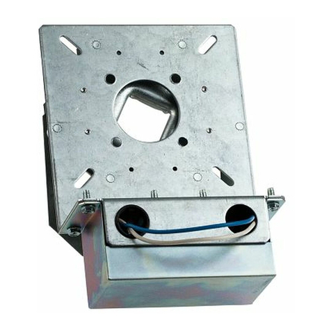
Chamberlain LiftMaster PROFESSIONAL K79-13493-2 User manual

REMOVE AC AND DC POWER
1. Disconnect AC power to the operator.
2. Open operator cover.
3. Remove DC power by disconnecting the battery connection.
REMOVE EXISTING BOARD
1. Match replacement logic board dip switch settings to the
current logic board. Refer to page 7, if needed.
2. Reference page 2 for mechanical assembly details. Remove all
the ends of the wires connected to the existing board and
neatly lay them over the side of the electrical box. Leave
jumper wires located on the board connected until new logic
board wiring.
3. Remove the nylon nuts (7) holding the logic board to the
electrical box and hold for reassembly of new board.
4. Remove the screw holding the heat sink to the electrical box
and hold for reassembly of new board.
5. Remove logic board from the box, leaving the existing
standoffs in place.
INSTALL NEW BOARD
1. Install the new logic board in the electrical box using the old
standoffs. Be sure to install in the same configuration as it was
removed.
2. Secure logic board in place with the nylon nuts (7) removed in
step 3.
3. Secure the heat sink to the electrical box with the screw
removed in step 4.
NOTE: For any additional help, refer to assembly drawing on
page 2.
HOW TO ORDER REPAIR PARTS
OUR LARGE SERVICE ORGANIZATION SPANS AMERICA
Installation and service information
are available 6 days a week
Call our TOLL FREE number:
1-800-528-2806
Monday through Friday 5 a.m. to 6 p.m. (MST)
Saturday 7 a.m. to 7:30 p.m. (MST)
www.liftmaster.com
MODEL K79-13493-2
Logic Board
Replacement Kit
APPLICATION REQUIREMENTS:
Model FDCL operator with charge circuit board incorporating
firmware versions 06-FDCL-500.
FUNCTION:
Replacement of the logic board in an FDCL.
INSTALLATION INSTRUCTIONS
To prevent possible SERIOUS INJURY or DEATH from
electrocution or fire, BEFORE proceeding:
• Disconnect AC power at the fuse box.
• Disconnect DC power at the battery connection.
WARNING
CAUTION WARNING
WARNING
LOGIC BOARD WIRING
1 PHASE OPERATORS
Follow wiring directions on page 3, for additional help refer to the
wiring diagram on page 4.
3 PHASE OPERATORS
Follow wiring directions on page 5, for additional help refer to the
wiring diagram on page 6.
PROGRAM SETTINGS
Follow instructions on page 7 for optional control settings.
CONTROL CONNECTIONS
Follow instructions on page 8 for optional control settings.
1

2
LOGIC BOARD REPLACEMENT ASSEMBLY
Existing Screws
New Logic Board
Existing
Nylon Nuts
Existing Standoff

3
SINGLE PHASE WIRING
NOTE: For additional help with wiring, refer to the wiring diagram
on next page.
EXISTING WIRES
JUMPER WIRES
NOTE: Remove jumpers from original board and install them on
new logic board as follows.
1. Reconnect the original blue wire from pin J18 to pin J12.
2. Reconnect the original yellow wire from pin J23 to pin J22.
3. Reconnect the original black wire from pin J21 to pin J20.
4. Reconnect the original black wire from pin J24 to pin J25.
5. Reconnect the original brown wire that runs from #16 to #23
on the J2 TERMINAL BLOCK.
TRANSFORMER
1. Reconnect the original black wire that runs from the
transformer to pin J20.
2. Reconnect the original white wire that runs from the primary
on the transformer to pin J27.
BRAKE
1. Reconnect the original white wire that runs from the brake to
pin J17.
2. Reconnect the original white wire that runs from the brake to
pin J16.
LOAD RESISTOR
Reconnect the original black wire that runs from the resistor
pin J30.
TERMINAL BLOCK TB1
1. Reconnect the original brown wire that runs from #3 of TB1 to
J9.
2. Reconnect the original brown wire that runs from #4 of TB1 to
J8.
3. Reconnect the original red wire that runs from #2 of TB1
through the inline fuse to J12.
4. Reconnect the original black wire that runs from #1 of TB1 to
the J2 terminal block #15.
5. Reconnect the original black wire that runs from #6 of TB1 to
the J2 terminal block #16.
6. Reconnect the original black wire that runs from #5 of TB1
through the thermal sensor to the J2 terminal block #3.
LIMIT SWITCHES
Reconnect the original limit harness to the 4 pin terminal on the
board marked J3 LIMIT SWITCH.
BATTERY
Reconnect the original black wire that runs from the battery
negative terminal to J14.
MOTOR
NOTE: Steps 1 and 2 affect motor run direction.
1. Reconnect the original grey wire from the motor to pin where it
was removed from either J6 or J7.
2. Reconnect the original purple wire from the motor to pin where
it was removed from either J6 or J7.
3. Reconnect the original yellow wire from the motor to pin J5.
4. Reconnect the original blue wire from the motor to pin J28.
OVERLOAD
1. Reconnect one of the original black wires from the overload to
pin J27.
2. Reconnect one of the original black wires from the overload to
pin J26.
CHARGER BOARD
1. Reconnect the original black wire from the J6 charger terminal
to J15 on the logic board.
2. Reconnect the original white wire from the J1 charger terminal
to #13 on the logic board J2 TERMINAL BLOCK.
3. Reconnect the original white wire from the J2 charger terminal
to #14 on the logic board J2 TERMINAL BLOCK.
4. Reconnect the original blue wire from the J7 charger terminal
to J19 on the logic board.
5. Reconnect the original red wire from the J4 charger terminal to
J13 on the logic board.
NOTE: For pushbuttons, sensing devices, power wiring and other
additional options, refer to the wiring diagram on next page.
INFRARED SENSOR AND BATTERY INDICATORS
1. Reconnect the original white/black wire to J2 terminal block
#1.
2. Reconnect the original white wire to J2 terminal block #2.
3. Reconnect the low battery indicator original white wire to J2
terminal block #15 and the red wire to J2 terminal block #24.
SYSTEM TEST
1. Restore AC and reconnect DC power.
2. Allow the system to stabilize. The alarm may sound for the first
minute. The alarm should remain off after 3 minutes.
3. Verify the OPEN, CLOSE, STOP buttons operate correctly.
4. Verify the safety edge and eyes operate correctly, if
appropriate.
5. Verify the alarm functionality by initiating a Key-Test.

4
SINGLE PHASE WIRING DIAGRAM
INTERNAL 230V - 1PH
MOTOR CONNECTION
(YE)
(GY)
(PU)
3
2
5
8
4
1
(BL)(NOT USED)
(BL)
(BK)
(RD)
(OR)
(WH)
(YE)
J3 J4
J30
J18
J17 J16
J14 J15
J13
J12
J9
J8
J22
J27 J26
J29
J20
J28
J25
J7
J6
J23
J24
J21
J19
J5
S1
123456 7 8 9 10 11 12
181716151413 242322212019
J2 L3
L2L1
J1
DC
BRAKE
COIL
+-
RESISTOR +-
SAFETY
LIMIT SWITCH
CLOSE
LIMIT SWITCH
OPEN
LIMIT SWITCH
+
-
-
+
POWER
DISCONNECT
12 VDC
BATTERY
X2
FACTORY JUMPER (BR)
(K6) OPTIONAL
MOTION STROBE
(K7) OPTIONAL
FIRE SIREN
(K8) OPTIONAL
FIRE STROBE
GND
OUTPUTS
OVERLOAD
IR'S
LOW BATTERY
INDICATOR
REVERSING
EDGE
115 V 1 PHASE
POWER IN ONLY
GND
ALARM INPUT #1
(DRY CONTACT ONLY, DO NOT
INDUCE VOLTAGE)
OPEN
CLOSE
STOP
KEY-TEST
COM NO
SECONDARY
PRIMARY
INTERNAL
THERMAL
SENSOR
ELECTRONIC
FUSELINK
ALARM INPUT #2
(FACTORY JUMPER
SUPPLIED)
(YE)
(RD)
(BL)
(WH)
(BK)
(RD)
(BK) (RD)
(WH) (WH)
(BL)
(YE)
(BK)
(BK)
(YE)
(GY)
(PU)
(BL)
(BK) (BK)
(WH)
(BK)
(BR)
(BR)
(BK)
(BR)
(BR)
(RD)
(BK)
(BK)
(BK)
(RD)
(WH)
(BK)
(RD)
10
9
8
7
6
5
4
3
2
1
SPARE
LIMIT SWITCH
**
(BL) 1
(BK) 5
(RD) 8
(OR) 3
(WH) 2
(YE) 4
INTERNAL 115V - 1PH
MOTOR CONNECTION
SEE NOTE 3
FUSE
2AMP
+24 VDC
24 VAC
24 VAC
GRD
(1 AMP MAX)
(1 AMP MAX)
AUX. POWER
OUTPUTS
J4
(BK)
(WH)
(WH)
(BL)
(RD)
J3J7
J5
(RD)
(RD)
J6
J1
J2
ZILOG PROCESSOR
NOTES:
1. See Owner’s Manual for Dip Switch Functions and Programming Procedures.
2. Connections shown in dotted boundaries are optional user interface.
• (K7, K8) are normally open dry contacts which are programmed to close on
any alarm signal.
• (K6) is a normally open dry contact which is programmed to close when the
door is in motion or inhibited during a gravity close.
3. To reverse motor direction, reverse purple and gray motor wires at J6 and J7
on the logic board.

5
THREE PHASE WIRING
NOTE: For additional help with wiring, refer to the wiring diagram
on next page.
EXISTING WIRES
JUMPER WIRES
NOTE: Remove jumpers from original board and install them on
new logic board as follows.
1. Reconnect the original blue wire from pin J18 to pin J12.
2. Reconnect the original black wire from pin J27 to pin J26.
3. Reconnect the original brown wire that runs from #16 to #23
on the J2 TERMINAL BLOCK.
4. Reconnect the original black wire that runs from J24 to J29.
5. Reconnect the original yellow wire that runs from J21 to J22.
6. Reconnect the original black wire that runs from J20 to J25.
TRANSFORMER
1. Reconnect the original black wire that runs from the primary
on the transformer to J25.
2. Reconnect the original white wire that runs from the primary
on the transformer to J22.
LOAD RESISTOR
Reconnect the original black wire that runs from the resistor pin
J30.
BRAKE
1. Reconnect the original white wire that runs from the brake to
pin J17.
2. Reconnect the original white wire that runs from the brake to
pin J16.
CHARGER BOARD
1. Reconnect the original black wire from the J6 charger terminal
to J15 on the logic board.
2. Reconnect the original white wire from the J1 charger terminal
to #13 on the logic board J2 TERMINAL BLOCK.
3. Reconnect the original white wire from the J2 charger terminal
to #14 on the logic board J2 TERMINAL BLOCK.
4. Reconnect the original blue wire from the J7 charger terminal
to J19 on the logic board.
5. Reconnect the original red wire from the J4 charger terminal to
J13 on the logic board.
INFRARED SENSOR AND BATTERY INDICATORS
1. Reconnect the original white/black wire to J2 terminal block
#1.
2. Reconnect the original white wire to J2 terminal block #2.
3. Reconnect the low battery indicator original white wire to J2
terminal block #15 and the red wire to J2 terminal block #24.
LIMIT SWITCHES
Reconnect the original limit harness to the 4 pin terminal on the
board marked J3 LIMIT SWITCH.
MOTOR
NOTE: Steps 1 and 2 affect motor run direction.
1. Reconnect the original grey wire from the motor to pin where it
was removed from either J6 or J7.
2. Reconnect the original purple wire from the motor to pin where
it was removed from either J6 or J7.
3. Reconnect the original yellow wire from the motor to pin J5.
NOTE: For pushbuttons, sensing devices, power wiring and other
additional options, refer to the wiring diagram on next page.
TERMINAL BLOCK TB1
1. Reconnect the original brown wire that runs from #3 of TB1
to J9.
2. Reconnect the original brown wire that runs from #4 of TB1
to J8.
3. Reconnect the original red wire that runs from #2 of TB1
through the inline fuse to J12.
4. Reconnect the original black wire that runs from #1 of TB1
to the J2 terminal block #15.
5. Reconnect the original black wire that runs from #6 of TB1
to the J2 terminal block #16.
6. Reconnect the original black wire that runs from #5 of TB1
through the thermal sensor to the J2 terminal block #3.
BATTERY
Reconnect the original black wire from the battery through the
power disconnect to pin J14.
SYSTEM TEST
1. Restore AC and reconnect DC power.
2. Allow the system to stabilize. The alarm may sound for the first
minute. The alarm should remain off after 3 minutes.
3. Verify the OPEN, CLOSE, STOP buttons operate correctly.
4. Verify the safety edge and eyes operate correctly, if
appropriate.
5. Verify the alarm functionality by initiating a Key-Test.
6
THREE PHASE WIRING DIAGRAM
INTERNAL 460V - 3 PH
MOTOR CONNECTION
8
9
7
(BR)
(PU)
(YE)
(BR)
(GY)
3
2
14
5
6
INTERNAL 230V - 3 PH
MOTOR CONNECTION
J3 J4
J30
J18
J17 J16
J14 J15
J13
J12
J9
J8
J22
J27 J26
J29
J20
J28
J25
J7
J6
J23
J24
J21
J19
J5
S1
12345678910
11 12
18
17
1615
14
13 24
23
2221
2019
J2 L3
L2L1
J1
DC BRAKE
COIL
+-
RESISTOR +
-
SAFETY
LIMIT SWITCH
CLOSE
LIMIT SWITCH
OPEN
LIMIT SWITCH
+
-
-
+
POWER
DISCONNECT
12 VDC
BATTERY
X2
FACTORY JUMPER (BR)
FUSE
2AMP
(K6) OPTIONAL
MOTION STROBE
(K7) OPTIONAL
FIRE SIREN
(K8) OPTIONAL
FIRE STROBE
GND
OUTPUTS
10
9
8
7
6
5
IR'S
LOW BATTERY
INDICATOR
REVERSING
EDGE
230 / 460 V 3PH
POWER IN
GND
ALARM INPUT #1
(DRY CONTACT ONLY, DO NOT
INDUCE VOLTAGE)
OPEN
CLOSE
STOP
KEY-TEST
COM NO
SECONDARY
PRIMARY
INTERNAL
THERMAL
SENSOR
ELECTRONIC
FUSELINK
ALARM INPUT #2
(FACTORY JUMPER
SUPPLIED)
4
3
2
1
(BK)
(RD)
(YE)
(RD)
(BL)
(WH)
(BK) (RD)
(WH) (WH)
(BL)
(YE)
(BK)
(BK)
(YE)
(GY)
(PU)
(BK)
(BR)
(BR)
(WH) (RD)
(WH)
(BK)
(BR)
(BK)
(BK)(BK)
(BR)
(BR)
(RD)
(BK)
SPARE
LIMIT SWITCH
**
SEE NOTE 3
1
2
3
8
9
7
6
5
4
+24 VDC
24 VAC
24 VAC
GRD
(1 AMP MAX)
(1 AMP MAX)
AUX. POWER
OUTPUTS
J4
(BK)
(WH) (WH)
(BL)
(RD)
J3J7
CCB
J5
(RD)
(RD)
J6
J1
J2
ZILOG PROCESSOR
NOTES:
• Place a jumper between J2-3 and J2-6 when 24 tooth door sprocket is used.
• See Owner’s Manual for Dip Switch Functions and Programming Procedures.
• To reverse motor direction, reverse purple and gray motor wires.
• For B2 wiring, remove one end of jumper from J2-3 and connect to J2-16.

7
OPTIONAL CONTROL SETTINGS
12 3 4
ON (FIRE DOOR MODE TYPE II)
OFF (FIRE DOOR MODE TYPE I)
12 3 4
ON (N.C. ALARM)
OFF (N.O. ALARM)
Terminal
Block (J2)
Terminal
Block (J1)
Heat Sink
DIP Switch (S1)
OPTIONAL CONTROL SETTINGS
NOTE: All functions are independent of each other and do not
require other control settings to be set at any certain
configuration. For dip switch location refer to illustration below.
All switches are factory preset to the “OFF” position.
SI-1 ALARM DELAY TO CLOSE
Alarm Delay to Close is the time between when the
operator first receives an active alarm signal and the door
starts to close (in seconds).
SI-4 INFRARED EYES STATE
The operator will support LiftMaster Infrared Safety Photo
Eyes when enabled, and ignore IR inputs when disabled.
INSTALLER CONTROL SETTINGS
SI-2 MODE
The factory default for the operator is standard Fire Door
Mode Type I (OFF). Setting S1-2 to the (ON) position
selects the Fire Door Mode Type II. When Fire Door Mode
Type I is selected, the control station is in the standard B2
wiring, momentary contact to open, close and stop. When
Fire Door Mode Type II is selected, the control station is in
revised C2 wiring, momentary contact to open and stop,
constant pressure to close with no open override. In
addition, when Fire Door Mode Type II is selected, the
door will Gravity Close (governed descent) on alarm.
SI-3 ALARM STATE
The operator can accept either a normally open or
normally closed dry contact alarm input. DO NOT INDUCE
VOLTAGE!
12 3 4
ON (0 SECOND DELAY)
OFF (10 SECOND DELAY)
12 3 4
ON (IR'S ENABLED)
OFF (IR'S DISABLED)
NOTICE:
This equipment has been tested and found to comply with
the limits for a Class A digital device, pursuant to Part 15 of
the FCC Rules. These limits are designed to provide
reasonable protection against harmful interference when the
equipment is operated in a commercial environment. This
equipment generates, uses, and can radiate radio frequency
energy and, if not installed and used in accordance with the
instruction manual, may cause harmful interference to radio
communications. Operation of this equipment in a
residential area is likely to cause harmful interference, in
which case the user will be required to correct the
interference at his own expense.

CONTROL CONNECTION DIAGRAM
© 2005, The Chamberlain Group, Inc.
01-32777 All Rights Reserved
KEY-TEST
IMPORTANT NOTE:
The 3-Button Control Station provided must be connected for operation.
Keyswitch
9 10 11 12
Stop
Close
Open
6 7 8
SENSING DEVICE TO REVERSE OR STOP
3 BUTTONSTATIONAND SYSTEM TEST
STROBE LIGHT WIRING
ALARM SYSTEM NO OR NC CONTACTS
56
Sensing Device
11 12
NC Contacts
11 12
NO Contacts
J2
J2
J2
J2 J2
Must set DIP switch #3
(S1,3) to ON.
Must set DIP switch #3
(S1,3) to OFF.
15 24
Low Battery
Indicator
15
-+
17
24V Strobe
TB1
218
J2
Installer supplied jumper
IMPORTANT: All inputs must be contact only! This includes: Alarm Inputs, Control Inputs, Sensing Edges and Sensing
Devices. For any other devices not mentioned, please consult the factory.
Table of contents
Other Chamberlain Industrial Equipment manuals

Chamberlain
Chamberlain Commercial Protector System CPS-U User manual

Chamberlain
Chamberlain Clopay HPH1 User manual

Chamberlain
Chamberlain Commercial Protector System CPS-U User manual

Chamberlain
Chamberlain K71-B1PH-1 User manual

Chamberlain
Chamberlain 041-0182-000 User manual

Chamberlain
Chamberlain LiftMaster K72-12564 User manual